[level-membership-for-cardiovascular-category]
Imaging of the Chest
Wilhelm Roentgen discovered the x-ray in 1895 and won the very first Nobel Prize in physics (1901) for this discovery.1 Since that time, radiography has been used in medicine to image the chest structures. Ionizing radiation has its disadvantages, however, as Thomas Edison learned when his laboratory assistant, Clarence Daley, became the first scientist to die of radiation exposure in the United States.1 By the 1940s, ultrasound was being used as a way to image the body using nonionizing radiation.1 Computed tomography (CT) was developed in the 1970s, and magnetic resonance imaging (MRI) in the 1980s.1 All these methods have been used to image the chest, and each offers distinct advantages and disadvantages for the patient and the clinician.
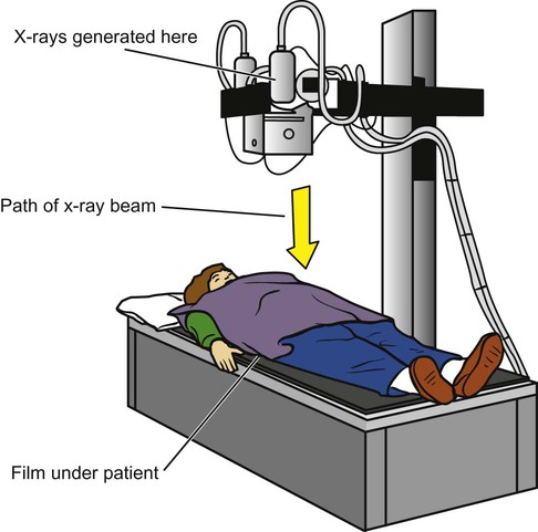
Most imaging machines still use film to capture the image, but newer systems are using digital formats. In either case, the basic methods are similar: x-rays are generated when the anode of an x-ray tube is bombarded with electrons from the cathode of the tube. The collision gives off energy in the form of x-radiation, which travels out of the tube and through the patient, then hitting the imaging cassette. The cassette contains film or a digital imaging sensor. The image is then processed by a digital processor or a film developer (Figure 11-1).
The darkest images on a film (also called radiolucent areas) represent pockets of air within the body. Fat is denser than air, and it produces a dark-gray image. Muscle and other soft tissues are more dense and produce a much lighter gray image. Finally, bone is the most dense natural substance in the body and produces a white image. Metallic objects are even more dense (also called radiopaque) than bone and produce a pure white image (Figure 11-2).
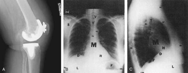
Soft tissues and extrathoracic structures: soft tissues (ST), breast shadows, (BS), diaphragm (D), liver (L), and fundus of stomach (F)
Bony thorax: ribs (RI), vertebrae (V), scapulae (S, seen best on PA), clavicles (C, seen best on PA), and sternum (S, seen best on lateral)
Mediastinal structures: mediastinum (M), trachea (T), carina (CA), aortic knob (AK), heart (H), anterior clear space (ACS, seen best on lateral), and hilus of lungs (HI)
Lung fields: hilus of lungs (HI), pulmonary vessels (arise from hilus and branch outward), costophrenic angles (CPA), and lung apices (LA, seen best on PA) (A from GE Healthcare.)
Figure 11-2, A, demonstrates all the different densities. This lateral view of the knee shows metal from a total knee replacement, along with bone, muscle, fat, and on either side of the patient’s knee, air.2
The x-ray image is a summation of all the densities that the x-rays have passed through. The different layers of tissue that are on top of one another are flattened into a single two-dimensional image. Sometimes the various densities lie next to one another and are easily distinguished in the image. Other times the two densities overlap one another and are blurred together in the image. For this reason, the patient is usually positioned so that two or more images can be taken at a right angle to one another. This allows structures that are overlapping in one orientation to be seen side-by-side with the other orientation.1,3
The Radiograph and Its Evaluation


Evaluation for Pathology
Overview
After verifying the technical aspects of the images, the diagnostic evaluation can begin. It will help to first review the different projections that have been taken (Table 11-1). There are special views that position the patient in such a way that a particular area of interest is oriented for optimal visualization.
Table 11-1
Standard Radiograph Projections
| View | Description |
| AP (anteroposterior) | Frontal view, taken with the patient facing the x-ray tube, with the back toward the film |
| PA (posteroanterior) | Looks the same as the AP, but the patient is positioned facing the film |
| Right lateral | Side view, with the right side against the film |
| Left lateral | Side view, with the left side against the film |
| Oblique | A view taken at a 45-degree angle, between the AP and the lateral views |


At this point it is also important to assess the position of the patient by looking at the clavicles to ensure they are aligned. If they are rotated, this could distort images of the lungs, heart, and other important structures. The image should also be scanned for any nonanatomical findings such as pacemakers, tubes, electrical leads, staples, etc. If old films exist in the patient record, it is helpful to compare the current findings with the old. Once this is done, a more thorough evaluation is begun (Table 11-2).
Table 11-2
Summary of Chest X-Ray Evaluation
| Focus | Findings |
| Patient information | Name, date of birth, social security number, sex, existence of any old films. |
| Nonanatomical findings | Pacemakers, ECG leads, buttons, surgical remnants (e.g., staples), foreign bodies. |
| General inspection | Check rotation of chest by evaluation of the clavicles. Does anything “jump out” at you? Is everything present that should be there? |
| Bones | Are the appropriate number present? Are they in normal anatomical position? Any fractures, lesions? |
| Trachea | Is it midline? Is it narrowed? Are there any foreign bodies? |
| Lungs | Assess inspiratory effort, diaphragms, lung tissue, full expansion of lungs, opacities, infiltrates. |
| Heart | Size, borders, shape. |
| Mediastinum | Is it widened? |
Bony Skeleton
The bony skeleton (Figure 11-3) should be checked for signs of fracture, especially along the margins of the ribs. Fractures are seen as radiolucent lines within the bone or as disruptions of the smooth cortical line at the edges of the bone. Unexplained fragments of bone that are not in a normal anatomical position are another sign of fracture.
Lung Fields
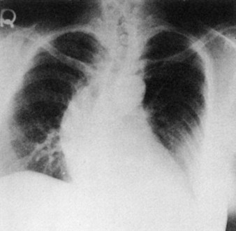
Next, the lung fields should be evaluated for uniform density and vascular markings throughout. The hilar area, where the vascular and airway structures converge, is normally more dense and can be an area of importance when looking for masses or tumors. The peripheral lung fields, where the smallest vascular and airway structures are, appear the smoothest and least dense. Comparing them side by side for symmetry helps in the recognition of abnormal areas. Conditions such as pneumonia, tumor, effusion, or other disease processes lead to consolidation of lung tissue, making it more dense than tissue in the rest of the lung fields (Figure 11-4).
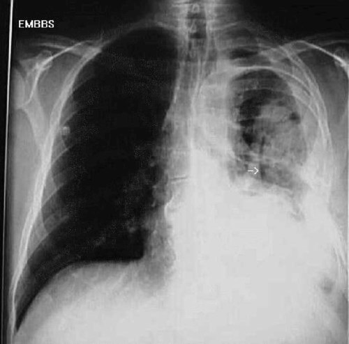
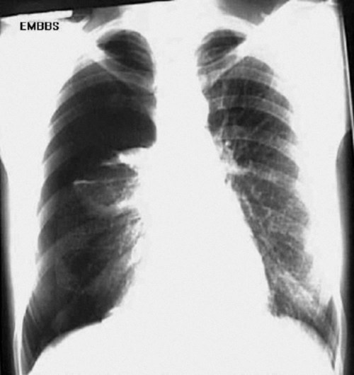
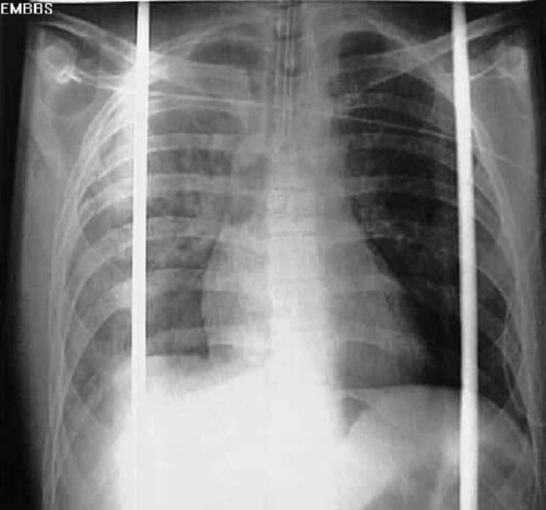
Full expansion of the lung fields is also important to evaluate. A pneumothorax causes part of the lung to collapse, creating a less dense empty space in the chest cavity that is devoid of any pulmonary or vascular markings (Figure 11-5). Conversely, a hemothorax or pleural effusion fills the chest cavity with fluid that is denser than normal lung tissue (Figure 11-6). Both of these abnormalities are evident on chest radiographs and can affect oxygenation, as discussed above.
Mediastinum
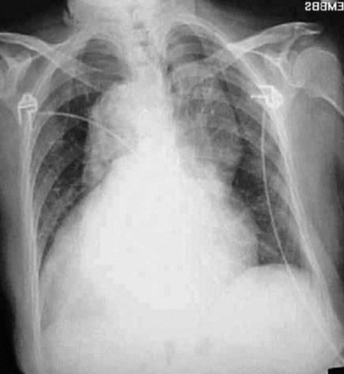
The width of the mediastinum is also important to evaluate. The mediastinal structures should be just wider than the thoracic spine. When the dense structures in this area are much wider than expected, a life-threatening aortic aneurism should be suspected. As the aortic arch widens, it projects a higher-density shadow over the upper left chest cavity that is visible on the radiograph (Figure 11-7).
Other Imaging Methods
Computed Tomography
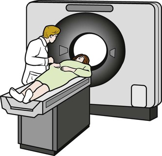
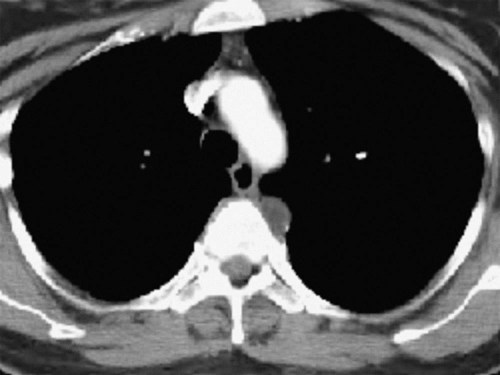
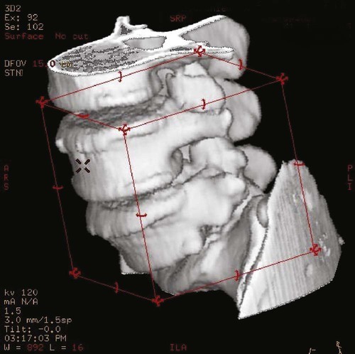
CT scans of the chest can be a useful diagnostic tool for certain diseases (Figure 11-8). Like standard radiographs, CT uses ionizing radiation, but it allows for rapid scanning in much more detail. The CT scan generates pictures that are “slices” through the patient in the axial plane (Figure 11-9). Although bone is visualized much better than soft tissues, a CT scan can still provide excellent images of the lungs, vascular structures, and heart. New software can produce three-dimensional images that show the anatomy beautifully (Figure 11-10), and the sensitivity of these machines can allow for the detection of very small amounts of calcification in the coronary arteries, which can be an indication of early heart disease. Newer “ultrafast” CT scanners can see more subtle changes in the coronary arteries because they take images so quickly that they seem to “stop” or “freeze” the action and movement of the heart. This results in clearer pictures and the ability to discern small details more accurately.4 Another modality, called spiral CT scan, provides higher resolution and more rapid images, making it very helpful in the diagnosis of pulmonary embolism, because it can visualize vessels with great precision. In certain cases, an iodine-based dye must be injected intravenously to enhance CT images. This dye can exacerbate renal disorders, and should thus be used with caution.
As CT scans become more and more precise, they are also used more frequently. This increased use raises a concern regarding the radiation exposure of patients undergoing these studies. Although radiation exposure is also a factor with conventional radiography of the chest, the level of exposure with computed tomography has been documented to be much higher. A typical chest CT will expose a patient to the radiation equivalent of 50 to 450 chest x-rays. This increase in radiation exposure had been linked to cancer development later in life, most notably in the pediatric population. Because of this risk, other chest imaging techniques may be considered if appropriate.5,6
Magnetic Resonance Imaging
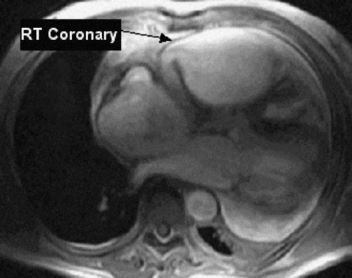
Magnetic resonance imaging of the chest can be performed to evaluate the soft tissues of the chest cavity.7 MRI has the advantage of using magnetic energy rather than ionizing radiation, so there is no harmful exposure for the patient. MRI scans also provide much higher-quality views of soft tissues than can be achieved by CT scans, but MRI is more expensive and takes nearly an hour to complete. A chest CT can be done in less than a minute, making it a better choice for evaluation of trauma (Figure 11-11). MRI is most useful when evaluating heart function/wall movement, vasculature of the heart and lungs, tumor size and staging, and respiratory movement of the muscles and diaphragm.4,8
Positron Emission Tomography Scan
Positron emission tomography (PET) scanning is a newer form of radionuclide imaging that helps show the function of organs rather than just their structure. For instance, the amount of radio-labeled glucose taken up by heart muscle cells can help clinicians determine whether the muscles have died after a myocardial infarction or whether they are still alive. This makes the PET scan a crucial decision-making tool: if the post-MI heart muscle cells are alive, they would benefit from bypass surgery, whereas if they are dead, bypass surgery would not be worthwhile. This modality is also very helpful in the localization of tumors in the chest cavity; these tumors are highly metabolic and have high uptake of the radionuclide, thus “lighting up” on a PET scan.9
Ultrasound
Ultrasound is an imaging modality commonly used in the abdomen, but because the sound waves bounce off bone, it is much less useful in the chest cavity. Ultrasound is sometimes used to identify pockets of fluid during thoracocentesis, but a CT scan is more commonly used whenever the precise placement of a needle in the chest is necessary. Ultrasound can also be useful to assess cardiac function via a modality known as transesophageal ultrasound.10
[/level-membership-for-cardiovascular-category][not-level-membership-for-cardiovascular-category]
Imaging of the Chest
Wilhelm Roentgen discovered the x-ray in 1895 and won the very first Nobel Prize in physics (1901) for this discovery.1 Since that time, radiography has been used in medicine to image the chest structures. Ionizing radiation has its disadvantages, however, as Thomas Edison learned when his laboratory assistant, Clarence Daley, became the first scientist to die of radiation exposure in the United States.1 By the 1940s, ultrasound was being used as a way to image the body using nonionizing radiation.1 Computed tomography (CT) was developed in the 1970s, and magnetic resonance imaging (MRI) in the 1980s.1 All these methods have been used to image the chest, and each offers distinct advantages and disadvantages for the patient and the clinician.
Most imaging machines still use film to capture the image, but newer systems are using digital formats. In either case, the basic methods are similar: x-rays are generated when the anode of an x-ray tube is bombarded with electrons from the cathode of the tube. The collision gives off energy in the form of x-radiation, which travels out of the tube and through the patient, then hitting the imaging cassette. The cassette contains film or a digital imaging sensor. The image is then processed by a digital processor or a film developer (Figure 11-1).
The darkest images on a film (also called radiolucent areas) represent pockets of air within the body. Fat is denser than air, and it produces a dark-gray image. Muscle and other soft tissues are more dense and produce a much lighter gray image. Finally, bone is the most dense natural substance in the body and produces a white image. Metallic objects are even more dense (also called radiopaque) than bone and produce a pure white image (Figure 11-2).
Soft tissues and extrathoracic structures: soft tissues (ST), breast shadows, (BS), diaphragm (D), liver (L), and fundus of stomach (F)
Bony thorax: ribs (RI), vertebrae (V), scapulae (S, seen best on PA), clavicles (C, seen best on PA), and sternum (S, seen best on lateral)
Mediastinal structures: mediastinum (M), trachea (T), carina (CA), aortic knob (AK), heart (H), anterior clear space (ACS, seen best on lateral), and hilus of lungs (HI)
Lung fields: hilus of lungs (HI), pulmonary vessels (arise from hilus and branch outward), costophrenic angles (CPA), and lung apices (LA, seen best on PA) (A from GE Healthcare.)
Figure 11-2, A, demonstrates all the different densities. This lateral view of the knee shows metal from a total knee replacement, along with bone, muscle, fat, and on either side of the patient’s knee, air.2
The x-ray image is a summation of all the densities that the x-rays have passed through. The different layers of tissue that are on top of one another are flattened into a single two-dimensional image. Sometimes the various densities lie next to one another and are easily distinguished in the image. Other times the two densities overlap one another and are blurred together in the image. For this reason, the patient is usually positioned so that two or more images can be taken at a right angle to one another. This allows structures that are overlapping in one orientation to be seen side-by-side with the other orientation.1,3
The Radiograph and Its Evaluation
Evaluation for Pathology
Overview
After verifying the technical aspects of the images, the diagnostic evaluation can begin. It will help to first review the different projections that have been taken (Table 11-1
[/not-level-membership-for-cardiovascular-category]
