General Principles of Mechanical Ventilation
INDICATIONS FOR MECHANICAL VENTILATION
Continuous Mandatory Ventilation
Synchronized Intermittent Mandatory Ventilation
OTHER MODES OF MECHANICAL VENTILATION
POSITIVE END-EXPIRATORY PRESSURE
MONITORING THE VENTILATED PATIENT
MAINTAINING SUPPORT OF THE VENTILATED PATIENT
WEANING FROM MECHANICAL VENTILATION
Management of the mechanically ventilated patient is a cornerstone of critical care training and practice. The institution of mechanical ventilation can be a lifesaving measure. However, the mechanical ventilator also has potential for great harm and, in and of itself, does not reverse underlying disease. Limiting iatrogenic injury from ventilator-induced lung injury (VILI) should take high priority, along with acceptable levels of oxygenation and ventilation. The clinician should be aware of basic and advanced principles involving mechanical ventilation, allowing flexibility when applying evidence-based practices to the individual patient. Knowledge of guidelines and large clinical trials is vitally important, and the consideration of patient trajectory, individual physiology, timing of therapy, and severity of illness will make tailoring the ventilator prescription most effective.1
History
Hippocrates (460-370 BC) likely gave the first description of endotracheal intubation in his “Treatise on Air,” in which he states that “One should introduce a cannula into the trachea along the jawbone so that air can be drawn into the lungs.”2 In 1530, Paracelsus (1493-1541) used a fire bellows connected to a tube inserted into a patient’s mouth as a ventilator device.3 The first known mechanical device designed specifically to provide ventilation for the patient was the foot pump developed by Fell and O’Dwyer in the 1880s.4
The first generation of mechanical ventilators focused primarily on the intermittent delivery of a bulk volume of gas to the patient with limited monitoring.5 Negative-pressure ventilators were invented and applied a negative pressure around the body or chest cavity. Two classic devices that provided negative-pressure ventilation were the iron lung and the chest cuirass or chest shell.6 Iron lungs were widely used during the poliomyelitis epidemics of the 1930s and 1940s. These devices encased the patient from the neck down and applied negative pressure around the patient to expand the lungs. The chest cuirass was intended to alleviate the problems of patient access and “tank shock” that occurred secondary to venous pooling during the application of negative pressure associated with iron lungs.7 Although the chest cuirass improved patient access and decreased the potential for tank shock, ventilation with this device was limited by the difficulties in maintaining an airtight seal between the shell and the patient’s chest wall.
After the polio epidemic of the 1960s, the era of respiratory intensive care emerged, as positive-pressure ventilation via an artificial airway became commonplace.6 Controlled mechanical ventilation eventually led to assisted modes of support, and positive end-expiratory pressure (PEEP) was introduced in the late 1960s. The improvements in mechanical ventilators came about as understanding was gained in manipulating variables of flow and pressure for patient benefit. Further technical evolution of ventilators included advances such as intermittent mandatory ventilation, and synchronous intermittent mandatory ventilation. Modern ventilators now boast microprocessors that serve both in the operating mechanism of the device and in the monitoring systems, enabling automatic adjustment of most aspects of the mechanical breath being delivered.
Mechanical Ventilation
Basic Concepts
 ) mismatch occurs when areas of the lung are perfused but either poorly ventilated (low
  ) or not ventilated at all (shunt). The latter is an intrapulmonary (IP) (capillary) shunt. Shunt may also be intracardiac (anatomic). Venous admixture, as a measure of less than fully oxygenated blood after passing through the lung, includes both low
  areas of lung and IP shunt. Normal venous admixture is about 2% to 5%. Mechanical ventilation may increase the venous admixture to approximately 10% in the normal individual. Mechanical ventilation usually decreases venous admixture in alveolar lung disease, such as acute lung injury (ALI), improving the distribution of ventilation especially in previously underventilated lung areas. Pressures greater than alveolar opening and closing pressures expand the collapsed alveolus and prevent its collapse, respectively. However, if positive-pressure ventilation produces overdistention, redistribution of pulmonary blood flow to unventilated regions may occur, resulting in hypoxemia. Dead space refers to areas of the lung with a higher
  ratio. Anatomic dead space is the volume of the conducting airways of the lungs, about 150 mL. Alveolar dead space refers to alveoli that are overventilated relative to perfusion; it is increased by any condition that reduces pulmonary blood flow, such as pulmonary embolism (PE) or with overdistention of the lung. Mechanical dead space refers to the rebreathed volume of the ventilator circuit; this volume behaves like an extension of the anatomic dead space. Mechanical ventilation can also increase dead space if it leads to overdistention.
Although modern ventilators have evolved into complex machines, the basic premise remains: a ventilator is designed to replace or augment a patient’s muscles in performing the work of breathing.8 Ventilators use input power (electricity or compressed gas) to ventilate the lungs. To generate a breath (whether it be spontaneous or positive pressure), a pressure gradient must be generated from the airway opening to the alveoli. The volumes delivered and pressures generated largely depend on the mechanical properties of the respiratory system: the lungs and chest wall as well as the abdomen.8 Each of these components has mechanical properties that determine the overall behavior of the respiratory system. Although the respiratory system can be quite complex, the main variables of interest are pressure, flow, and volume. The ventilator must generate a pressure to cause flow through an open circuit and therefore increase lung volume.9 The pressure required to do this reflects a combination of the pressures to inflate the lung and chest wall. This can be illustrated by the equation of motion:9,10

Compliance describes the ease or difficulty of the respiratory system to expand in response to a delivered pressure and volume. Simplistically, compliance is defined by the change in volume (ΔV) divided by the change in pressure (ΔP), and the compliance of the respiratory system (CRS) is ΔV/ΔPalveolar. Elastance is the inverse of compliance, or the ratio of pressure change to volume change, and describes the tendency to recoil. Resistance describes the impedance to airflow through the respiratory system, or the ratio of pressure change to flow change. The elastic load is the pressure required to overcome the elastance of the respiratory system, and the resistive load is the pressure required to overcome flow resistance of the ventilator circuit, endotracheal tube, and airways.8
The Ventilator Circuit
The ventilator circuit consists of plastic tubing connecting the artificial airway or mask with the mechanical ventilator. Within the circuit may reside humidifiers, devices for the delivery of aerosolized medications, filters, suction catheters for secretion clearance, and heated wires.11 The length and compliance (2-3 cm3/cm H2O) of the ventilator circuit are responsible for a volume of gas contained within the circuit, termed the compressible volume. This is partly responsible for the discrepancy between the set tidal volume delivered and the expiratory volume measured and displayed by the ventilator. The ventilator circuit also adds resistance to the system, but is minimal when compared to either the patient’s inherent mechanics or the endotracheal tube. Although frequently colonized with bacterial pathogens, the routine change of the ventilator circuit for infection prevention (e.g., ventilator-associated pneumonia) is not recommended.
An HME, which is placed between the artificial airway and the ventilator circuit, may be used to replace the traditional heated humidifier. During exhalation, moisture and heat from the patient are absorbed into the honeycomb structure of the exchanger and are transferred back to the patient during the next inhalation. Ventilator circuits with bacterial-viral filtering HMEs cost less to maintain and are less likely to colonize bacteria than those with heated humidifiers.12,13 Contraindications for use of an HME are thick or large amounts of secretions, minute volume exceeding 10 L/minute, body temperature less than 32° C, and need for aerosolized medications.14
Alarms and Safety
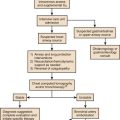
Current ventilators are equipped with monitors that constantly or periodically assess the ventilator’s operation and the patient’s status (Fig. 9.1). These monitors are usually associated with alarms that visually or audibly notify the operator of any variation from the preset norm. Ventilator alarms can warn of potentially life-threatening events, must have an appropriate level of sensitivity and specificity, and must be evaluated clinically and in a clinical context.15 There are some alarms related to power input (e.g., low battery, loss of power, loss of air supply) and control circuit (e.g., nonfunctioning ventilator, incompatible settings), but most alarms are related to measured output, such as pressure, volume, and flow.8
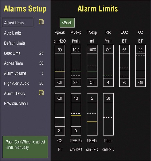
High-pressure alarms are triggered by patient factors (such as decreased compliance and increased resistance of the respiratory system) or by ventilator circuit malfunction (obstruction or kinking of the endotracheal tube). Low-pressure alarms are generally secondary to a leak in the system (ventilator circuit, endotracheal tube or cuff) or patient (large pressure loss from a bronchopleural fistula). A high expired volume alarm could be seen with improved pulmonary mechanics during pressure-control ventilation. Low expired volume could be secondary to patient-ventilator disconnect or a leak in the system or patient. A high-frequency alarm is secondary to either autotriggering or hyperventilation, and a low-frequency alarm indicates bradypnea or apnea.8,15
Automatic Tube Compensation
Traditionally, most clinicians apply some amount of pressure support during inspiration to compensate for the increased work of breathing related to artificial airway resistance. The amount of pressure support needed to counterbalance this resistance is highly variable, depending not only on the internal diameter of the endotracheal tube but also on flow, bend of the tube, and changing demands of the patient. This variability makes one level of pressure insufficient to meet these changing demands.16
Automatic tube compensation (ATC) compensates for endotracheal tube resistance via closed-loop control of calculated tracheal pressure. A ventilator with ATC compensates for the pressure drop across the endotracheal tube during inspiration by increasing the airway pressure and during expiration by decreasing airway pressure according to actual gas flow.17–19 This technique uses a continuous calculation of the flow-dependent drop in pressure across the endotracheal tube. ATC is similar to PSV, but the pressure applied by the ventilator varies as a function of endotracheal tube resistance and flow demand. Most of the interest in ATC revolves around eliminating the imposed work of breathing during inspiration. During expiration, however, ATC may also compensate for that flow resistance by lowering the pressure in the expiratory limb transiently from its PEEP setting, helping reduce effective expiratory resistance and auto-PEEP.17,20 In addition to overcoming the work of breathing imposed by the artificial airway, ATC may improve patient-ventilator synchrony by varying the flow commensurate with demand and may reduce air trapping by compensating for imposed expiratory resistance. During weaning trials, this technique may allow a more reliable prediction of patient performance when the tube is removed.
Indications for Mechanical Ventilation
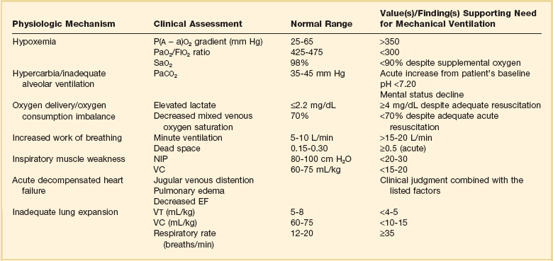
Mechanical ventilation is instituted for a number of reasons (Table 9.1).21 Most commonly, these indications are a combination of a failure to adequately oxygenate, ventilate, or meet the metabolic demands of a physiologically stressed patient. Clinical indicators such as tachycardia, arrhythmias, hypertension, and tachypnea, use of accessory respiratory muscles, diaphoresis, and cyanosis are used to diagnose respiratory distress. Type I respiratory failure is hypoxemic respiratory failure, defined as a partial pressure of oxygen in arterial blood (PaO2) less than 60 mm Hg. Type II respiratory failure is hypercarbic respiratory failure, defined as PaCO2 greater than 50 mm Hg, if elevated from patient baseline and associated with acidosis.22 Blood pH is generally a better indicator than PaCO2 for adjusting minute ventilation. Hypercapnia should not prompt aggressive intervention if pH remains acceptable and the patient remains alert. Hypercapnia is generally well tolerated, but this clearly depends on the underlying pathophysiology and comorbid conditions of the patient (e.g., right ventricular dysfunction). However, a sustained pH of 7.65 or greater or 7.10 or less is often considered sufficiently dangerous in itself to require control of minute ventilation by mechanical ventilation. Mechanical ventilation may also be instituted to maintain normal blood pH, decrease work of breathing, assist left ventricular function in the setting of acute decompensated heart failure, or for airway protection in the setting of toxic overdose, traumatic brain injury, or any other significant acute central nervous system illnesses. Box 9.1 suggests guidelines for setting basic operating parameters in a mechanical ventilator.
Mechanical Breath Generation
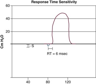
Triggering represents the change from expiration to inspiration and occurs either because of a drop in circuit pressure or diversion of flow (when patient triggered), or because of elapsed time. Sensitivity refers to a preset threshold of pressure or flow. When this threshold is reached, a mechanical breath is delivered. This threshold can be adjusted, and is usually set at −1 to −2 cm H2O. If sensitivity is set too low, the ventilator will be triggered by any process that causes the airway pressure to drop below the set threshold. Such processes include patient motion, external compression, gastric suctioning, and air leaks in the circuit. Conversely, if the threshold is set too high, the work of breathing increases, as the patient must make a significant effort to overcome the threshold limit for inspiratory flow to occur. In the setting of pressure triggering, airway pressure is reduced (by patient effort) in the proximal circuit, the expiratory valve closes, pressurization of the inspiratory limb of the circuit occurs, and the patient receives a breath. Flow sensing was developed as an alternative to pressure triggering to reduce the delay in response time between neural input from the patient and delivery of gas volume by the ventilator.23,24 In the setting of flow triggering, the patient’s inspiratory effort induces a disruption of the constant flow in the ventilator inspiratory circuit. This change in flow signals the expiratory valve to close and for the ventilator to deliver the next breath. Flow triggering was initially demonstrated to decrease the work of breathing when compared to pressure triggering. However, with improvement in response time, monitoring, and feedback, pressure and flow triggering are similar in this regard.25,26 Figure 9.2 is a representation of patient effort and ventilator response time.
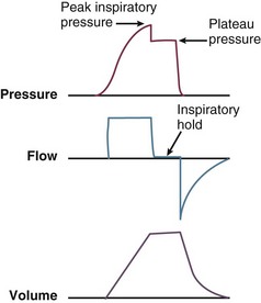
During inspiration, pressurized gas is channeled from the ventilator to the patient after the exhalation valve closes. This phase can be controlled by how one sets flow or pressure in the ventilator proximal to the open inspiratory valve. For example, volume-assist control is flow controlled and pressure-assist control is pressure controlled. Choice of control variable is largely the discretion of the clinician, as either can be manipulated to achieve set goals. It should be noted, though, that in volume-targeted ventilation, excessive airway pressures can arise secondary to worsening pulmonary mechanics. In this situation, the pressure alarm will cause a pressure limit to cycle to expiration. At the end of inspiration in volume-targeted ventilation, an inspiratory hold maneuver can be performed (Fig. 9.3), which can distinguish the peak airway pressure from the plateau pressure (because flow is stopped, resistance is negligible). In pressure-targeted ventilation, minute ventilation is not guaranteed. It is a function of the compliance and resistance of the respiratory system. The clinician therefore should monitor these physiologic changes closely to avoid untoward changes in either airway pressure or PaCO2 levels.
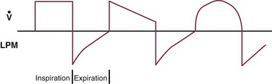
With pressure control and pressure support (PS) breaths, the pattern of inspiratory flow is a natural decelerating pattern as the pressure gradient for flow decreases as pressure rises in the patient’s lungs. The pattern of inspiratory flow with a flow-controlled breath is naturally square but can be computer altered to be decelerating or sinusoidal (Fig. 9.4). A square inspiratory flow pattern results in a rapid rise to a preset level (set by the clinician) followed by constant flow until cycling occurs. Decelerating flow results in a rapid rise to a maximum level followed by a gradual decrease until cycling. Sinusoidal flow pattern most closely represents normal physiologic breathing. It results in flow that gradually increases and then decreases during inspiration. The choice of inspiratory flow pattern should be based on patient characteristics, and a few common clinical scenarios should be familiar to the clinician. Square flow over time results in a shorter inspiratory time (I time), and therefore longer expiratory time (E time). For this reason it may be preferred in patients with obstructive physiology (chronic obstructive pulmonary disease [COPD] or asthma).27,28 It is also usually tolerated better in patients with demand for high minute ventilation, such as severe metabolic acidosis or elevated ICP. In this situation, there is a potential for dyssynchrony to occur during the progression of the inspiratory phase if decelerating flow is chosen. The tradeoff is higher peak airway pressures with a square waveform, which may be ameliorated if it leads to a reduction in hyperinflation and iPEEP. Decelerating flow results in a longer I time and likely a better distribution of flow. With pulmonary pathophysiology involving heterogeneous distribution of injury (ALI as the prototype example), decelerating flow is likely the best choice, as the longer I time can lead to more homogeneous distribution of ventilation. The distribution of ventilation can be quite different when the flow pattern changes. A decelerating flow pattern yields the most even distribution under most abnormal airway conditions.29 Studies have also demonstrated that a decelerating flow pattern improves the geographic distribution of lung vibration as a presumed surrogate of airflow.30 The length of inspiration depends on several factors. In the pressure control mode of ventilation, the clinician directly controls the I time and I : E ratio. With pressure support the patient primarily controls I time. In flow-controlled (volume-targeted) ventilation, the I time is a function of set tidal volume (VT) and flow rate (VT/inspiratory flow rate) as well as flow wave characteristics (shape). The end-inspiratory alveolar pressure, as measured by an end-inspiratory hold, is the same for a given tidal volume regardless of the type of ventilator breath.
 , flow.
Ventilator Modes
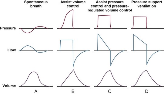
A ventilator mode describes ventilation over time and a set of specific combinations of breath characteristics delivered to a patient, including types of breaths, phase variables, and mandatory versus spontaneous breaths.16 Clinician familiarity, unit, and institutional practice patterns determine to a large extent the mode that is employed. Also, data showing definitive improvement in clinically relevant outcomes when comparing one mode to another are lacking. Patient need and response to therapy should guide mode selection. Table 9.2 summarizes the features of some of the modes of mechanical ventilation, and Table 9.3 lists some of their advantages and disadvantages. Figure 9.5 also shows some characteristic waveforms of various modes of mechanical ventilation.
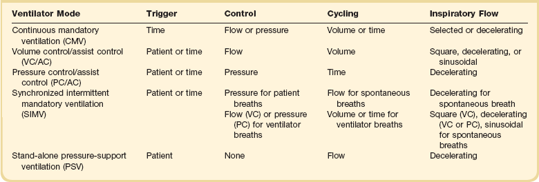
Table 9.3
Potential Advantages and Disadvantages of Selected Modes of Mechanical Ventilation
| Mode | Advantage(s) | Disadvantage(s) |
| Controlled mechanical ventilation (CMV) | Rests muscles of respiration | Requires use of heavy sedation/neuromuscular blockade |
| Assist volume control (AVC) | Reduced work of breathing Guarantees delivery of set tidal volume (unless peak pressure limit alarm is exceeded) |
Potential adverse hemodynamic effects May lead to inappropriate hyperventilation and excessive inspiration pressures |
| Assist pressure control (APC) | Allows limitation of peak inspiratory pressures | Same as for AVC Potential hyperventilation or hypoventilation with lung resistance/compliance changes |
| Synchronized intermittent mandatory ventilation (SIMV) | Less interference with normal cardiovascular function | Increased work of breathing compared with assist control Patient may find it difficult to adjust to two different types of ventilator breaths |
| Stand-alone pressure-support ventilation (PSV) | Patient comfort Improved patient-ventilator interaction Decreased work of breathing |
Apnea alarm is only backup Variable patient tolerance |
Stand-Alone Pressure Support Ventilation
This mode of ventilation is patient triggered, pressure controlled, flow cycled, with a decelerating flow inspiratory waveform. Cycling to expiration typically occurs when flow rate decreases to a set percentage of inspiratory flow (typically 25% of initial inspiratory flow). However, if there is a leak in the system, inspiratory flow may never decrease to the cycle threshold. In this situation, for safety purposes, flow can be time cycled as well. During inspiration, the ventilator will adjust flow to maintain the preset pressure, and tidal volume is dependent on patient effort, as well as the mechanics of the respiratory system. Pressurization rate to the goal pressure is determined by the rise time, which can be adjusted on many ventilators. If the rise time is set too low, increased work of breathing can occur; if set too high, preset pressure may be exceeded (overshoot), causing early cycling to expiration. PSV is effective at decreasing patient effort and work of breathing.31–33 Data suggest that most clinicians view PSV as a weaning mode of mechanical ventilation, despite its being fully capable of appropriate full support in patients with respiratory failure intact respiratory drive.34
Dual Control Modes
The preceding modes of mechanical ventilation are classically referred to as “conventional” ventilator modes, which is purely arbitrary. Dual control modes of ventilation manipulate pressure or volume on either a breath-to-breath basis or within the same breath. Breath-to-breath modes include volume support (VS) and pressure-regulated volume control (PRVC), also called “pressure control volume guarantee.” VS is PSV (pressure limited, flow cycled) that uses tidal volume as a feedback to adjust the pressure support level.16 PRVC is pressure control ventilation (pressure limited, time cycled), but uses tidal volume as a conditional variable to adjust pressure to achieve desired tidal volume.
Other Modes of Mechanical Ventilation
Airway Pressure Release Ventilation
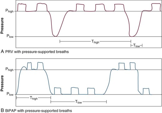
Airway pressure release ventilation (APRV) has been described in the literature since 1987.35 It is a time-triggered, pressure-controlled, time-cycled mode of mechanical ventilation that exactly resembles AC/PC with very extended I : E ratios if the patient is not spontaneously breathing.36,37 It has been described as continuous positive airway pressure (CPAP) with an intermittent time-cycled release phase to a set lower pressure. Whereas conventional modes of mechanical ventilation elevate airway pressure up from a set baseline to accomplish tidal ventilation, APRV employs very high I : E ratios to maintain mean airway pressure, and brief deflations to accomplish ventilation. When APRV is used in acute respiratory distress syndrome (ARDS) (primary use) short Tlow is used whereas this mode can be used in patients without ARDS with longer Tlow and is often called “bilevel positive airway pressure” (BiPAP) in that circumstance (Fig. 9.6). The expiratory valve in APRV also facilitates spontaneous breathing throughout the ventilatory cycle, facilitating ventilation. Because this mode is primarily used with ARDS with long Thigh and very short Tlow, breathing occurs primarily during Thigh. Pressure high (Phigh) is the baseline airway pressure that occupies most of the ventilatory cycle. Pressure low (Plow) is the release pressure and is set at 0 cm H2O. Time high (Thigh) is the length of time for which Phigh is maintained and Tlow is the length of time for which Plow is maintained. This is primarily semantics, but the term APRV implies longer I : E ratios than BiPAP, and a Plow setting of 0 at all times.
Although outcome data are lacking compared to conventional ventilation using protective lung strategies, the reported advantages of APRV include sustained alveolar recruitment with improved oxygenation, higher mean airway pressures accomplished with lower Ppeak and Ppl, spontaneous breathing throughout the ventilatory cycle, and decreased use of sedation and neuromuscular blockade in severe ARDS.37 The maintenance of spontaneous breathing may improve  matching by preferential ventilation of dependent lung regions, and the higher mean airway pressure, relative to Ppeak and Ppl, may limit VILI.
Alveolar recruitment is a pan-inspiratory phenomenon and alveoli that are recruited are more compliant than recruiting or nonrecruited alveoli. With prolonged elevated pressures, APRV likely recruits alveoli, which require a longer inflation with higher threshold opening pressures.36,37 Sustained inflation maintains recruitment, decreases shunt and dead space, and employs the more compliant expiratory limb of the pressure-volume (PV) curve. Ventilation is determined by the stored kinetic energy at the high pressure, the intermittent release phase, and is augmented by spontaneous breathing. Although minute ventilation is decreased with this mode of ventilation, ventilation is also improved by a decrease in dead space.
Clinical data are limited but have shown improved oxygenation, less shunt and dead space, as well as decreased need for sedation and neuromuscular blockade.37–41 Data on clinically relevant outcomes, such as mortality rates, mechanical ventilation days, and ICU days, are limited. This mode remains physiologically attractive for its effects on oxygenation and potential to limit VILI, but no specific recommendations can be made, given the lack of good outcome data.
High-Frequency Oscillatory Ventilation
High-frequency oscillatory ventilation (HFOV) is very different from conventional bulk flow ventilation and uses respiratory frequencies much higher and tidal volumes much lower than conventional modes. It is similar to APRV in that it aims to elevate mean airway pressure to maximize recruitment and oxygenation, while limiting Ppeak.42 Oxygenated, humidified gas (bias flow) passes in front of an oscillating membrane and generates very small tidal volumes at very high respiratory rates. This is actively driven by a piston pump that oscillates the diaphragm. This produces sinusoidal or somewhat erratic pressure waves that are actively driven in both inspiration and expiration (unique in that expiration is not passively driven by elastic recoil). This component is created by the backward movement of the diaphragm or piston of the oscillator. Resistance valves are used to apply a constant distending airway pressure, over which small tidal volumes are superimposed at a high respiratory frequency; in this fashion, it uncouples, for the most part, oxygenation and ventilation.
Given the fact the tidal volume is often less than anatomic dead space, HFOV relies on gas transport mechanisms much different from those employed by bulk flow ventilation. These mechanisms include some convective gas transport, but also molecular diffusion, pendelluft, coaxial flow, and Taylor dispersion.43
When initiating HFOV, the patient’s endotracheal tube should be verified to be patent, as heavy secretions or kinks in the endotracheal tube will significantly harm ventilation. The mean airway pressure should be set at about 5 cm H2O higher than that achieved with conventional settings. The bias flow delivers fresh gas into the ventilator circuit at 40 to 60 L/minute and helps maintain mean airway pressure.43 The power control allows adjustment of amplitude (Δ pressure), which is set high enough to elicit vibrations of the patient to the lower abdomen or midthigh. Frequency helps determine ventilation and is set typically at 3 to 5 Hz. It should be noted, however, that at low frequencies, higher tidal volumes and bulk flow can be achieved, which assists in ventilation (and may contribute to VILI). Percentage of I time is set at 33% or 50%, depending on ventilation goals.
This effect would be predicted to be most beneficial when applied early in the course of severe ALI.42,44 Recently completed clinical trials of the comparison of HFOV with ARDS net setting standard ventilation in patients at the onset of moderate or severe ARDS showed no benefit of HFOV, and one of the two trials showed increased mortality rate in the HFOV arm.44,45 This would imply consideration of HFOV use only as salvage therapy in ARDS. The clinician should note that patients ventilated with HFOV will require heavy sedation or neuromuscular blockade.
Effort-Adapted Modes of Mechanical Ventilation
PAV is a mode of partial support in which ventilator assist is delivered in proportion to patient effort. A defined level of assist, or unloading, relieves the resistive and elastic burden of the respiratory system.46,47 The ventilator responds to the mechanical output of the patient and will amplify patient effort with a preset proportional amount of pressure support. The theory behind PAV is based on the equation of motion; based on changes in flow and volume, flow-proportional and volume-proportional pressure support is given. A percentage of effort is set by the clinician, and applied airway pressure develops as a function of volume to overcome elastance or a function of flow to overcome resistance.46 Reported benefits of PAV include improved synchrony, better physiologic breathing pattern, and improved sleep quality.48–54 A limitation of PAV is that it relies on the mechanical output from the patient, and therefore, continuous knowledge of the elastic and restrictive properties of the patient is a necessity. If PAV incorrectly estimates the mechanical properties, the ventilator may overassist, causing delayed inspiratory ending (“runaway phenomenon”). This problem has been improved by the development of PAV+ (PAV with load adjustable gain).
NAVA is similar to PAV in that it is also an effort-adapted mode of partial assist. Unlike PAV, which responds to the mechanical output from the patient, NAVA responds to the neural input from the electrical activity of the diaphragm (Edi). Pressure is applied in a linear proportion to Edi, and this requires the placement of an esophageal electrode (similar to nasogastric tube placement). The ventilator is triggered based on Edi or conventional signals (whichever comes first), therefore improving synchrony, as the time delay from patient effort to breathe is very brief. In addition, the amount of ventilator assistance varies based on Edi. As such, to achieve greater assistance, the patient must increase Edi. Reported benefits include improved synchrony55–59 and preserved variability in breathing pattern.46,60,61 High NAVA levels and high Edi may result in high inspiratory pressures and tidal volume delivery, especially in patients with unstable respiratory patterns or high respiratory drive.62,63
ASV ensures a set target minute ventilation based on measurements of the patient’s E time constant and dynamic compliance, along with preset information of predicted body weight, minimum minute volume limit, and a pressure limit.46 The ventilator attempts to minimize the work of breathing by combining the most effective combination of rate and tidal volume, while limiting pressure support. ASV potential benefits include decreased work of breathing and improved patient-ventilator interaction.
Positive End-Expiratory Pressure
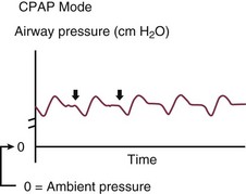
CPAP maintains airway pressure above atmospheric pressure throughout the respiratory cycle by pressurization of the ventilator circuit. In mechanically ventilated patients, the purpose of CPAP is to achieve therapeutic PEEP in the presence of ALI or pulmonary edema (Fig. 9.7). In these patients PEEP serves to restore functional residual capacity (FRC), reduce IP shunt, shift ventilation to a more compliant portion of the PV curve, and prevent end-expiratory volume loss (derecruitment).64 PEEP recruits previously nonaerated lung tissue and homogenizes regional distribution of tidal ventilation. The net effect on gas exchange reflects the balance between recruitment and overdistention. In the setting of obstructive physiology or expiratory flow limitation, PEEP serves less to improve oxygenation, but more to improve patient-ventilator synchrony and triggering.27,28,65
PEEP is not without side effects. Given the heterogeneous distribution of lung injury in ALI/ARDS, PEEP can overdistend more compliant lung units, contributing to VILI.66 If PEEP leads to overdistention, it can augment dead space, increase pulmonary vascular resistance, and cause right-sided heart dysfunction. It can also decrease venous return and, in the setting of volume depletion, decrease cardiac output.
The optimal way to set PEEP is debated and controversial, as is the optimal level of PEEP to use.67–82
See Chapter 11 for a detailed discussion of PEEP application in ARDS.
Monitoring the Ventilated Patient
Hemodynamics
Positive-pressure ventilation causes predictable physiologic changes and cardiopulmonary function is intimately linked—respiratory function alters cardiovascular function and vice versa.83,84 The venous system is a low-pressure reservoir that contains about three fourths of our total blood volume.83,85 This can be divided into the stressed and unstressed volume. The stressed volume contributes to the return of blood to the heart. The right ventricle’s main function is to accept venous return and eject the optimal amount of blood into a (usually) highly compliant pulmonary vascular system.84–87 This maintains a low right atrial pressure, thereby maximizing venous return and overall myocardial performance. A positive-pressure breath increases lung volume and increases intrathoracic pressure, which increases juxtacardiac pressure and therefore right atrial pressure. This can decrease venous return and therefore left ventricular preload several cardiac cycles later. At the same time, positive-pressure ventilation decreases left ventricular afterload by increasing the juxtacardiac pressure, therefore assisting ventricular contraction.
With respect to the mechanical ventilator, arterial blood pressure monitoring is commonplace in all intensive care units (ICUs). Though noninvasive cuff measurements can be adequate, invasive, continuous monitoring is much more informative when ventilator settings are dynamically changing. A fall in blood pressure temporally related to a ventilator change is a fairly specific indicator of a drop in cardiac output.85 A narrow pulse pressure may indicate relative hypovolemia, although a widened pulse pressure may point to vasodilation or regurgitant cardiac valve disease. Pulse pressure variation (secondary to previously described heart-lung interactions) in mechanically ventilated patients is also the most accurate predictor of determining preload responsiveness.88 Central venous pressure (CVP) is a reflection of right atrial pressure, and normally is low to maximize venous return. Despite the commonality of its use in determining volume status and preload responsiveness, data and physiology have shown that to be inaccurate.89 This does not indicate the measurement of CVP is not of value. The absolute value and morphologic appearance (e.g., large v wave) of the CVP tracing can serve as valuable surrogates for right ventricular function, and an inspiratory fall in CVP can indicate preload responsiveness.90 There are multiple other hemodynamic variables that could be measured in the mechanically ventilated patient, such as pulmonary artery occlusion pressure and mixed venous oxygenation, and these should be based on individual patient characteristics.
Pulse Oximetry
Pulse oximeters determine oxygen saturation by determining arterial blood light absorption at 660 nm and 940 nm wavelengths. The ratio of absorption of these two wavelengths is then calibrated against computer-stored algorithms to determine the oxygen saturation. Pulse oximeters are quite accurate at their upper range, but lose accuracy at lower oxygen saturations, require a good pulsatile signal, and have other limitations. These limitations include hypoperfusion, motion artifact, dyshemoglobinemias, ambient light, certain intravenous dyes, and deeply pigmented skin. Pulse oximetry is virtually ubiquitous in the ICU. Its use includes detection of hypoxemia, monitoring response to ventilator changes (such as PEEP setting), weaning FIO2, and as a surrogate for pulmonary gas exchange.91
 relationships or changes in cardiac output; the morphologic pattern of the waveform can be altered in patients with endobronchial intubation, expiratory flow limitation, and ventilator dyssynchrony.
Maintaining Support of the Ventilated Patient
Sedation and Analgesia
Critically ill patients who are mechanically ventilated often require sedative and analgesic drugs, and pain is common among ICU patients.92 The ideal sedative and analgesic regimen would provide adequate sedation and pain control, rapid onset of action, rapid recovery after discontinuation, minimal systemic accumulation, and minimal adverse effects—without raising health care costs.93 The primary aim of these medications is to reduce the physiologic stress of respiratory failure and to improve the tolerance of mechanical ventilation. As more patients survive acute illness, the importance of goal-oriented sedation and analgesia has emerged, and the deleterious side effects of these medications is evident.94
Historically, mechanically ventilated patients have been treated with continuous infusions of benzodiazepines, opiates, and propofol.95–97 Unfortunately, emerging data point to increased side effects associated with these medications, such as delirium, increased mechanical ventilation days, increased lengths of hospital stay, and higher mortality rate.94,98,99 This has prompted interest in novel regimens with agents such as dexmedetomidine, an α2-agonist with sedative and analgesic properties. Data have shown that dexmedetomidine use is associated with a reduction in delirium, improved cognitive function, and decrease in mechanical ventilation days.100–104
Positioning
There is no optimal position for an individual patient and certainly no evidence-based gold standard. Predictable physiologic changes occur in patients when placed in the supine position, including reduced FRC, alteration in pleural pressure, reduced lung compliance, and change in  matching. The supine position should be avoided, as it is a risk factor for ventilator-associated pneumonia (VAP).105,106 In patients with unilateral lung injury, the “good side” should be placed in the dependent position to optimize
  match. Patients with severe hypoxemia (PaO2:FIO2 ratio < 100) should be considered for prone positioning early in the course of ALI, as this will likely improve oxygenation and may offer survival benefit in this patient cohort.107
Weaning From Mechanical Ventilation
Shortly after a patient is endotracheally intubated to initiate mechanical ventilation, thoughts should turn toward liberation from the ventilator. The withdrawal of mechanical support is a continuum from intubation until hospital discharge.108,109 Depending on severity of illness, patient comorbid conditions, and critical care treatments needed, the timing of this may range from hours to weeks or months. There are several evidence-based guiding principles that shorten mechanical ventilation days across a broad cohort of critically ill patients.
The first step (and perhaps most important) in liberation from the ventilator is the targeted use of sedation, limitation of sedative and opioid infusions, and the monitoring for and aggressive treatment of delirium.94 Patients should also undergo daily interruption of sedative medications (SAT), which has been shown to decrease ventilator days and ICU length of stay.110 After awakening, the patient should be assessed for readiness to wean. The literature abounds with weaning predictors, all of which have modest sensitivity and specificity, including the frequency/tidal volume ratio.109 Given this, as opposed to weaning predictors, the patient should undergo an SBT based on common sense, overall clinical trajectory, lack of hypoxia, and hemodynamic stability. The SAT should be paired with an SBT, as the SAT-SBT pairing decreases ventilator days, shortens ICU and hospital length of stay, and improves mortality rate.111 An SBT can be conducted unassisted through a T-piece, on low-level PSV, or on CPAP, once or multiple times a day, and from 30 to 120 minutes; SIMV weaning is not recommended.112–117 If a patient fails an SBT, a reason for that failure should be sought and corrected. This could include sedation, weakness, delirium, respiratory muscle fatigue, or left ventricular dysfunction. Also, after failing an SBT the patient should be placed immediately on comfortable full mechanical support, as delaying this and prolonging the SBT to the point of respiratory muscle exhaustion can delay extubation. After passing an SBT, the patient should be extubated unless a reason exists to leave the endotracheal tube in place (e.g., no cough reflex and heavy pulmonary secretions). The ability to predict successful extubation is challenging, and if the clinician never experiences a reintubation, he or she is likely not extubating patients based on the best available evidence.
Complications of Mechanical Ventilation
Ventilator-Induced Lung Injury
Mechanical ventilation can be a lifesaving intervention. However, it has great potential for harm, and the clinician’s focus should extend beyond normalization of gas exchange to providing safe and physiologically sound mechanical ventilation. Perhaps nowhere is this demonstrated more significantly than with the concept of VILI. Most patients with ALI do not die of hypoxia, but rather multiple organ dysfunction syndrome (MODS).118–121 Applied airway pressures in patients with ALI distribute in a heterogeneous fashion, leaving more compliant lung units overdistended, and others collapsed and nonrecruited. Respiratory system compliance is related to the amount of normally aerated lung tissue that remains, the so-called baby lung.122 This heterogeneity leads to a maldistribution of ventilation, with some alveoli overdistended, others collapsed throughout the respiratory cycle, and others cyclically opening and closing. VILI is a spectrum, classically defined as barotrauma, atelectrauma, and volutrauma (stretch injury).123 All of these can lead to biotrauma, or the decompartmentalization of the inflammatory response secondary to increased alveolar epithelial-capillary endothelial permeability. This results in the release of biologic inflammatory mediators and the spread of injury to distant organs, causing MODS and death. VILI is much more complex than the preceding definitions and involves tissue stress and strain modifiers, complex molecular mechanisms, as well as gene activation and up-regulation.124,125
Human studies support the concept of VILI and the importance of a protective ventilation strategy with low tidal volumes and the use of PEEP. Low tidal volume ventilation is the only intervention shown to consistently improve outcome in ALI, and support for protective lung ventilation to decrease VILI from several well-conducted clinical trials exists.71,72,126 This includes data showing a decrease in inflammatory mediators in patients ventilated with a protective lung strategy. In the absence of a patient-specific factor to suggest otherwise, a protective ventilation strategy, consisting of low tidal volume ventilation, PEEP setting, and limitation of plateau pressure, should be attempted at all times. Emerging data suggest that these strategies should be employed not only in patients with ALI, but in all patients receiving mechanical ventilation, especially those with known risk factors for the development of ALI.127
Ventilator-Associated Pneumonia
One of the most frequent complications of mechanical ventilation is the development of VAP.128–139 VAP is discussed in Chapter 42.
Gastrointestinal Bleeding
Mechanical ventilation is a risk factor for gastrointestinal bleeding secondary to stress ulceration, trauma (especially traumatic brain injury), and major burns. Mechanical ventilation for longer than 48 hours is regarded as the most frequent risk factor.140 The most effective treatment of stress ulceration is prevention. H2-receptor antagonists and proton pump inhibitors have been shown to reduce the incidence of clinically important bleeding when compared to sucralfate and are considered the first-line therapy among many clinicians.141–145
Venous Thromboembolism
Venous thromboembolism (VTE) refers to the development of deep venous thrombosis (DVT) or pulmonary embolism (PE) in the critically ill patient. Patients in whom DVT develops have worse clinical outcomes, including prolonged mechanical ventilation.146 Furthermore, VTE is common and frequently asymptomatic in mechanically ventilated patients. Given the adverse clinical outcomes associated with VTE, thromboprophylaxis with low-molecular-weight heparin or unfractionated heparin, both administered subcutaneously, should be given unless contraindicated.147–149
Noninvasive Positive-Pressure Ventilation
In patients with COPD and type II respiratory failure, NIPPV reduces dyspnea, decreases intubation rates, and improves mortality rates.150–152 Similarly, in patients with cardiogenic pulmonary edema, NIPPV decreases intubation rates and improves survival.152,153 NIPPV may also serve a critical role in decreasing mechanical ventilation days and improving weaning success, especially in patients with COPD recovering from type II respiratory failure.154,155 Finally, immunocompromised patients, especially those with hematologic malignancies, should be considered for NIPPV.156 Prior to initiation of NIPPV, the patient should be assessed for an adequate mental status for airway protection, hemodynamic stability, and lack of excessive secretions.
References
1. Marini, JJ. Unproven clinical evidence in mechanical ventilation. Curr Opin Crit Care. 2012; 18(1):1.
2. Comroe, J. Retrospectoscope: Insights into Medical Discovery. Menlo Park: Von Gohr Press; 1977.
3. Morch, E. History of mechanical ventilation. In: Kirby RR, Smith RA, Desautels DA, eds. Mechanical Ventilation. New York: Churchill Livingstone, 1985.
4. Fell, G. Forced respiration in opium poisoning—Its possibilities, and the apparatus best adapted to produce it. Buffalo Med Surg J. 1887; 145–157.
5. Dräger, H. Das Werden des Pulmotors. Drägerhefte. 1917; 57/58:495–496.
6. Kotur, P. Mechanical ventilation—Past, present, and future. Indian J Anaesth. 2004; 48(6):430–432.
7. Linton, D. Cuirass ventilation: A review and update. Crit Care Resuscitation. 2005; 7:22–28.
8. Chatburn, R, Branson, RD. Classification of mechanical ventilators. In: MacIntyre NR, Branson RD, eds. Mechanical Ventilation. 2nd ed. St. Louis: Elsevier; 2009:1–48.
9. MacIntyre, NR. Respiratory system mechanics. In: MacIntyre NR, Branson RD, eds. Mechanical Ventilation. 2nd ed. St. Louis: Elsevier; 2009:159–170.
10. Lucangelo, U, Bernabe, F, Blanch, L. Lung mechanics at the bedside: Make it simple. Curr Opin Crit Care. 2007; 13(1):64.
11. Branson, RD. The patient-ventilator interface: Ventilator circuit, airway care, and suctioning. In: MacIntyre NR, Branson RD, eds. Mechanical Ventilation. 2nd ed. St. Louis: Elsevier; 2009:89–110.
12. Boots, RJ, Howe, S, George, N, et al. Clinical utility of hygroscopic heat and moisture exchangers in intensive care patients. Crit Care Med. 1997; 25(10):1707.
13. Kirton, OC, DeHaven, B, Morgan, J, et al. A prospective, randomized comparison of an in-line heat moisture exchange filter and heated wire humidifiers. Chest. 1997; 112(4):1055–1059.
14. Kacmarek, RM, Dimas, S, Mack, CW. Aerosol and humidity therapy. In Kacmarek RM, Dimas S, eds. : Essentials of Respiratory Care, 4th ed, St. Louis: Mosby, 2005.
15. MacIntyre, N, Day, S. Essentials for ventilator-alarm systems. Respir Care. 1992; 37(9):1108.
16. Branson, RD. Modes of ventilator operation. In: MacIntyre NR, Branson RD, eds. Mechanical Ventilation. 2nd ed. St. Louis: Elsevier; 2009:49–88.
17. Guttmann, J, Haberthür, C, Mols, G. Automatic tube compensation. Respir Care Clin North Am. 2001; 7(3):475.
18. Haberthür, C, Elsasser, S, Eberhard, L, et al. Total versus tube-related additional work of breathing in ventilator-dependent patients. Acta Anaesthesiol Scand. 2000; 44(6):749–757.
19. Mols, G, Rohr, E, Benzing, A, et al. Breathing pattern associated with respiratory comfort during automatic tube compensation and pressure support ventilation in normal subjects. Acta Anaesthesiol Scand. 2000; 44(3):223–230.
20. Marini, JJ, Wheeler, AP, Indications and options for mechanical ventilation. Critical Care Medicine: The Essentials. 3rd ed. Lippincott Williams & Wilkins, Philadelphia, 2006.
21. Cinel, I, Jean, S, Dellinger, RP. General principles of mechanical ventilation. In: Parrillo JE, Dellinger RP, eds. Critical Care Medicine: Principles of Diagnosis and Management in the Adult. 3rd ed. Philadelphia: Mosby Elsevier; 2008:153–176.
22. Gurka, DP, Balk, RA. Acute respiratory failure. In: Parrillo JE, Dellinger RP, eds. Critical Care Medicine: Principles of Diagnosis and Management in the Adult. 3rd ed. Philadelphia: Mosby Elsevier; 2008:771–794.
23. Aslanian, P, Isabey, D, Valente, E, et al. Effects of flow triggering on breathing effort during partial ventilatory support. Am J Respir Crit Care Med. 1998; 157(1):135–143.
24. Fabry, B, Guttmann, J, Eberhard, L, et al. An analysis of desynchronization between the spontaneously breathing patient and ventilator during inspiratory pressure support. Chest. 1995; 107(5):1387–1394.
25. Tutuncu, AS, Cakar, N, Camci, E, et al. Comparison of pressure and flow-triggered pressure-support ventilation on weaning parameters in patients recovering from acute respiratory failure. Crit Care Med. 1997; 25(5):756.
26. Branson, RD, Campbell, RS, Davis, K, Jr., Johnson, DJ, II. Comparison of pressure and flow triggering systems during continuous positive airway pressure. Chest. 1994; 106(2):540–544.
27. Marini, JJ. Ventilatory management of obstructive airway disease. In: Parrillo JE, Dellinger RP, eds. Critical Care Medicine Principles of Diagnosis and Management in the Adult. 3rd ed. Philadelphia: Mosby Elsevier; 2008:177–190.
28. MacIntyre, NR. Management of obstructive airway disease. In: MacIntyre NR, Branson RD, eds. Mechanical Ventilation. 2nd ed. St. Louis: Elsevier; 2009:297–305.
29. Davis, K, Branson, RD, Campbell, RS, Porembka, DT. Comparison of volume control and pressure control ventilation: Is flow waveform the difference? J Trauma. 1996; 41(5):808.
30. Dellinger, RP, Jean, S, Cinel, I, et al. Regional distribution of acoustic-based lung vibration as a function of mechanical ventilation mode. Crit Care. 2007; 11(1):R26.
31. Brochard, L, Harf, A, Lorino, H, Lemaire, F. Inspiratory pressure support prevents diaphragmatic fatigue during weaning from mechanical ventilation. Am J Respir Crit Care Med. 1989; 139(2):513–521.
32. Tokioka, H, Saito, S, Kosaka, F. Effect of pressure support ventilation on breathing patterns and respiratory work. Intensive Care Med. 1989; 15(8):491–494.
33. Van de Graaff, W, Gordey, K, Dornseif, S, et al. Pressure support. Changes in ventilatory pattern and components of the work of breathing. Chest. 1991; 100(4):1082–1089.
34. Esteban, A, Anzueto, A, Frutos, F, et al. Characteristics and outcomes in adult patients receiving mechanical ventilation. JAMA. 2002; 287(3):345–355.
35. Stock, MC, Downs, JB, Frolicher, DA. Airway pressure release ventilation. Crit Care Med. 1987; 15(5):462.
36. Habashi, N, Andrews, P. Ventilator strategies for posttraumatic acute respiratory distress syndrome: Airway pressure release ventilation and the role of spontaneous breathing in critically ill patients. Curr Opin Crit Care. 2004; 10(6):549.
37. Habashi, NM. Other approaches to open-lung ventilation: Airway pressure release ventilation. Crit Care Med. 2005; 33(Suppl):S228–S240.
38. Putensen, C, Zech, S, Wrigge, H, et al. Long-term effects of spontaneous breathing during ventilatory support in patients with acute lung injury. Am J Respir Crit Care Med. 2001; 164(1):43–49.
39. Putensen, C, Mutz, NJ, Putensen-Himmer, G, Zinserling, J. Spontaneous breathing during ventilatory support improves ventilation-perfusion distributions in patients with acute respiratory distress syndrome. Am J Respir Crit Care Med. 1999; 159(4):1241.
40. Sydow, M, Burchardi, H, Ephraim, E, et al. Long-term effects of two different ventilatory modes on oxygenation in acute lung injury. Comparison of airway pressure release ventilation and volume-controlled inverse ratio ventilation. Am J Respir Crit Care Med. 1994; 149(6):1550.
41. Rathgeber, J, Schorn, B, Falk, V, et al. The influence of controlled mandatory ventilation (CMV), intermittent mandatory ventilation (IMV) and biphasic intermittent positive airway pressure (BIPAP) on duration of intubation and consumption of analgesics and sedatives. A prospective analysis in 596 patients following adult cardiac surgery. Eur J Anaesthesiol. 1997; 14(6):576–582.
42. Chan, KPW, Stewart, TE. Clinical use of high-frequency oscillatory ventilation in adult patients with acute respiratory distress syndrome. Crit Care Med. 2005; 33(Suppl):S170–S174.
43. Gentile, MA, MacIntyre, NR, Neil, R. High-frequency ventilation. In MacIntyre NR, Branson RD, eds. : Mechanical Ventilation, 2nd ed, St. Louis: Elsevier, 2009.
44. Young, D, Lamb, SE, Shah, S, et al. High-frequency oscillation for acute respiratory distress syndrome. N Engl J Med. 2013; 368(9):806–813.
45. Ferguson, ND, Cook, DJ, Guyatt, GH, et al. for the OSCILLATE Trial Investigators and the Canadian Critical Care Trials Group: High-frequency oscillation in early acute respiratory distress syndrome. N Engl J Med. 2013; 368(9):795–805.
46. Moerer, O. Effort-adapted modes of assisted breathing. Curr Opin Crit Care. 2012; 18(1):61.
47. Grasso, S, Puntillo, F, Mascia, L, et al. Compensation for increase in respiratory workload during mechanical ventilation. Am J Respir Crit Care Med. 2000; 161(3):819–826.
48. Bosma, K, Ferreyra, G, Ambrogio, C, et al. Patient-ventilator interaction and sleep in mechanically ventilated patients: Pressure support versus proportional assist ventilation. Crit Care Med. 2007; 35(4):1048.
49. Ranieri, VM, Giuliani, R, Mascia, L, et al. Patient-ventilator interaction during acute hypercapnia: Pressure-support vs. proportional-assist ventilation. J Appl Physiol. 1996; 81(1):426–436.
50. Giannouli, E, Webster, K, Roberts, D, Younes, M. Response of ventilator-dependent patients to different levels of pressure support and proportional assist. Am J Respir Crit Care Med. 1999; 159(6):1716–1725.
51. Wrigge, H, Golisch, W, Zinserling, J, et al. Proportional assist versus pressure support ventilation: Effects on breathing pattern and respiratory work of patients with chronic obstructive pulmonary disease. Intensive Care Med. 1999; 25(8):790–798.
52. Wysocki, M, Meshaka, P, Richard, JC, Similowski, T. Proportional-assist ventilation compared with pressure-support ventilation during exercise in volunteers with external thoracic restriction. Crit Care Med. 2004; 32(2):409.
53. Mols, G, von Ungern-Sternberg, B, Rohr, E, et al. Respiratory comfort and breathing pattern during volume proportional assist ventilation and pressure support ventilation: A study on volunteers with artificially reduced compliance. Crit Care Med. 2000; 28(6):1940.
54. Alexopoulou, C, Kondili, E, Vakouti, E, et al. Sleep during proportional-assist ventilation with load-adjustable gain factors in critically ill patients. Intensive Care Med. 2007; 33(7):1139–1147.
55. Piquilloud, L, Vignaux, L, Bialais, E, et al. Neurally adjusted ventilatory assist improves patient-ventilator interaction. Intensive Care Med. 2011; 37(2):263–271.
56. Colombo, D, Cammarota, G, Bergamaschi, V, et al. Physiologic response to varying levels of pressure support and neurally adjusted ventilatory assist in patients with acute respiratory failure. Intensive Care Med. 2008; 34(11):2010–2018.
57. Breatnach, C, Conlon, NP, Stack, M, et al. A prospective crossover comparison of neurally adjusted ventilatory assist and pressure-support ventilation in a pediatric and neonatal intensive care unit population. Pediatr Crit Care Med. 2010; 11(1):7.
58. Terzi, N, Pelieu, I, Guittet, L, et al. Neurally adjusted ventilatory assist in patients recovering spontaneous breathing after acute respiratory distress syndrome: Physiological evaluation. Crit Care Med. 2010; 38(9):1830.
59. Clement, KC, Thurman, TL, Holt, SJ, Heulitt, MJ. Neurally triggered breaths reduce trigger delay and improve ventilator response times in ventilated infants with bronchiolitis. Intensive Care Med. 2011; 37(11):1–7.
60. Rozé, H, Lafrikh, A, Perrier, V, et al. Daily titration of neurally adjusted ventilatory assist using the diaphragm electrical activity. Intensive Care Med. 2011; 37(7):1087–1094.
61. Schmidt, M, Demoule, A, Cracco, C, et al. Neurally adjusted ventilatory assist increases respiratory variability and complexity in acute respiratory failure. Anesthesiology. 2010; 112(3):670.
62. Barwing, J, Linden, N, Armbold, M, et al. Neurally adjusted ventilatory assist vs. pressure support ventilation in critically ill patients: An observational study. Acta Anaesthesiol Scand. 2011; 55:1261–1271.
63. Patroniti, N, Bellani, G, Saccavino, E, et al. Respiratory pattern during neurally adjusted ventilatory assist compared with pressure support ventilation in acute respiratory failure patients. Intensive Care Med. 2012; 38(2):230–239.
64. Cressoni, M, Caironi, P, Polli, F, et al. Anatomical and functional intrapulmonary shunt in acute respiratory distress syndrome. Crit Care Med. 2008; 36(3):669–675.
65. Dominguez-Cherit, G, Posadas-Calleja, JG, Borunda, D. Chronic obstructive pulmonary disease. In: Parrillo JE, Dellinger RP, eds. Critical Care Medicine: Principles of Diagnosis and Management in the Adult. 3rd ed. Philadelphia: Mosby Elsevier; 2008:811–826.
66. Rouby, JJ, Puybasset, L, Nieszkowska, A, Lu, Q. Acute respiratory distress syndrome: Lessons from computed tomography of the whole lung. Crit Care Med. 2003; 31(4 Suppl):S285–S295.
67. Brower, R, Lanken, P, MacIntyre, NR, et al. Higher versus lower positive end-expiratory pressures in patients with the acute respiratory distress syndrome. N Engl J Med. 2004; 351(4):327.
68. Gainnier, M, Michelet, P, Thirion, X, et al. Prone position and positive end-expiratory pressure in acute respiratory distress syndrome. Crit Care Med. 2003; 31(12):2719–2726.
69. Girard, TD, Bernard, GR. Mechanical ventilation in ARDS: A state-of-the-art review. Chest. 2007; 131(3):921–929.
70. Villar, J, Kacmarek, RM, Perez-Mendez, L, Aguirre-Jaime, A. A high positive end-expiratory pressure, low tidal volume ventilatory strategy improves outcome in persistent acute respiratory distress syndrome: A randomized, controlled trial. Crit Care Med. 2006; 34(5):1311–1318.
71. Amato, MBP, Barbas, CSV, Medeiros, DM, et al. Effect of a protective-ventilation strategy on mortality in the acute respiratory distress syndrome. N Engl J Med. 1998; 338(6):347.
72. Ranieri, VM. Effect of mechanical ventilation on inflammatory mediators in patients with acute respiratory distress syndrome: A randomized controlled trial. JAMA. 1999; 282(1):54–61.
73. Meade, MO, Cook, DJ, Guyatt, GH, et al. Ventilation strategy using low tidal volumes, recruitment maneuvers, and high positive end-expiratory pressure for acute lung injury and acute respiratory distress syndrome: A randomized controlled trial. JAMA. 2008; 299(6):637.
74. Mercat, A, Vielle, B, Jaber, S, et al. Positive end-expiratory pressure setting in adults with acute lung injury and acute respiratory distress syndrome: A randomized controlled trial. JAMA. 2008; 299(6):646.
75. Halter, JM, Steinberg, JM, Schiller, HJ, et al. Positive end-expiratory pressure after a recruitment maneuver prevents both alveolar collapse and recruitment/derecruitment. Am J Respir Crit Care Med. 2003; 167(12):1620–1626.
76. Mols, G, Priebe, HJ, Guttmann, J. Alveolar recruitment in acute lung injury. Br J Anaesth. 2006; 96(2):156–166.
77. Gattinoni, L, Pelosi, P, Suter, PM, et al. Acute respiratory distress syndrome caused by pulmonary and extrapulmonary disease. Different syndromes? Am J Respir Crit Care Med. 1998; 158(1):3.
78. Talmor, D, Sarge, T, Malhotra, A, et al. Mechanical ventilation guided by esophageal pressure in acute lung injury. N Engl J Med. 2008; 359(20):2095.
79. Foti, G, Cereda, M, Sparacino, M, et al. Effects of periodic lung recruitment maneuvers on gas exchange and respiratory mechanics in mechanically ventilated acute respiratory distress syndrome (ARDS) patients. Intensive Care Med. 2000; 26(5):501–507.
80. Richard, JC, Maggiore, SM, Jonson, B, et al. Influence of tidal volume on alveolar recruitment. Respective role of PEEP and a recruitment maneuver. Am J Respir Crit Care Med. 2001; 163(7):1609.
81. Nemer, SN, Caldeira, JB, Azeredo, LM, et al. Alveolar recruitment maneuver in patients with subarachnoid hemorrhage and acute respiratory distress syndrome: A comparison of 2 approaches. J Crit Care. 2011; 26(1):22–27.
82. Pelosi, P, Cadringher, P, Bottino, N, et al. Sigh in acute respiratory distress syndrome. Am J Respir Crit Care Med. 1999; 159(3):872.
83. Pinsky, MR. Effect of mechanical ventilation on heart-lung interactions. In: Tobin MJ, ed. Principles and Practice of Mechanical Ventilation. 2nd ed. New York: McGraw-Hill; 2006:729–757.
84. Pinsky, MR. Heart-lung interactions. Curr Opin Crit Care. 2007; 13(5):528.
85. Magder, S. Hemodynamic monitoring in the mechanically ventilated patient. Curr Opin Crit Care. 2011; 17(1):36.
86. Calzia, E, Ivanyi, Z, Radermacher, P. Determinants of blood flow and organ perfusion. Funct Hemodynamic Monit. 2005; 19–32.
87. Mebazaa, A, Karpati, P, Renaud, E, Algotsson, L. Acute right ventricular failure—From pathophysiology to new treatments. Intensive Care Med. 2004; 30(2):185–196.
88. Michard, F, Boussat, S, Chemla, D, et al. Relation between respiratory changes in arterial pulse pressure and fluid responsiveness in septic patients with acute circulatory failure. Am J Respir Crit Care Med. 2000; 162(1):134–138.
89. Marik, PE, Baram, M, Vahid, B. Does central venous pressure predict fluid responsiveness? Chest. 2008; 134(1):172–178.
90. Magder, S, Lagonidis, D, Erice, F. The use of respiratory variations in right atrial pressure to predict the cardiac output response to PEEP. J Crit Care. 2001; 16(3):108–114.
91. Jubran, A. Pulse oximetry. Crit Care. 1999; 3(2):R11–R17.
92. Kress, JP, Pohlman, AS, Hall, JB. Sedation and analgesia in the intensive care unit. Am J Respir Crit Care Med. 2002; 166(8):1024–1028.
93. Ostermann, ME, Keenan, SP, Seiferling, RA, Sibbald, WJ. Sedation in the intensive care unit. JAMA. 2000; 283(11):1451–1459.
94. Morandi, A, Brummel, NE, Ely, E. Sedation, delirium and mechanical ventilation: The “ABCDE” approach. Curr Opin Crit Care. 2011; 17(1):43.
95. Arroliga, AC, Thompson, BT, Ancukiewicz, M, et al. Use of sedatives, opioids, and neuromuscular blocking agents in patients with acute lung injury and acute respiratory distress syndrome. Crit Care Med. 2008; 36(4):1083.
96. Jacobi, J, Fraser, GL, Coursin, DB, et al. Clinical practice guidelines for the sustained use of sedatives and analgesics in the critically ill adult. Crit Care Med. 2002; 30(1):119.
97. Weinert, CR, Calvin, AD. Epidemiology of sedation and sedation adequacy for mechanically ventilated patients in a medical and surgical intensive care unit. Crit Care Med. 2007; 35(2):393.
98. Pandharipande, P, Shintani, A, Peterson, J, et al. Lorazepam is an independent risk factor for transitioning to delirium in intensive care unit patients. Anesthesiology. 2006; 104(1):21.
99. Pisani, MA, Murphy, TE, Araujo, KLB, et al. Benzodiazepine and opioid use and the duration of ICU delirium in an older population. Crit Care Med. 2009; 37(1):177.
100. Pandharipande, PP, Pun, BT, Herr, DL, et al. Effect of sedation with dexmedetomidine vs. lorazepam on acute brain dysfunction in mechanically ventilated patients. JAMA. 2007; 298(22):2644–2653.
101. Riker, RR, Shehabi, Y, Bokesch, PM, et al. Dexmedetomidine vs midazolam for sedation of critically ill patients. JAMA. 2009; 301(5):489–499.
102. Reade, MC, O’Sullivan, K, Bates, S, et al. Dexmedetomidine vs. haloperidol in delirious, agitated, intubated patients: A randomised open-label trial. Crit Care. 2009; 13(3):R75.
103. Mirski, MA, Lewin, JJ, LeDroux, S, et al. Cognitive improvement during continuous sedation in critically ill, awake and responsive patients: The Acute Neurological ICU Sedation Trial (ANIST). Intensive Care Med. 2010; 36(9):1505–1513.
104. Pandharipande, PP, Sanders, RD, Girard, TD, et al. Research effect of dexmedetomidine versus lorazepam on outcome in patients with sepsis: An a priori-designed analysis of the MENDS randomized controlled trial. Crit Care. 2010; 14(2):R38.
105. Torres, A, Serra-Batlles, J, Ros, E, et al. Pulmonary aspiration of gastric contents in patients receiving mechanical ventilation: The effect of body position. Ann Intern Med. 1992; 116(7):540.
106. Kollef, MH. The prevention of ventilator-associated pneumonia. N Engl J Med. 1999; 340(8):627–634.
107. Sud, S, Friedrich, JO, Taccone, P, et al. Prone ventilation reduces mortality in patients with acute respiratory failure and severe hypoxemia: Systematic review and meta-analysis. Intensive Care Med. 2010; 36(4):585–599.
108. Boles, JM, Bion, J, Connors, A, et al. Weaning from mechanical ventilation. Eur Respir J. 2007; 29(5):1033–1056.
109. Epstein, SK. Weaning from ventilatory support. Curr Opin Crit Care. 2009; 15(1):36.
110. Kress, JP, Pohlman, AS, O’Connor, MF, Hall, JB. Daily interruption of sedative infusions in critically ill patients undergoing mechanical ventilation. N Engl J Med. 2000; 342(20):1471–1477.
111. Girard, TD, Kress, JP, Fuchs, BD, et al. Efficacy and safety of a paired sedation and ventilator weaning protocol for mechanically ventilated patients in intensive care (Awakening and Breathing Controlled trial): A randomised controlled trial. Lancet. 2008; 371(9607):126–134.
112. Esteban, A, Frutos, F, Tobin, MJ, et al. A comparison of four methods of weaning patients from mechanical ventilation. N Engl J Med. 1995; 332(6):345–350.
113. Esteban, A, Alia, I, Tobin, MJ, et al. Effect of spontaneous breathing trial duration on outcome of attempts to discontinue mechanical ventilation. Am J Respir Crit Care Med. 1999; 159(2):512–518.
114. Esteban, A, Alia, I, Gordo, F, et al. Extubation outcome after spontaneous breathing trials with T-tube or pressure support ventilation. Am J Respir Crit Care Med. 1997; 156(2):459–465.
115. Farias, J, Retta, A, Alia, I, et al. A comparison of two methods to perform a breathing trial before extubation in pediatric intensive care patients. Intensive Care Med. 2001; 27(10):1649–1654.
116. Meade, MO, Cook, DJ, Guyatt, GH, et al. Ventilation strategy using low tidal volumes, recruitment maneuvers, and high positive end-expiratory pressure for acute lung injury and acute respiratory distress syndrome. JAMA. 2008; 299(6):637–645.
117. Perren, A, Domenighetti, G, Mauri, S, et al. Protocol-directed weaning from mechanical ventilation: Clinical outcome in patients randomized for a 30-min or 120-min trial with pressure support ventilation. Intensive Care Med. 2002; 28(8):1058–1063.
118. Del Sorbo, L, Slutsky, AS. Acute respiratory distress syndrome and multiple organ failure. Curr Opin Crit Care. 2011; 17(1):1–6.
119. Shock, C, Montgomery, AB, Stager, MA, et al. Causes of mortality in patients with the adult respiratory distress syndrome. Am Rev Respir Dis. 1985; 132:485–489.
120. Stapleton, RD, Wang, BM, Hudson, LD, et al. Causes and timing of death in patients with ARDS. Chest. 2005; 128(2):525.
121. Suchyta, MR, Orme, JF, Morris, AH. The changing face of organ failure in ARDS. Chest. 2003; 124(5):1871.
122. Gattinoni, L, Pesenti, A. The concept of “baby lung. Intensive Care Med. 2005; 31(6):776–784.
123. Stapleton, RD, Steinberg, KennethP. Ventilator-induced lung injury. In MacIntyre NR, Branson RD, eds. : Mechanical Ventilation, 2nd ed, St. Louis: Elsevier, 2009.
124. Gattinoni, L, Carlesso, E, Caironi, P. Stress and strain within the lung. Curr Opin Crit Care. 2012; 18(1):42–47.
125. Ngiam, N, Kavanagh, BP. Ventilator-induced lung injury: The role of gene activation. Curr Opin Crit Care. 2012; 18(1):16–22.
126. De Campos, T. Ventilation with lower tidal volumes as compared with traditional tidal volumes for acute lung injury and the acute respiratory distress syndrome. The Acute Respiratory Distress Syndrome Network. N Engl J Med. 2000; 342:1301–1308.
127. Determann, RM, Royakkers, A, Wolthuis, EK, et al. Ventilation with lower tidal volumes as compared with conventional tidal volumes for patients without acute lung injury: A preventive randomized controlled trial. Crit Care. 2010; 14(1):R1.
128. Safdar, N, Dezfulian, C, Collard, HR, et al. Clinical and economic consensus of ventilator-associated pneumonia: A systematic review. Crit Care Med. 2005; 33:2184–2193.
129. American Thoracic Society. Guidelines for the management of adults with hospital acquired, ventilator-associated, and healthcare-associated pneumonia. Am J Respir Crit Care. 2005; 171:388–416.
130. Liberati, A, D’Amico, R, Pifferi, S, et al. Antibiotics for preventing respiratory tract infections in adults receiving intensive care. Cochrane Database Syst Rev. (2):2000.
131. Liberati, A, D’Amico, R, Pifferi, S, et al. Antibiotics for preventing respiratory tract infections in adults receiving intensive care. Cochrane Database Syst Rev. (4):2000.
132. De Smet, A, Kluytmans, JA, Cooper, BS, et al. Decontamination of the digestive tract and oropharynx in ICU patients. N Engl J Med. 2009; 360:20–31.
133. De Smet, A, Kluytmans, JA, Blok, HE, et al. Selective digestive tract decontamination and selective oropharyngeal decontamination and antibiotic resistance in patients in intensive-care units: An open label, clustered group-randomised, crossover study. Lancet Infect Dis. 2011; 11:372–380.
134. Oostdijk, EA, de Smet, AM, Blok, HE, et al. Ecological effects of selective decontamination on resistant gram-negative bacterial colonization. Am J Respir Crit Care. 2010; 181:452–457.
135. Poelaert, J, Depuydt, P, De Wolf, A, et al. Polyurethane cuffed endotracheal tubes to prevent early postoperative pneumonia after cardiac surgery: A pilot study. J Thorac Cardiovasc Surg. 2008; 135:771–776.
136. Lorente, L, Lecuona, M, Jimenez, A, et al. Influence of an endotracheal tube with polyurethane cuff and subglottic secretion drainage on pneumonia. Am J Respir Crit Care. 2007; 176:1079–1083.
137. Muscedere, J, Rewa, O, McKechnie, K, et al. Subglottic secretion drainage for the prevention of ventilator-associated pneumonia: A systematic review and meta-analysis. Crit Care Med. 2011; 39:1985–1991.
138. Lacherade, JC, De Jonghe, B, Guezennec, P, et al. Intermittent subglottic secretion drainage and ventilator-associated pneumonia: A multicenter trial. Am J Respir Crit Care. 2010; 182:910–917.
139. Kollef, MH, Afessa, B, Anzueto, A, et al. Silver-coated endotracheal tubes and incidence of ventilator-associated pneumonia: The NASCENT randomized trial. JAMA. 2008; 300:805–813.
140. Quenot, JP, Thiery, N, Barbar, S. When should stress ulcer prophylaxis be used in the ICU? Curr Opin Crit Care. 2009; 15(2):139–143.
141. Cook, D, Guyatt, G, Marshall, J, et al. A comparison of sucralfate and ranitidine for the prevention of upper gastrointestinal bleeding in patients requiring mechanical ventilation. N Engl J Med. 1998; 338(12):791–797.
142. Cook, DJ, Reeve, BK, Guyatt, GH, et al. Stress ulcer prophylaxis in critically ill patients: Resolving discordant meta-analyses. JAMA. 1996; 275:308–314.
143. Geus, WP. Are there indications for intravenous acid-inhibition in the prevention of upper GI bleeding? Scand J Gastroenterol Suppl. 2000; 30:254–256.
144. Conrad, SA, Gabrielli, A, Margolis, B, et al. Randomized, double-blind comparison of immediate-release omeprazole suspension versus intravenous cimetidine for the prevention of upper gastrointestinal bleeding in critically ill patients. Crit Care Med. 2005; 33:760–765.
145. Dial, S, Alrasadi, K, Manoukian, C, et al. Risk of Clostridium difficile diarrhea among hospital inpatients prescribed proton pump inhibitors: Cohort and case-control studies. Can Med Assoc J. 2004; 171(1):33–38.
146. Cook, DJ, Crowther, M, Meade, M, et al. Deep vein thrombosis in medical surgical ICU patients: Prevalence, incidence and risk factors. Crit Care Med. 2005; 33:1565–1571.
147. Cook, DJ, Rocker, G, Meade, M, et al. Prophylaxis of Thromboembolism in Critical Care (PROTECT) Trial: A pilot study. J Crit Care. 2005; 20:364–372.
148. Cade, JF. High risk of the critically ill for venous thromboembolism. Crit Care Med. 1982; 10:448–450.
149. Crowther, M, Cook, DJ. Thromboprophylaxis in medical-surgical critically ill patients. Curr Opin Crit Care. 2008; 14:520–523.
150. Nava, S, Hill, N. Non-invasive ventilation in acute respiratory failure. Lancet. 2009; 374(9685):250–259.
151. Bott, J, Carroll, M, Conway, J, et al. Randomised controlled trial of nasal ventilation in acute ventilatory failure due to chronic obstructive airways disease. Lancet. 1993; 341(8860):1555–1557.
152. Boldrini, R, Fasano, L, Nava, S. Noninvasive mechanical ventilation. Curr Opin Crit Care. 2012; 18(1):48.
153. Peter, JV, Moran, JL, Phillips-Hughes, J, et al. Effect of non-invasive positive pressure ventilation (NIPPV) on mortality in patients with acute cardiogenic pulmonary oedema: A meta-analysis. Lancet. 2006; 367(9517):1155–1163.
154. Burns, K, Adhikari, N, Keenan, SP, Meade, M. Use of non-invasive ventilation to wean critically ill adults off invasive ventilation: Meta-analysis and systematic review. BMJ. 2009; 338:1574.
155. Girault, C, Bubenheim, M, Abroug, F, et al. Noninvasive ventilation and weaning in chronic hypercapnic respiratory failure patients: A randomized multicenter trial. Am J Respir Crit Care. 2011; 184:672–679.
156. Gristina, GR, Antonelli, M, Conti, G, et al. Noninvasive versus invasive ventilation for acute respiratory failure in patients with hematologic malignancies: A 5-year multicenter observational survey. Crit Care Med. 2011; 39(10):2232–2239.