Chapter 13 Equipment for regional anaesthesia
Nerve location devices
Ultrasound
In 1978 La Grange et al1 used Doppler ultrasound to assist a series of supraclavicular brachial plexus blocks. Kapral et al2 described ultrasound-guided supraclavicular blockade in 1994. Since then there has been a year-on-year increase in related publications and a similar growth in clinical practice.
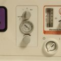
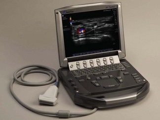
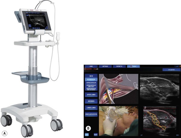
Over the past decade a large number of portable machines have become available. The very first machines had limited functionality and produced what is by comparison now such a poor image that one is tempted to wonder why practitioners and developers persisted with the technology. However, there are now any number of very good-quality portable or ‘laptop’ style machines available (manufacturers include SonoSite, Esaote and GE Healthcare). The machines may have Doppler, tissue harmonics and multibeam technology as standard, making them true alternatives to the traditional cart-based machines typically seen in radiology departments (Fig. 13.1).
Device specifics
Chapter 31 of this book is dedicated to the physics and technology of ultrasound imaging. The reader is encouraged to read the aforementioned chapter for further details of topics raised in this section on RA, which is concerned more with the application of ultrasound in RA and the small portable machines used for that purpose.
Most ultrasound machines have the following components in common:
• a signal generator producing an applied voltage (typically up to 100 volts) in brief bursts
• a piezoelectric transducer which converts electrical energy to acoustic pulses and vice versa
• a signal receiver which detects, amplifies and compresses signals returning to the transducer
• signal processing software for displaying the data in different modes
• a display together with the interface for controlling the machine
• a memory which stores still and video images and has connectivity ports for the output of images and other data.
Imaging modes used in ultrasound-guided regional anaesthesia
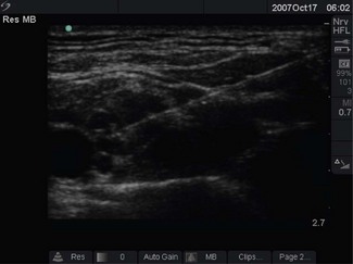
Modern scanners display ultrasound data in various forms. At present, brightness or B-mode is most commonly used for nerve imaging, producing a single two-dimensional image (hence also called 2D mode) from a slice of approximately 2 mm thickness and adjustable depth (Fig. 13.2).
These and other imaging modes, together with some further developments in image processing, are discussed more fully in Chapter 31. Software-driven post processing of the image is also now available to enhance needle visualization on some machines.
Controls
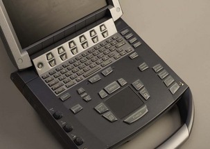
On the ultrasound machine, the most important controls that are required to generate and optimize the image are those for frequency, depth adjustment and focal zone, time gain compensation (TGC) and imaging mode selection (2D, C-mode, etc.) (Fig. 13.3).
Frequency adjustment facilities (presented sometimes as a choice of penetration, general and resolution modes) can be integrated into the system if using broadband transducers or it may require a change in transducer (probe) depending on the type of system in use.
Transducers
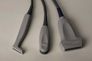
Transducer characteristics, such as operating frequency and probe shape, determine the image generated. The transducer frequencies used for peripheral nerve blocks range from 3 to 15 MHz. Modern transducers are broad bandwidth (broadband) transducers that are designed to generate more than one frequency. For example, a SonoSite HFL38 6–13 MHz transducer can generate ultrasound ranging in frequency from 6–13 MHz and is a 38 mm sized linear probe. With broad bandwidth transducers, the operator selects the examination frequency to match the target requirement. Linear and curvilinear (curved) transducers are most useful for nerve imaging to provide high-resolution images. Linear arrays produce images with a finely sampled, rectangular field of view, whereas curved arrays produce a diverging sector-shaped field of view that expands beyond the lateral extent of the transducer (Fig. 13.4).
The probe used should match the procedure being performed (Table 13.1). Choosing the wrong probe can make identification of anatomy difficult. It is important to use the highest frequency probe available for the depth of the target being scanned.
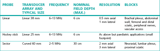
Probes have different size footprints; small linear probes (3.8 cm footprint) are available which are more dextrous in paediatric practice compared to the standard sized adult probe of 5–6 cm.
Features
Image processing software
Additional image processing software is available and desirable to achieve better image quality, e.g. speckle reduction imaging and tissue harmonic imaging. Speckle is a very characteristic texture commonly seen in ultrasound images. It is an interference pattern superimposed on the ‘true’ image by scatterers too small and closely spaced to be resolved (see Chapter 31 for further description). The pattern depends on the beam angle and can be suppressed by combining images acquired with multiple steered ultrasound beams (spatial compounding, labelled variously on machines as compound mode, CT or multibeam). Multibeam and tissue harmonic imaging can offer some advantages over conventional (pulse-echo) imaging, including improved contrast resolution, reduced noise and clutter, improved lateral resolution, reduced slice thickness, reduced artefact and, improved signal-to-noise ratio. They are none the less user selectable modes reflecting the fact that they do also have downsides and do not always enhance the image obtained. Manufacturers have proprietary algorithms driving such features which in combination with the processing power of the device may determine the efficacy in any particular application of these imaging modes.
On screen tutorials
User instructions presented as on-screen ‘help’ is an established feature in domestic consumer electronics and is increasingly prevalent in complex medical devices. Pattern recognition is an integral part of the use of ultrasound imaging to guide regional anaesthesia. In the Esaote MyLab One (Fig. 13.5A) the concept of on-screen help is further developed to include a library of images and explanatory notes: effectively a handbook of ultrasound guided regional anaesthesia, which can be shown alongside the real-time image to assist in the recognition of anatomy and the performance of blocks (Fig. 13.5B).
Needle visibility
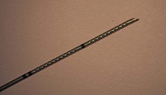
The ultrasound visibility of different needles has been investigated;3 however, no studies have investigated success rates with different needle types, so there is as yet no ‘ideal needle’, or any evidence that this will improve success rates or safety. There are, however, continuing developments of new needles aimed at facilitating block performance and needle visibility. Various surface coatings have been attempted to improve needle visibility, with little success. Piezoelectric vibrating needles is one example of an interesting new approach, but it has not gained currency.4 A more promising recent development is the SonoPlex needle (Pajunk, Geisingen, Germany), where a pattern deeply impressed into the surface of the needle shaft ensures that a strong reflective surface remains relatively perpendicular to the ultrasound beam at all needle angles (Fig. 13.6). Even more recently software-driven image enhancements (e.g. the ‘enhanced needle visualization’ software upgrade from Sonosite) can be used to allow better visualization of standard needles even when inserted in a steeper plane.
Introduction of ultrasound imaging into clinical practice
The successful use of ultrasound is highly operator dependent and as such has a distinct learning curve. Practitioners using ultrasound without training have been shown to have more complications and lower success rates. Guidelines for ultrasound-guided regional anaesthesia have recently been published.5,6 However, a universal agreement on how to teach ultrasonography for regional blocks is still lacking. A combination of basic and advanced workshops, and ongoing supervised practice, seems a logical approach to the safe and effective performance of ultrasound-guided blocks.
Nerve stimulators
Nerve stimulators in general are discussed more fully in Chapter 17. A peripheral nerve stimulator (Fig. 13.7) allows localization of peripheral nerves without the need for direct contact between the needle and the target nerve to elicit paraesthesia. The technique was first described in 1912 and is still in common use, although in the developed world now somewhat relegated to second place in favour of ultrasound.
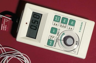
Characteristics of a nerve stimulator for localization of peripheral nerves include:7
1. adjustable constant current output from 0 to 5 mA. It should be easy for the operator or an assistant to adjust the delivered current
2. a short stimulation pulse. The shorter the stimulation pulse, the greater the ratio of the current required to stimulate when the needle tip is 1 cm away from the nerve compared to when the needle is immediately adjacent to the nerve. Most commercially available nerve stimulators produce monophasic square wave impulses of between 0.1 and 1.0 ms
3. clearly marked polarity. The needle should be connected to the cathode (−) and the anode (+) to the surface of the patient’s skin
Needles and catheters
General considerations
Some of these aspects are considered individually below.
Needle tip design
Traditional hypodermic needles have a cutting tip designed for easy penetration of skin and tissues and are best avoided for peripheral nerve blocks. In contrast a short bevelled needle is more ‘blunt’ in use and is believed to give improved ‘feel’ of anatomical layers aiding identification of tissue planes by eliciting a ‘pop’ as the layers are penetrated (compare Fig. 13.8 elements A, F, H). Theoretically, a short bevelled (or facetted) needle can touch a nerve eliciting paraesthesia with less risk of nerve injury,1 but there is some controversy. In general, it appears that long, flat bevels are more likely to cause nerve trauma,8 but that the trauma will be more serious if a short bevel needle does make vigorous contact with a nerve.9
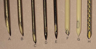
Pencil point needle tips (Fig. 13.8 elements C, D and G) are believed to separate tissues through which they pass rather than cutting them. It is not clear whether a short bevel or a pencil point tip is safer to use.
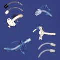
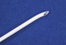
The Huber tip provides a blunt relatively non-cutting and side-facing advancing edge, which facilitates catheter placement and is hence commonly used on epidural needles and other needles for catheter-based peripheral nerve block techniques (Fig. 13.9).
Stimulating needles
The shaft of a stimulating needle is coated with an insulator (e.g. Teflon) so that any electrical current passed through the needle spreads into the tissues from the tip only (Fig. 13.8 elements F–H). This coating also decreases friction allowing easier advancement of the needle. They now always have an electrical lead attached for connection to a nerve stimulator (in the past needles were used with a crocodile clip onto the non-insulated needle shaft).
Catheters
Insertion
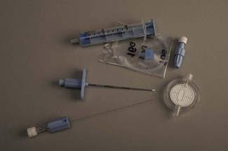
Catheters are used to facilitate continuous nerve blockade. The different catheter sets available contain an introducer, a catheter and associated parts such as a filter and detachable connector. A popular introducer design is the 18 G insulated stimulating needle with a curved Huber tip (Fig. 13.10). It is believed to ease the placement of the associated 21 G catheter, particularly if the nerve is to be approached at right angles to its long axis. Another introducer design is the plastic over the needle cannula (usually 15–17 G) familiar as the traditional intravascular cannula, which after removal of the introducing needle is used to convey the catheter. This type of introducer for catheter placement tends to be more troublesome and less popular as once the needle has been removed, the cannula is prone to misplacement and kinking during insertion and passage of the final catheter.
Design
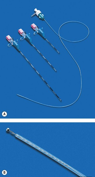
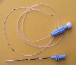
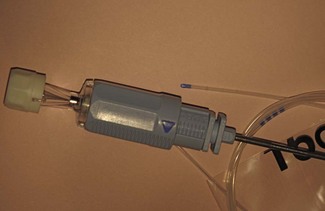
A stimulating catheter is made from insulating plastic material and usually contains a metallic wire, inside which the current is conducted to its exposed tip electrode (Fig. 13.11). Stimulating catheters are placed through a nerve block needle, which itself may be placed using nerve stimulation. The catheter can then be stimulated to reconfirm the catheter tip position in close proximity to the target nerve.
Needle diameter and length
Needle diameters are usually quoted in terms of standard wire gauge – usually shortened to gauge and represented as G. Table 13.2 shows the metric equivalents of some of the commonly used sizes. Standard notation is that the size is defined by the external diameter of the needle shaft, there being little or no standardization of internal diameters.

The diameter of needle required for a particular purpose will depend on two main factors:
• The viscosity of fluid that is to be injected. Local anaesthetics are usually prepared in aqueous solutions, which will pass through small diameter needles, but needles which are very small will significantly limit the speed at which other fluids (e.g. CSF or blood) can be aspirated. The latter is required for confirmation of correct placement or for the early recognition of a potential complication. Oil-based agents (for neurolytic blocks) will only pass easily through the larger diameter needles (at least 18 G).
• The rigidity required for its insertion. The longer the needle the more flexible it becomes, making it more prone to deflection, bending, buckling or even breakage. Thus, epidural needles are usually of 16 G or 18 G size to minimize these risks. Spinal needles need to be even longer, but large diameter needles make post-dural puncture headache (PDPH) more likely and so finer needles are used and inserted through an introducer.
Spinal anaesthesia
The Quincke spinal needle has a cutting tip (similar to a hypodermic needle: compare Fig. 13.8 elements A–C). 27 G Quincke needles have an incidence of 2.5–3.5% of PDPH. It is often opined that to insert these such that the bevel is parallel to the largely longitudinal dural fibres, produces a smaller defect in the dura as less fibres are transected by the cutting edge of the needle.
‘Atraumatic’ pencil point spinal needles like the Whitacre needle have a completely rounded non-cutting bevel with a solid tip, the opening being 2 mm proximal to the tip on the side. An adaptation of the Whitacre needle design is the Sprotte needle with a blunt ogival (bullet shaped) tip with an elongated lateral needle opening and a wider internal diameter for CSF flow (Fig. 13.8, elements D, E). These needle designs aim to push or stretch the dural fibres aside rather than cutting them, resulting in better dural closure after removal of the needle. They are associated with a significantly lower incidence of PDPH (0.8–1%).
Microspinal catheters
Various designs of needle and catheter system are available ranging from 20 G catheter through 18 G Tuohy needle, through to a 24 G catheter placed over a 29 G Quincke spinal needle which is then withdrawn on the end of a flexible stylet. Fig. 13.12 shows a typical 25 G microcatheter through 21G Sprotte needle system. Catheters as fine as 28–32 G are available.
The utility of microcatheter systems is limited by the difficulties in ensuring that such a fine catheter is correctly placed. Combined spinal/epidural techniques provide many of the benefits without the same concerns regarding catheter position, leaving spinal catheter systems to a select, but loyal following. In the past, a small number of patients have developed the cauda equina syndrome following continuous spinal anaesthesia. Although initially ascribed to the use of the indwelling microspinal catheters themselves, it now seems likely that the true cause was the repeated localized exposure of nerve roots to very high concentrations of hyperbaric 5% lidocaine.10
Epidural anaesthesia
Epidural access is most commonly performed using the Tuohy needle with a Huber tip to facilitate insertion of the epidural catheter (Fig. 13.13). The Huber tip is relatively blunt and the shape ensures that the catheter emerges at an angle of 20° to the shaft. The disadvantage is that a catheter that has been passed beyond this needle tip cannot be withdrawn without the risk of being sheared off.
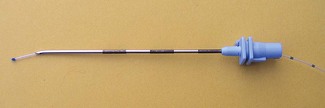
Figure 13.13 A Tuohy needle with a Huber tip and an epidural catheter emerging at an angle of 20° to the shaft.
The Crawford epidural needle, with a short conventional bevel, is sometimes used for a paramedian approach, as it slides off the lamina easily and a catheter can thread directly upwards when a 45–60° angle is used to enter the epidural space.
Most needles have 1 cm markings on the shaft to show the depth of insertion from the skin surface (Fig. 13.14). A 19 G needle of 5 cm length for paediatric use has 0.5 cm surface markings. All epidural needles are supplied with close fitting stylets to prevent tissue entering the lumen on insertion. Catheters for epidural placement are offered with a choice of single end hole or multiple side holes, have appropriate centimetre markings and, once in place, are attached to a 0.2 µm mesh hydrophilic filter through which the anaesthetic agent is injected.
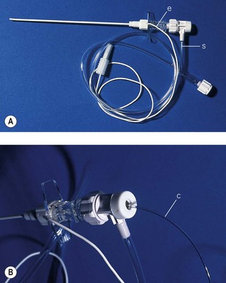
Equipment for combined spinal/epidural (CSE) techniques
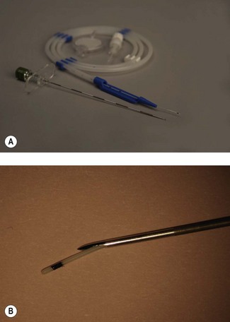
With the NTN, the intrathecal injection follows epidural insertion of the Tuohy needle, which then serves as an introducer for the very fine (25–27 G) intrathecal needle. After the spinal needle is removed the epidural catheter is inserted through the Tuohy needle. Usually, a pencil point type spinal needle of sufficient length (120 mm) to allow 13–15 mm projection beyond the end of a standard Tuohy needle is used (Fig. 13.15). Although sufficient projection is important longer spinal needles can puncture the anterior aspect of the dura and cause a greater CSF leak.
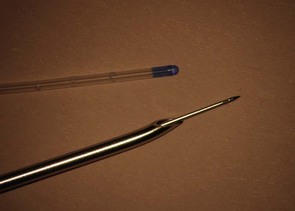
Figure 13.15 27 G pencil point needle exiting a 16 G Tuohy needle, and the associated epidural catheter for comparison.
Commercially available kits have been produced for CSE to overcome various concerns (Fig. 13.16). Using matched needles to avoid damage to the spinal needle as it is passed through the Tuohy epidural needle prevents introduction of very fine metal particles into the CSF. Minimal drag between the two needles is essential to generate the dural ‘click’ when the spinal needle punctures the dura.
A conventional spinal needle, which does not lock within the much larger epidural needle, is minimally held by the dura alone and is difficult to handle and stabilize during injection of spinal medication. The displacement of the spinal needle during aspiration of the CSF and injection may result in failed anaesthesia or may push the spinal needle deeper, leading to nerve damage or anterior dural perforation. Several adjustable locking devices have been developed, but some designs can interfere with the essentially tactile task of identifying dural puncture. Fig. 13.17 shows the collar of Portex CSEcure system which permits easy needle advancement, but can lock it 0.5 mm intervals whilst still allowing the spinal needle to be rotated.
Ambulatory continuous infusions of local anaesthetic
Elastomeric infusion pumps are discussed in Chapter 19. The devices used for ambulatory regional analgesia, patient-controlled analgesia and wound irrigation are fundamentally the same.
Non-luer connectors
At the time of writing it is not known what shape the connecting hub of needles, syringes and other devices designed for regional anaesthesia and centrineural access in the UK will take ultimately; though this may have been settled by the time this edition is published. The National Patient Safety Agency of the UK in November 2009 issued an alert requiring all UK hospitals to introduce syringes and needles with specific connections aiming to prevent ‘wrong route’ errors. A staged deadline of April 2011 and 2013 aims to have equipment designed for injection around major nerves to be incompatible with needles and syringes for vascular and other usage11. At present there are as yet no ‘non-Luer’ systems available for purchase nor any contenders that have been widely evaluated in use. It appears that there will be a heterogeneity of designs adopted by various manufacturers, likely ultimately resulting in a confusion of incompatible needles and syringes for the end user. (see also Chapter 19, Infusion lines).
1 La Grange P, Foster PA, Pretorius LK. Application of the Doppler ultrasound blood flow detector in supraclavicular brachial plexus block. Br J Anaesth. 1978;50:965–967.
2 Kapral S, Krafft P, EibenbergerK, Fitzgerald R, Gosch M, Weinstabl C. Ultrasound-guided supraclavicular approach for regional anaesthesia of the brachial plexus. Anesth Analg. 1994;78:507–513.
3 Maecken T, Zenz M, Grau T. Ultrasound characteristics of needles for regional anesthesia. Reg Anesth Pain Med. 2007;32:440–447.
4 Klein SM, Fronheiser MP, Reach J, Nielsen KC, Smith SW. Piezoelectric vibrating needle and catheter for enhancing ultrasound-guided peripheral nerve blocks. Anesth Analg. 2007;105:1858–1860.
5 Board of the Faculty of Clinical Radiology, Royal College of Radiologists. Ultrasound training recommendations for medical and surgical specialties. London: Royal College of Radiologists; 2004.
6 Sites BD, Chan VW, Neal J, Weller R, Grau T, Koscielniak-Nielsen ZJ, et al. The American Society of Regional Anesthesia and Pain Medicine and the European Society of Regional Anaesthesia and Pain Therapy. Joint Committee recommendations for education and training in ultrasound-guided regional anesthesia. Reg Anesth Pain Med. 2009;34:40–46.
7 Kaiser H, Niesel HC, Hans V. Fundamentals and requirements of peripheral electric nerve stimulation. A contribution to the improvement of safety standards in regional anesthesia. Reg Anesth. 1990;13:143–147.
8 Selander D, Dhuner KG, Lundborg G. Peripheral nerve injury due to injection needles used for regional anesthesia. Acta Anaesthsiol Scand. 1977;21:182.
9 Rice ASM, McMahon SB. Peripheral nerve injury caused by injection needles used in regional anaesthesia: influence of bevel configuration, studied in a rat model. Br J Anaesth. 1992;69:433.
10 Faccenda KA, Finucane BT. Complications of regional anaesthesia Incidence and prevention. Drug Safety: An International Journal of Medical Toxicology and Drug Experience. 2001;24(6):413–442.
11 National Patient Safety Agency. Safer spinal (intrathecal) epidural and regional devices – Part A. http://www.nrls.npsa.nhs.uk/alerts/?entryid45=94529&q=0%C2%ACwrong+route%C2%ACaccessed28/7/11, 24 November 2009. NPSA/2009/PSA004A (and updated 31 January 2011: available at