Chapter 27 Epicardial Ventricular Tachycardia
Electrophysiological Substrate
In patients with nonischemic CMP, detailed epicardial electroanatomical substrate mapping has identified large confluent low-voltage areas consistent with myocardial scar. The epicardial scar areas are typically larger than the endocardial left ventricular (LV) scar areas and have a typical distribution similar to that for endocardial LV scars, usually located in basal lateral areas of the LV adjacent to the mitral valve annulus. Epicardial ablation is needed more often in patients with sustained monomorphic VT associated with dilated, nonischemic CMP than in patients with prior MI.1
In patients with ARVD, sizable low-voltage areas often involve the infundibulum, free wall, and basal perivalvular regions, constituting the endocardial substrate. More recently, extensive epicardial low-voltage areas, often with fractionated and late electrographic recordings, have been identified. The epicardial scar is consistently larger than that on the endocardial surface. In patients with ARVD and VT refractory to endocardial ablation, the origin of VT defined on the epicardium is frequently noted beyond the endocardial-defined scar.2 In a recent report, the highest prevalence of epicardial VTs was observed in patients with ARVD (41%) and nonischemic CMP (35%), followed by patients with ischemic heart disease (16%).3
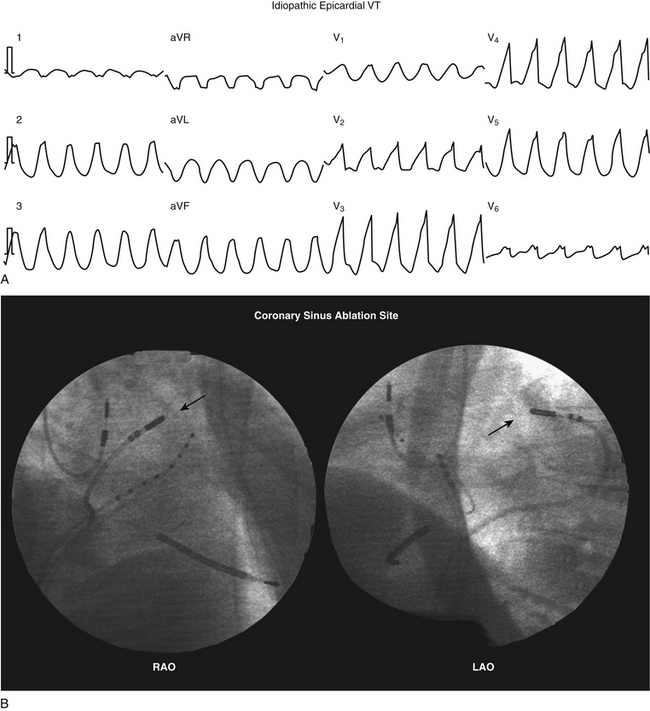
Small series have also reported successful ablation of epicardial VTs following a failed endocardial ablation in patients with idiopathic outflow tract VTs. Often underrecognized, the incidence of an epicardial origin in idiopathic VT may be as high as 14%. Idiopathic outflow tract VTs with epicardial origins can originate close to the anterior interventricular vein, great cardiac vein, and middle cardiac vein; and successful ablation from within these structures has been reported. When this approach fails, percutaneous epicardial mapping and ablation have been reported to be feasible and successful.4
Electrocardiographic Features
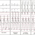
Several ECG findings can suggest an epicardial origin of the VT with right bundle branch block (RBBB)–like configuration, all of which generally rely on the late engagement of His-Purkinje fibers by exits on the epicardium, resulting in intramyocardial delay of conduction and a slurred initial part of the QRS complex: (1) pseudo-delta wave (so called because of its similarity to the slurred upstroke delta wave observed during ventricular preexcitation) greater than 34 milliseconds (measured from the earliest ventricular activation to the earliest fast deflection in any precordial lead) has a sensitivity of 83% and a specificity of 95%; (2) long R-wave peak time in lead V2 (i.e., interval from the beginning of the QRS complex to the time of initial downstroke of the R wave after it has peaked [previously known as the intrinsicoid deflection]) greater than 85 milliseconds has a sensitivity of 87% and a specificity of 90%; (3) shortest RS complex duration (measured from the earliest ventricular activation to the nadir of the first S wave in any precordial lead) equal to or greater than 121 milliseconds has a sensitivity of 76% and a specificity of 85%; and (4) QRS duration greater than 200 milliseconds (see Fig. 22-8).4,5
These criteria, however, do not seem to apply uniformly to all LV regions or to VTs originating from the right ventricle (RV). Other site-specific criteria have been suggested for identifying an epicardial origin for LV VTs: (1) the presence of a Q wave in lead I for basal superior and apical superior VTs; (2) the absence of a Q wave in any of the inferior leads for basal superior VTs; and (3) the presence of a Q wave in the inferior leads for basal inferior and apical inferior VTs. Also, measurement of the maximal deflection index (defined as the time from QRS onset to maximal deflection in precordial leads divided by the QRS duration) can help identify epicardial VT originating in the LV outflow region. A delayed shortest precordial maximal deflection index (≥0.55) identifies epicardial VT remote from the aortic sinus of Valsalva with high sensitivity and specificity. This observation is consistent with slower spread of activation from a focus on the epicardial surface relative to the endocardium and delayed global ventricular activation resulting from later engagement of the His-Purkinje network.6,7
Epicardial VTs originating close to the proximal segment of the great cardiac vein typically display RBBB morphology, whereas VTs originating close to the distal segment have left bundle branch block (LBBB) morphology. This may be explained by a location within the basal-lateral myocardium for the former and a more anterobasal location for the latter arrhythmias. If the site of origin is in the proximal segment of the great cardiac vein, the initial vector is directed toward lead V1, accounting for the RBBB morphology. As the site of origin moves toward the distal part of the great cardiac vein, closer to the anteroseptal myocardium, the initial vector is directed away from V1, resulting in LBBB morphology. An R-wave width greater than 75 milliseconds in lead V1 is useful for differentiating epicardial idiopathic VTs from endocardial arrhythmias. The broader R wave is explained by a more posterior position relative to lead V1 compared with the RV outflow tract (RVOT). However, because of a more anterior position relative to lead V1, the epicardial arrhythmias that are located within the distal part of the great cardiac vein have a narrow R wave in lead V1, making them impossible to distinguish from RVOT VT.7,8 Epicardial VTs that appear to follow the anterior interventricular vein often have a characteristic loss of R wave from leads V1 and V2 with broad R waves in leads V3 through V6.
Although various ECG characteristics have been used to predict whether an epicardial approach may be required based on the VT morphology, it is important to understand that the QRS morphology is related solely to the VT exit site and this does not imply that some other component of the circuit (such as the critical isthmus or entrance site) cannot be ablated from the endocardium, even when an epicardial exit is implied by the ECG characteristics. Therefore, it is unlikely that the surface ECG by itself will ever be entirely predictive of the need for epicardial access for mapping and ablation for any given VT.5 Additionally, large areas of conduction delay often present in patients with myocardial scar can produce misleading activation sequences and confound ECG prediction.9
Percutaneous Epicardial Approach
Clinical Considerations
VT originating from the subepicardium is an important cause of failure of endocardial ablation approaches. Mapping arrhythmia foci or circuits that are deep within the myocardium or in the epicardium can be attempted via the coronary sinus (CS) or pericardial space. The CS approach, however, has important limitations. Catheter manipulation is limited by the anatomical distribution of the cardiac veins, and epicardial circuits may be identified only when the vessel cannulated happens to be in the region of the circuit. An alternative epicardial approach involves inserting an introducer sheath percutaneously into the pericardial space in the manner used for pericardiocentesis. The subxiphoid approach to the epicardial space allows extensive and unrestricted mapping of the epicardial surface of both ventricles, and has been used most commonly for VT mapping and ablation (far less so for supraventricular arrhythmias). Nonetheless, mapping of the CS and accessible coronary venous branches can be performed prior to the percutaneous epicardial approach to look for clues of an epicardial origin of the VT circuit, and has been particularly useful in idiopathic outflow tract VTs.4,9
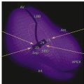
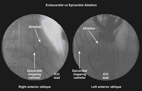
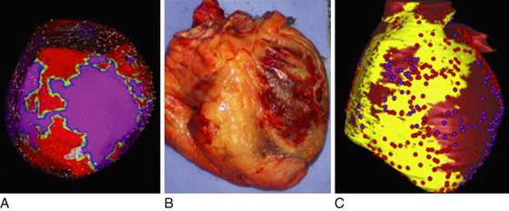
Catheter ablation from the epicardium is often required for elimination of VTs due to nonischemic CMP and is occasionally useful for VTs in a variety of other diseases, as well as some idiopathic VTs. Nonetheless, despite the increasing recognition that ventricular arrhythmias may originate from epicardial foci, epicardial VT ablation remains a specialized procedure and is performed at relatively few centers. In the majority of reported cases, percutaneous epicardial VT ablation has been performed only after failure of a thorough endocardial mapping and ablation session, at a separate setting or during the same setting after exhausting endocardial mapping efforts. Simultaneous endocardial and epicardial mapping can have several advantages (Fig. 27-1), such as a better chance to map and ablate all inducible VTs, reduce the number of procedures required for patients with suspected epicardial VTs, and an opportunity to acquire more expertise with the technique.4 Also, epicardial mapping and ablation may be useful as a first procedure when endocardial mapping is not an option because of intraventricular thrombi or in patients with metallic prostheses in the aortic and mitral valves.4
There are several conditions that can significantly limit the feasibility of percutaneous epicardial mapping and ablation. Previous cardiac surgery usually results in significant pericardial fibrosis, and the pericardial space is often, but not always, virtually replaced by fibrotic adhesions. In this setting, percutaneous cannulation of the pericardial sac is very difficult; even when percutaneous cannulation is successful, manipulation of the instruments is extremely limited and difficult. Additionally, pericardial venous varices have been reported in patients with SVC and azygous venous occlusion. Thus, catheter manipulation and ablation inside the pericardial space of a patient with pericardial varices can result in severe bleeding complications. When pericardial varices are suspected, the diagnosis can be made by three-dimensional (3-D) computed tomography (CT) angiography. Also, the presence of a large hiatal hernia can predispose to inadvertent perforation (and subsequent mediastinal infections) during cannulation attempts. Congenital absence of the pericardium is a rare congenital anomaly (approximately 1 in every 10,000 autopsies) that is most often asymptomatic and can be an incidental finding after the patient is referred for a pericardial procedure. In the preprocedural evaluation, this rare anomaly may be suspected by an abnormal cardiac rotation or silhouette on the chest x-ray film. Definitive diagnosis can be made by CT or magnetic resonance (MR) imaging.10
Preablation Evaluation
Careful analysis of the ECG during VT or premature ventricle complexes (PVCs) is essential. As noted, different ECG criteria for recognizing an epicardial origin of arrhythmia have been proposed. Additionally, MR imaging can help identify epicardial substrate in cardiomyopathies.3 Furthermore, evaluation should include comprehensive clinical assessment and imaging studies to recognize any preexisting contraindications, and to minimize complications. Chest radiograph, echocardiography, and cardiac CT or MR imaging have proven to be useful for screening these patients.
Contrast-Enhanced Magnetic Resonance Imaging
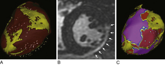
Delayed contrast-enhanced MR imaging delineates regions of scar tissue potentially forming part of the arrhythmia substrate in patients with ischemic and nonischemic CMP, and enables the depiction of transmural and nontransmural scars with high spatial resolution, allowing determination of whether the scar is endocardial, intramyocardial, or epicardial (Fig. 27-2).
The suspicion of an epicardial VT substrate can facilitate planning of VT ablations, such as for a combined endocardial and epicardial approach, especially given the fact that visualization of epicardial or intramyocardial scar on preprocedure delayed enhancement MR imaging was found to be predictive of failure of the endocardial approach and of the need for the epicardial approach for VT ablation.11
Cardiac MR imaging can also help determine the underlying etiology of nonischemic CMP in some patients, such as myocarditis, sarcoidosis, and ARVD, which can be associated with a higher susceptibility for VT. Furthermore, in patients undergoing epicardial mapping and ablation procedures, registration of preacquired MR images with real-time electroanatomical mapping allows visualization of ventricular anatomy and obstacles to procedural success, such as epicardial fat, which can be helpful during the mapping procedure in differentiating the cause of low epicardial voltages (fat versus scar).11
Contrast-Enhanced Computed Tomography
A contrast-enhanced CT scan enables detailed and comprehensive evaluation of LV myocardium using triple, multimodality imaging based on anatomical, dynamic, and perfusion parameters to identify abnormal substrate (myocardial scar and border zone) with high spatial (≤1 mm) and temporal resolution, which can be derived from a single CT scan. Areas of CT hypoperfusion correlate best with areas of abnormal voltage (<1.5 mV) rather than scar alone (<0.5 mV). Perfusion imaging from CT enables characterization of the transmural extent and intramyocardial location of scar tissue and visualization of surviving mid- and epicardial myocardium in the regions of scar, which can help identify areas potentially involved in the VT substrate. Such preprocedural information can help the operator plan an appropriate mapping and ablation strategy and better inform the patient about the risks, benefits, and chances of procedural success.12
The 3-D CT-defined abnormal myocardium can be accurately extracted and embedded in clinical mapping systems displaying areas of abnormal anatomical, dynamic, and perfusion parameters for substrate-guided VT ablations.12 Additionally, CT epicardial fat imaging can be used to characterize the extent of fat tissue by extracting and integrating epicardial fat information into the 3-D electroanatomical voltage map, thereby helping to distinguish epicardial fat from scar tissue.13
Anatomical Considerations
The pericardium is a double-walled, flask-shaped sac that contains the heart and the roots of the great vessels, superior vena cava (SVC), and pulmonary veins (PVs). By separating the heart from its surroundings—the descending aorta, lungs, diaphragm, esophagus, trachea, and tracheobronchial lymph nodes—the pericardial space allows complete freedom of cardiac motion within this sac.10
The pericardium consists of two sacs intimately connected with one another: an outer fibrous envelope (the fibrous pericardium) and an inner serous sac (the serous pericardium). The fibrous pericardium consists of fibrous tissue and forms a flask-shaped bag, the neck of which is closed by its fusion with the external coats of the great vessels, while its base is attached by loose fibroareolar tissue to the central tendon and to the muscular fibers of the left side of the diaphragm. The fibrous pericardium is also attached to the posterior sternal surface by superior and inferior sternopericardial ligaments.10 These attachments are essential to maintain the normal cardiac position in relation to the surrounding structures, to restrict the volume of the thin-walled cardiac chambers (right atrium and ventricle), and also to serve as direct protection against injuries.
The serous pericardium is a delicate membrane that lies within the fibrous pericardium and lines its walls; it is composed of two layers: the parietal pericardium and the visceral pericardium. The parietal pericardium is fused to and inseparable from the fibrous pericardium. On the other hand, the visceral pericardium, which is composed of a single layer of mesothelial cells, is part of the epicardium (i.e., the layer immediately outside of the myocardium) and covers the heart and the great vessels except for a small area on the posterior wall of the atria. The visceral layer extends to the beginning of the great vessels, and is reflected from the heart onto the parietal layer of the serous pericardium along the great vessels in tubelike extensions. This happens at two areas: where the aorta and pulmonary trunk leave the heart and where the SVC, IVC, and PVs enter the heart.10 The serous pericardium is also metabolically active.
At the pericardial reflections and at the posterior wall between the great vessels, the pericardial space is divided up into a contiguous network of recesses and sinuses. There are three sinuses in the pericardial space: the superior sinus, the transverse sinus, and the oblique sinus. The superior sinus (superior aortic recess) lies anterior to the upper ascending aorta and main pulmonary artery. The transverse sinus is limited by a pericardial reflection between the superior PVs and contains the right pulmonary artery. The oblique sinus is confined by the pericardial reflections around the PVs and the IVC. The postcaval recess lies behind the SVC, the right pulmonary artery, and the right superior PV. The right and left PV recesses extend between their respective superior and inferior PVs.10
The pericardial cavity or sac is a continuous virtual space that lies between the parietal and visceral layers of serous pericardium. The heart invaginates the wall of the serous sac from above and behind, and practically obliterates its cavity, the space being merely a potential one. The sac normally contains 20 to 40 mL of clear fluid that occupies the virtual space between the two layers. Because all pericardial reflections are located basally in relation to the great vessels, the entire epicardial surface is accessible from the pericardial space, except for the atrial and ventricular septa, which are not in direct contact with the pericardium. Unlike the endovascular approach, the pericardial space is notable for the absence of obstacles and the relative ease with which catheter manipulation can be performed.10 By the same token, achieving firm, stable contact with the catheter tip at the target site may be difficult.
Technical Considerations
The subxiphoid approach procedure may be performed under conscious sedation, deep sedation with the support of an anesthesiologist, or general anesthesia. Deep sedation or general anesthesia allows better control of respiratory motion, which can potentially reduce the chance of unintentional RV puncture, as well as better pain control, given the fact that epicardial radiofrequency (RF) ablation is usually associated with significant pain and patient discomfort. On the other hand, if patients are paralyzed under general anesthesia, diaphragmatic motion with phrenic nerve stimulation during pacing may not occur to warn of proximity of RF applications.4 Intravenous antibiotics should be routinely administered within an hour prior to the procedure. Previous heparin administration should be reversed before pericardial access; this is accomplished by protamine infusion to decrease the activated clotting time to less than 150 seconds.
Initially, catheters are positioned in the CS and RV apex through the femoral approach. The pericardial space is accessed using a 17- or 19-gauge Tuohy needle (Codman Inc., Raynham, Mass.), which is also used to enter the epidural space when administering epidural anesthesia (typically approximately 100 mm in overall length and a 1.5-mm outer diameter). The puncture is performed at the angle between the left border of the subxiphoid process and the lower left rib, with the needle pointing to the left shoulder. The puncture needle approaches the site with a shallow angle in order to penetrate the skin and slide under the rib cage. After crossing the subcutaneous tissue, the stylet is removed, and a 10-mL syringe containing 1% lidocaine or a nonionic contrast agent is attached to the proximal port of the needle. The needle is then advanced under fluoroscopic guidance (40-degree left anterior oblique [LAO] view or, preferably, biplane right anterior oblique [RAO] and LAO projections) until close to the cardiac silhouette. The needle angle is adjusted according to the region that the operator wishes to access. Directing the needle superiorly at a relatively shallow angle, aiming for the RV apex in the RAO projection, generally allows entry into the pericardial space anteriorly over the RV and facilitates access to the anterior aspect of the RV and LV. Directing the needle more posteriorly and toward the left shoulder allows it to enter the pericardium over the diaphragmatic portion of the heart, such that the sheath typically tracks along the posterior aspect of the LV, as observed in the LAO projection. The medial third of the RV is the preferred entry region because of the absence of major coronary vessels in this region.9,14
In the 40-degree LAO view, injection of a small amount of contrast (approximately 1 mL) can help assess the relation of the needle to the parietal pericardium (Video 21  ). If the diaphragm has not been reached, the contrast will be seen in the subdiaphragmatic area. Once tenting of the pericardium is seen, a slight advance achieves entry into the space, and often one can feel the “pop” as the needle penetrates the fibrotic parietal pericardial wall. Contact of needle with the myocardium can be suggested by tactile feedback, occurrence of ventricular ectopy, or observation of a current of injury from a crocodile clip attached to the shaft of the needle. In this setting, further advancement of the needle can result in ventricular puncture and should be avoided.15
When the needle reaches the pericardial sac, aspiration without blood indicates that the needle has not entered the RV, and injected contrast will spread around the heart, restricted to its silhouette. In some cases, the needle will get close enough to the heart, but the contrast will not be clearly identified in the pericardial sac. In this situation, despite the needle being out of the pericardial sac, it is likely that a defect has been created in the membrane, through which it is possible to advance a soft-tipped guidewire and enter the pericardial sac. If the needle is not close enough to the pericardial membrane, the guidewire will move toward the subdiaphragmatic area. In these cases, the wire must be pulled back and small movements with the needle and the wire must be performed until the pericardial space is reached.9
Confirmation that the wire is intrapericardial and has not been inadvertently inserted into a cardiac chamber is obtained by observing the course of the wire in multiple fluoroscopic projections confirming that it crosses multiple cardiac chambers, hugging the edge of the cardiac silhouette in the 40-degree LAO view, circumferential to both the right and left heart, and without induction of PVCs. Observation in the RAO or anterior-posterior projection alone can be misleading, as a wire that enters the RV and passes into the right atrium (RA) or pulmonary artery can be misinterpreted as intrapericardial.9,15
Inadvertent RV puncture is not rare, but is usually benign if only the needle or wire has entered the chamber in a patient who is not anticoagulated. When the RV is inadvertently entered with the needle (indicated by aspiration of blood or contrast injection passing to the pulmonary artery), the needle can be withdrawn slightly (reentering the pericardial space after exiting the ventricle); contrast injection can then show silhouetting of the heart, and at that point the guidewire is advanced into the pericardial space. The small hole in the RV generally seals without incident. If the dilator and sheath have been passed into the RV, the larger hole may require surgical repair.4
Attempted epicardial access fails in approximately 10% of patients. The percutaneous approach to the pericardial space can be difficult in patients with pericardial adhesions (e.g., following cardiac surgery or pericarditis). In postsurgical patients, the adhesions are mostly concentrated in the anterior portion of the heart; therefore, the puncture must be directed toward the diaphragmatic area. In contrast, adhesion can be more diffuse in postpericarditis patients. Surgical creation of a subxiphoid pericardial window and manual dissection and lysis of the lesions to allow catheter mapping and ablation in the EP laboratory have been shown to be feasible in a small series.4
 ). If it is necessary to insert another catheter, a second guidewire can be advanced through the sheath, which should be removed, leaving two wires inside the pericardial space. Subsequently, a separate sheath is introduced over each of the guidewires. Alternatively, a second puncture of the pericardial sac may be performed, using the same steps described for the first puncture. Before removing the dilator out of the sheath, the sheath must be pushed against the chest to ensure that the tip of the sheath is placed inside the pericardial sac. Although using a standard 15 cm, 8 Fr sheath may suffice for inferior wall VT circuits, the use of longer sheaths (e.g., Agilis; St. Jude Medical, St. Paul, Minn.) should be considered, especially in patients with a larger thoracic anteroposterior dimension.
There is concern that abrasion or laceration of pericardial structures can occur by the edges of a stiff sheath if the sheath is left in the pericardium without a catheter protruding from the lumen. Therefore, it is recommended not to leave a large sheath in the pericardial space without a catheter in place. Also, it is important to lead with a wire or ablation catheter before advancing or moving the curl of the sheath to avoid damaging epicardial structures.9
Before introducing the mapping-ablation catheter, the sheath must be aspirated to check for bleeding. Approximately 10% to 20% of patients experience pericardial bleeding, particularly if inadvertent RV puncture has occurred. Bleeding is managed by frequent aspiration from the pericardial access sheath. It is not uncommon to aspirate 10 to 30 mL of bloody drainage from the pericardial sheath early in the procedure. At this point, anticoagulation should not have been administered; therefore, any bleeding should be self-limited and is generally considered a minor complication because it is not necessary to interrupt the procedure. Major bleeding is rare, and it can be related to the learning curve. Systemic anticoagulation with intravenous heparin is started when subsequent LV endocardial mapping, coronary angiography, or both are desired only after verifying the absence of continued pericardial bleeding.9
Percutaneous Epicardial Mapping
The approach to epicardial mapping is essentially the same as for endocardial ablation, including activation mapping, entrainment mapping, substrate mapping, and pace mapping, discussed in detail in Chapter 22. The following discussion highlights certain peculiarities pertaining to the percutaneous epicardial approach to mapping.
Activation Mapping
In scar-related VTs, inability to identify the reentry circuit isthmus on the endocardium can suggest that the isthmus is epicardial or intramural. In these cases, endocardial activation mapping can demonstrate a focal point of earliest endocardial activation where entrainment mapping indicates a potential exit or outer loop site, but ablation fails to interrupt VT, suggesting that there is an epicardial or intramural circuit with a broad endocardial exit. Some idiopathic VTs that have a focal origin also have a point of earliest endocardial breakthrough, but typically activation is not presystolic.9
If an appropriate target site for VT ablation cannot be identified despite extensive endocardial and epicardial mapping, an epicardial VT circuit sheltered by epicardial fat or an intramural circuit should be suspected. Cardiac MR imaging can potentially help delineate the extent of epicardial fat as well as intramural scarring suggestive of an intramural circuit.13
Entrainment and Pace Mapping
Entrainment and pace mapping maneuvers are usually difficult to perform using bipolar pacing because of a very high epicardial stimulation threshold (>15 mA) in approximately 70% of cases, likely related to the presence of epicardial fat and/or poor catheter contact due to freedom of catheter movement in the pericardial space.4 With unipolar pacing, the pacing threshold generally is less than 10 mA at 2 milliseconds in normal tissue.9 Epicardial fat less than 5 mm in thickness interposed between the ablating catheter and the epicardium usually does not modify the epicardial ventricular stimulation threshold.14 Of note, ablation with irrigated RF generally renders the pacing threshold at the target area greater than 10 mA secondary, in part, to introduction of the irrigant fluid into the pericardial space.9 This fluid can potentially result in decreased physical contact between the electrode and epicardial surface.
Electroanatomical Substrate Mapping
Substrate and VT mapping approaches are similar to those described for the endocardium. Areas of infarction or scar have low-amplitude electrograms similar to findings during endocardial mapping. However, epicardial fat, which is concentrated along the coronary sulcus and the interventricular grooves, can cause low-amplitude electrograms, falsely suggesting scar in voltage maps. Normal epicardial electrograms demonstrate bipolar signal amplitude typically above 0.94 to 1.5 mV; whereas signal amplitude associated with fat, large vessel coronary anatomy, or both might demonstrate significantly lower amplitude.4,9,13,16
As noted, epicardial fat less than 0.8 to 5 mm in thickness interposed between the ablating catheter and the epicardium usually does not modify the amplitude or duration of the bipolar epicardial electrogram. However, in areas with a layer of epicardial fat greater than 5 mm in thickness the amplitude of the bipolar epicardial electrogram can decrease, resulting in ventricular noncapture, which may confound the ability to discriminate between fat and scar. Importantly, despite the lower electrogram amplitude, epicardial fat will not produce “abnormal” (fractionated and split) electrograms. Therefore, to avoid a misclassification of low-voltage areas due to epicardial fat or major coronary vasculature as abnormal, it is important to analyze the location and extent of the confluent voltage abnormality as well as the electrogram signal characteristics. The presence of abnormal electrograms (fractionated, split, or late potentials) is usually a more reliable indicator of scar.1,13,14
Registration of preacquired CT or MR images detailing the LV substrate with the real-time 3-D electroanatomical voltage map allows visualization of regions of scar tissue and can potentially facilitate mapping and ablation (see Fig. 27-2). CT and MR imaging can also be used to characterize the extent of fat tissue by extracting and integrating epicardial fat information into the electroanatomical voltage maps, thereby helping to distinguish epicardial fat from scar tissue and identify areas that are difficult to penetrate because of extensive epicardial fat (Fig. 27-3).13
Percutaneous Epicardial Ablation
Radiofrequency Ablation
The target for ablation is selected exactly like the endocardial target is selected. RF energy remains the primary ablative energy source for epicardial ablation. During standard RF energy application in the pericardial space, heating to the point of thrombus formation and charring is of less concern, because there is no potential for arterial embolization from the epicardial space; therefore, higher temperatures (>60°C) can be tolerated. However, standard RF ablation may not be as effective when delivered to the epicardium compared with lesions delivered to the endocardium because of the lack of convective cooling of the ablation electrode by the circulating blood. This results in high electrode temperatures at low-power settings (≤10 W), limiting power delivery in the pericardial space and impairing lesion formation. Additionally, the presence of epicardial fat (≥3.5 to 10 mm in thickness) between the ablation catheter and the targeted area can also represent an important obstacle to the effectiveness of VT ablation.4,9,13,14
On the other hand, open and closed loop irrigated catheters allow the delivery of energy at power settings capable of creating larger and deeper (up to 5 mm) epicardial lesions than standard RF ablation, even in the absence of circulating blood in the pericardial space. Additionally, the presence of epicardial fat interposed between the catheter tip and the myocardial tissue only moderately attenuates the efficacy of cooled-tip ablation.4
Optimal parameters for RF power titration and irrigation are not completely defined. With external irrigation, it is desirable to use lower flow rates, as compared with those used during endocardial mapping and ablation, to limit infusion of fluid into the pericardial space, because thrombus formation in the epicardium does not pose a risk of embolization. Commonly, the flow rate is set at 0 to 2 mL/min during mapping and at 10 to 20 mL/min during ablation, and is titrated as required to maintain electrode temperature at less than 50°C. RF energy is commonly delivered at a power output of 30 to 50 W for 60 to 120 seconds. Monitoring for an impedance fall is commonly used to assess likely adequate power delivery.9
With open irrigation, an obligatory fluid volume will enter the pericardial sac and, unless intermittently or continuously evacuated, it gradually results in cardiac tamponade. Therefore, intrapericardial fluid must be periodically drained after every few RF applications or every 15 to 20 minutes. This can be accomplished by intermittently removing the ablation catheter to allow aspiration from the pericardial sheath or placing a second pericardial catheter for drainage purposes. Alternatively, using a single sheath that is larger than the ablation catheter allows aspiration of fluid around the catheter from the side port, either intermittently or continuously (via attaching the side port to a suction bottle or gravity drain) without withdrawing the ablation catheter.4,9,17
Internally cooled RF ablation is an attractive choice for pericardial ablation as no fluid is infused and one need not worry about monitoring pericardial fluid throughout the ablation procedure.18
Prevention of Coronary Artery Injury
Coronary artery injury, severe spasm, or both can occur during epicardial mapping and RF ablation. The base and the anterior and posterior septal areas are the more dangerous zones. Prior to ablation, direct visualization of the relation between the ablation site and adjacent coronary arteries must be obtained, usually by coronary angiography performed with the ablation catheter on the target site. An absolute safe distance between the ablation site and epicardial artery has not been defined, and likely varies depending on the RF energy applied, coronary artery diameter and flow, and the presence of overlying fat. Based on available data and experience, a distance of at least 5 mm between the ablation electrode and an epicardial artery is commonly accepted. It is also important to ensure that the catheter is not touching the vessel at any point of the cardiac cycle during angiography. Coronary artery spasm has been reported during mapping in the pericardial space and could occur as a result of ablation close to the artery; extrinsic compression of a coronary artery can also result from edema caused by nearby ablation. Cryoablation appears to have less risk of coronary injury in animal models, but can still create occlusion and intimal damage when in close proximity, particularly to small vessels. Further confirmatory studies are warranted.4
Prevention of Phrenic Nerve Injury
The left phrenic nerve is potentially susceptible to injury along its epicardial course adjacent to the lateral LV wall. The left phrenic nerve descends behind the left brachiocephalic vein and passes over the aortic arch, pulmonary trunk, and then with the pericardium over the left atrial (LA) appendage. From there it descends along the pericardium over the LV and frequently passes laterally over the obtuse margin of the LV, close to the lateral vein and the left marginal artery and, in only a small percentage of cases, close to the left main coronary artery and great cardiac vein. Not infrequently, the phrenic nerve courses through sites that might be considered appropriate target ablation sites, potentially limiting the safety and efficacy of ablation.19
Catheter ablation should be avoided at sites adjacent to the phrenic nerve. Alternatively moving the nerve away from the myocardium by injection of air into the pericardium or placement of a balloon catheter between the ablation target site and nerve can allow safe RF ablation. Alternative energy sources such as cryoenergy have been used to prevent phrenic nerve injury. Cryomapping uses temporary phrenic nerve injury to determine when to avoid full cryoablation. However, data on the success of cryoablation in the pericardial space are limited.4,19,20
Mechanical separation of the phrenic nerve from adjacent structures, using a large balloon, involves insertion of a wire though one of the existing pericardial sheaths to the vicinity of the ablation catheter positioned at the target epicardial site. A 25 mm × 40 mm peripheral angioplasty balloon is advanced over the wire to these locations. The balloon is inflated using an insufflator and contrast until complete inflation is seen on fluoroscopy. This technique can be limited by the inability to steer the balloon catheter and position it in the desired epicardial location. Occasionally, a deflectable sheath can be required to direct the balloon to the appropriate location and provide additional support and stability.19
Another method is to introduce a combination of saline and air into the pericardium to achieve a “controlled” hydropneumopericardium to increase the distance between the phrenic nerve and the ablation target area. This involves using a 20-mL syringe to introduce saline and air alternately in 20-mL increments under careful monitoring of arterial pressure and fluoroscopy. At each step, epicardial pacing is performed to assess phrenic nerve capture and diaphragmatic stimulation. Instillation of air and/or saline is performed slowly until phrenic nerve capture is lost or systolic arterial pressure drops to 60 mm Hg. Although cardiac tamponade can develop secondary to sudden accumulation of fluid or air in the pericardial space, controlled and progressive introduction of fluid and air with careful hemodynamic monitoring usually allows separation of the phrenic nerve from the epicardial surface without causing clinically significant tamponade.19
The combination of air and fluid appears to be more successful in preventing phrenic nerve injury during epicardial ablation than injecting air alone or fluid alone. In contrast to injection of fluid alone, the combination of air and fluid allows injection of a higher volume in the pericardial space with a lower impact on blood pressure than use of fluid alone. With air only, a significant resistance can be felt in most patients after injections of more than 300 mL despite stable blood pressure. Of note, air in the pericardial space can increase the defibrillation threshold, requiring emergency evacuation if defibrillation is required.19
Cryoablation
Cryoablation is an alternative to RF ablation that is not limited by absence of cooling blood flow in the pericardial space and is less prone to cause coronary artery injury in animal models. In fact, the absence of circulating blood in the pericardial space theoretically should favor creation of cryolesion. However, human experience is limited, and more studies are needed to assess safety and efficacy. Cryoablation did not produce significantly larger lesions than irrigated RF in an animal model.4 Cryoablation is commonly used in the operating room. Surgical cryoablation with hand held surgical probes achieves much lower temperatures (less than –150°C) and generates larger lesions than small EP catheters.9
Outcome
Percutaneous epicardial catheter techniques have expanded the options for investigating and treating arrhythmias. Percutaneous pericardial access can be obtained in more than 90% of patients who have not had prior cardiac surgery or clinical pericarditis, even in those who required repeated epicardial procedures. However, pericardial adhesions after cardiac surgery often prevent percutaneous access, although limited access is possible in some patients. A direct surgical approach to the pericardial space via a subxiphoid pericardial window or thoracotomy can achieve access in most patients.9,21
Percutaneous access to the pericardial space has improved the outcome of catheter ablation in patients with scar-related VT. In several reports, arrhythmia control with epicardial ablation was achieved in 63% to 78% of patients.3,9 However, it is important to note that these findings reflect practices at centers that specialize in arrhythmia management and may not be applicable to less experienced operators or centers. Careful patient selection is important, and the procedure should be performed by experienced operators with surgical backup.3
The transthoracic epicardial mapping and ablation technique is a relatively safe procedure. Severe complications have been relatively infrequent (approximately 5%), but several potential risks require attention. RV perforation and hemopericardium can be observed in up to 30% of cases. The amount of blood drained from the pericardial space usually ranges from 20 to 300 mL. Thus, most of the time, the occurrence of hemopericardium does not preclude the continuation of the procedure, although repeated aspiration of the pericardial space may be required throughout the procedure. However, major pericardial bleeding remains the most common complication (4.5%), occasionally requiring surgical intervention. Therefore, precautions must be in place for managing severe bleeding, including availability of appropriate surgical expertise.3
Several precautions are important to avoid injury to adjacent structures. RF injury to coronary arteries can cause acute thrombosis or damage to the arterial wall. Coronary angiography must be performed immediately before ablation to select a safe area for RF applications.4
Left phrenic nerve injury and diaphragmatic paralysis can result from RF ablation over the lateral LV wall. As noted, different strategies have been proposed with the aim of localizing the nerve, defining the nerve course, and then increasing the distance between the ablation site and the nerve itself.20
Infrequently, hemoperitoneum can result after injuring a subdiaphragmatic vessel during the puncture, and these patients may require surgery to control the intraabdominal bleeding. Hepatic laceration and bleeding are also potential risks.4,14
Symptomatic pericarditis is common after the procedure, occurring in approximately 30% of patients. In the majority of cases, pericardial inflammation is mild and resolves within a few days with nonsteroidal antiinflammatory medications. Administration of methylprednisolone at 0.5 to 1 mg/kg into the epicardial space at the end of the procedure can potentially help reduce the pericardial inflammatory reaction. It is important to note that inflammatory pericarditis can render the epicardial space percutaneously inaccessible for repeat procedures because of the development of adhesions.4,9,14
Transvenous Epicardial Mapping and Ablation
Clinical Considerations
Up to 14% of patients with idiopathic PVCs can have an epicardial site of origin identified within the coronary venous system, most often in the great cardiac vein. Successful long-term ablation of these arrhythmias was achieved from within the coronary venous system in approximately 70% of patients.8
However, epicardial mapping and ablation via the coronary venous system has important limitations. Epicardial circuits may be identified only when the cannulated vessel happens to be in the region of the circuit. Additionally, catheter manipulation is limited by the anatomical distribution and size of these vessels. Currently available ablation catheters often are difficult to advance beyond the distal great cardiac vein or the proximal portions of the middle cardiac vein because of the tortuosity, sharp angulation, and small caliber of the distal veins. Furthermore, a conventional ablation catheter may completely occlude a branch of the CS, preventing cooling of the ablation electrode and resulting in high impedance when RF energy is delivered. This markedly reduces the amount of power that can be delivered and may result in adherence of the ablation electrode to the wall of the vein. In fact, delivery of more than 10 to 15 W seldom is possible. An external saline-cooled ablation catheter allows more consistent delivery of RF energy, with less heating at the electrode-tissue interface.7
Anatomical Considerations
The myocardium drains mainly by three groups of veins: (1) the CS and its tributaries, which return blood from almost the whole heart; (2) the anterior cardiac veins, which primarily drain the anterior regions of the RV and the right cardiac border, ending principally in the RA; and (3) the Thebesian venous network (venae cordis minimae), which is the smaller cardiac venous system and is composed of small venous branches made primarily of endothelial cells, which are continuous with the lining of the cardiac chambers, and drains the subendocardium. The Thebesian veins open directly into any of the four chambers but are more prominent on the right and, to a lesser extent, the LA and sometimes the LV.22–24
The CS begins as a continuation of the great cardiac vein, extending from the valve of Vieussens (which often marks the junction of the CS with the great cardiac vein) to the ostium of the CS as it terminates in the RA. The length of the CS varies from 30 to 55 mm and its diameter varies from 6 to 16 mm in its middle portion (depending on the loading conditions and the presence of underlying cardiac disease or prior cardiac surgery).22,23
The CS invariably lies in the posterior aspect of the atrioventricular (AV) groove in the sulcus between the LA and LV and opens into the RA. The CS ostium (CS os) is 5 to 15 mm in diameter and is located on the posterior interatrial septum anterior to the Eustachian ridge and valve and posterior to the tricuspid annulus. The CS os is guarded by the highly variable, crescent-shaped Thebesian valve. This valve usually covers the superior and posterior surfaces of the CS os, but may nearly completely cover the os with formation of fenestrations and can hinder cannulation of the CS.22–24
The anterior interventricular vein is the largest and most consistent of the cardiac veins. It drains a significant portion of the LV anterior wall and the interventricular septum, begins at the cardiac apex, and ascends toward the base of the heart in the anterior interventricular sulcus, parallel to the left anterior descending coronary artery. The phrenic nerve may lie close to lateral branches of this vein. The anterior interventricular vein is the most anterior vein seen in the RAO projection. At the base of the heart, near the bifurcation of the left coronary artery, the anterior interventricular vein turns laterally and becomes the “great cardiac vein,” which courses along the left AV groove (parallel to the left circumflex coronary artery) and wraps around the left side of the heart.22–24
The great cardiac vein is joined by the LA oblique vein of Marshall and the posterolateral vein of the LV to form the CS. In addition to several smaller tributaries from the LA and ventricles, the great cardiac vein receives two main branches, namely, the large left marginal vein (along the lateral border of the heart) and the posterior cardiac vein of the LV (also known as the posterolateral vein).22–24
The venous valves can hinder catheter access within the coronary venous system, especially the Thebesian valve, which may completely cover the CS os in a variety of forms or be imperforate. Other venous valves, like the valve of Vieussens, are often present at the entrances of the ventricular veins into the great cardiac vein, or at the entrance of a smaller vein into a larger vein. These tend to be flimsy endothelial ridges but can present some resistance on probing or when trying to pass a catheter.22–24
Technical Considerations
CS venography is typically required to help delineate its anatomy and guide ablation. The great cardiac and the anterior interventricular veins allow epicardial access to the anterior basal ventricular surface. The middle cardiac vein allows epicardial access to the inferior ventricular surface.
Small electrode catheters (e.g., the 2.5 Fr multipolar catheter Pathfinder; Cardima, Inc., Fremont, Calif.) can be introduced into the CS and advanced out into the cardiac veins. The catheter can be positioned in different coronary venous branches to map different regions of the epicardial surface of the ventricles.8
Once the ablation catheter is positioned at the target site, and before energy delivery, coronary angiography should be performed to assess the distance of the catheter tip to a major epicardial coronary artery (see Fig. 23-19). If this distance is less than 4 mm ablation should not be attempted. In this situation, cryoablation can be performed with little or no risk of coronary artery injury. Additionally, pacing from the distal ablation electrode should be performed at an output of 20 mA. If diaphragmatic capture can be demonstrated, then ablation should not be attempted to avoid phrenic nerve injury.
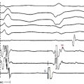
RF ablation within the coronary venous system is usually performed with a 3.5-mm open-irrigated-tip catheter at a power output of 15 to 25 W for up to 60 seconds (Fig. 27-4). If this catheter cannot be maneuvered to the ablation target site, a 5 Fr, 6 Fr, or 7 Fr ablation catheter may be used. For nonirrigated-tip catheters, the target temperature is usually set to 55°C to 60°C with a power output of 15 to 30 W. Impedance should be monitored during RF applications, and RF energy delivery should be stopped if impedance rises significantly. If RF energy delivery is limited, cryoablation using a 6-mm CryoAblation catheter (Medtronic, Minneapolis, Minn.) may be considered, although this catheter is less maneuverable than an RF catheter.8
Outcome
The outcome of the ablation procedure is a function of the proximity of the ideal target site to accessible portions of the coronary venous system as well as the ability to deliver an effective amount of ablative energy to the target site. Despite the anatomical constraints, ablation via the coronary venous system has yielded success rates of approximately 70%. Using the coronary venous system for mapping and ablation can potentially result in a lower complication rate than the percutaneous pericardial approach because damage to the RV or extracardiac structures is less likely to occur.7
Coronary artery injury is an ever-present risk, especially near the proximal part of the anterior interventricular vein. Arterial injury, including thrombosis, medial necrosis, and hyperplasia, is inversely proportional to vessel diameter; there is little evidence of injury when vessel diameter exceeds 0.5 to 1.0 mm. Similar findings were reported for cryoablation. As noted, coronary angiography should be performed before delivering RF energy near or within a branch of the CS to determine whether there are any branches of the right or left coronary artery in proximity to the ablation site.7
1. Cano O., Hutchinson M., Lin D., et al. Electroanatomic substrate and ablation outcome for suspected epicardial ventricular tachycardia in left ventricular nonischemic cardiomyopathy. J Am Coll Cardiol. 2009;54:799-808.
2. Garcia F.C., Bazan V., Zado E.S., et al. Epicardial substrate and outcome with epicardial ablation of ventricular tachycardia in arrhythmogenic right ventricular cardiomyopathy/dysplasia. Circulation. 2009;120:366-375.
3. Sacher F., Roberts-Thomson K., Maury P., et al. Epicardial ventricular tachycardia ablation a multicenter safety study. J Am Coll Cardiol. 2010;55:2366-2372.
4. Aliot E.M., Stevenson W.G., Mendral-Garrote J.M., et al. EHRA/HRS Expert Consensus on Catheter Ablation of Ventricular Arrhythmias: developed in a partnership with the European Heart Rhythm Association (EHRA), a Registered Branch of the European Society of Cardiology (ESC), and the Heart Rhythm Society (HRS); in collaboration with the American College of Cardiology (ACC) and the American Heart Association (AHA). Heart Rhythm. 2009;6:886-933.
5. Haqqani H.M., Morton J.B., Kalman J.M. Using the 12-lead ECG to localize the origin of atrial and ventricular tachycardias. 2. Ventricular tachycardia. J Cardiovasc Electrophysiol. 2009;20:825-832.
6. Natale A., Raviele A., Al-Ahmad A., et al. Venice Chart International Consensus document on ventricular tachycardia/ventricular fibrillation ablation. J Cardiovasc Electrophysiol. 2010;21:339-379.
7. Daniels D.V., Lu Y.Y., Morton J.B., et al. Idiopathic epicardial left ventricular tachycardia originating remote from the sinus of Valsalva: electrophysiological characteristics, catheter ablation, and identification from the 12-lead electrocardiogram. Circulation. 2006;113:1659-1666.
8. Baman T.S., Ilg K.J., Gupta S.K., et al. Mapping and ablation of epicardial idiopathic ventricular arrhythmias from within the coronary venous system. Circ Arrhythm Electrophysiol. 2010;3:274-279.
9. Tedrow U., Stevenson W.G. Strategies for epicardial mapping and ablation of ventricular tachycardia. J Cardiovasc Electrophysiol. 2009;20:710-713.
10. d’Avila A., Scanavacca M., Sosa E., et al. Pericardial anatomy for the interventional electrophysiologist. J Cardiovasc Electrophysiol. 2003;14:422-430.
11. Yokokawa M., Tada H., Koyama K., et al. The characteristics and distribution of the scar tissue predict ventricular tachycardia in patients with advanced heart failure. Pacing Clin Electrophysiol. 2009;32:314-322.
12. Tian J., Jeudy J., Smith M.F., et al. Three-dimensional contrast-enhanced multidetector CT for anatomic, dynamic, and perfusion characterization of abnormal myocardium to guide ventricular tachycardia ablations. Circ Arrhythm Electrophysiol. 2010;3:496-504.
13. Desjardins B., Morady F., Bogun F. Effect of epicardial fat on electroanatomical mapping and epicardial catheter ablation. J Am Coll Cardiol. 2010;56:1320-1327.
14. d’Avila A. Epicardial catheter ablation of ventricular tachycardia. Heart Rhythm. 2008;5(6 Suppl):S73-S75.
15. Lachman N., Syed F.F., Habib A., et al. Correlative anatomy for the electrophysiologist. I. The pericardial space, oblique sinus, transverse sinus. J Cardiovasc Electrophysiol. 2010;21:1421-1426.
16. Zeppenfeld K., Stevenson W.G. Ablation of ventricular tachycardia in patients with structural heart disease. Pacing Clin Electrophysiol. 2008;31:358-374.
17. Vest J.A., Seiler J., Stevenson W.G. Clinical use of cooled radiofrequency ablation. J Cardiovasc Electrophysiol. 2008;19:769-773.
18. Lustgarten D.L., Spector P.S. Ablation using irrigated radiofrequency: a hands-on guide. Heart Rhythm. 2008;5:899-902.
19. Di Biase L., Burkhardt J.D., Pelargonio G., et al. Prevention of phrenic nerve injury during epicardial ablation: comparison of methods for separating the phrenic nerve from the epicardial surface. Heart Rhythm. 2009;6:957-961.
20. Fan R., Cano O., Ho S.Y., et al. Characterization of the phrenic nerve course within the epicardial substrate of patients with nonischemic cardiomyopathy and ventricular tachycardia. Heart Rhythm. 2009;6:59-64.
21. Michowitz Y., Mathuria N., Tung R., et al. Hybrid procedures for epicardial catheter ablation of ventricular tachycardia: value of surgical access. Heart Rhythm. 2010;7:1635-1643.
22. Habib A., Lachman N., Christensen K.N., Asirvatham S.J. The anatomy of the coronary sinus venous system for the cardiac electrophysiologist. Europace. 2009;11(Suppl 5):v15-v21.
23. Ho S.Y., Sanchez-Quintana D., Becker A.E. A review of the coronary venous system: a road less traveled. Heart Rhythm. 2004;1:107-112.
24. Singh J.P., Houser S., Heist E.K., Ruskin J.N. The coronary venous anatomy: a segmental approach to aid cardiac resynchronization therapy. J Am Coll Cardiol. 2005;46:68-74.