Basic Emergency Ultrasound
 Key Points
• Emergency ultrasound is frequently used by emergency medical providers for the management of patients in the emergency department for a variety of indications.
• Emergency ultrasound focuses on answering a specific question that has an impact on patient care.
• Applications for emergency ultrasound are expanding rapidly and having a positive impact on patient care.
Introduction
Distinction must be made between EUS and ultrasound performed by other specialties. The American College of Emergency Physicians (ACEP) has defined EUS as “the medical use of ultrasound for the bedside diagnostic evaluation of emergency medical conditions and diagnoses, resuscitation of the acutely ill, critically ill or injured, guidance of high risk or difficult procedures, monitoring of certain pathologic states and as an adjunct to therapy.”1 EUS is performed or directly supervised by emergency physicians in a variety of settings. Importantly, EUS is primarily distinguished from consultant-performed ultrasound in that it is a goal-directed, focused ultrasound examination.2 In short, EUS seeks to answer a brief or “yes or no” question. For example, in a patient with a complaint of abdominal pain and a positive urine pregnancy test, EUS seeks to answer the question “Is an intrauterine pregnancy present?” to guide diagnosis and treatment of the patient. Ultrasound performed by a consultant answers the question in a more expansive manner. For example, in the aforementioned patient, ultrasound performed by radiology or obstetrics and gynecology seeks to evaluate all the organs of the pelvis and to describe any abnormalities identified.
What We Are Looking For
The most common uses for EUS are listed in Box 1. Additionally, the ACEP released the Emergency Ultrasound Imaging Criteria Compendium in 2006,3 which further elucidates and defines the indications, technique, and interpretation of each of the eight primary types of bedside ultrasound. Although this list is extensive, applications for EUS continue to be refined and grow as emergency physicians respond to the challenges of patient care.
Physics of Ultrasound
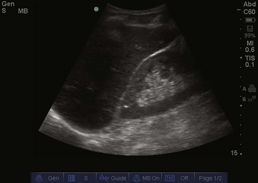
Tissues that are similar to water transmit sound waves very well and reflect less sound back to the transducer. Examples of these types of tissue in the body are the bladder, blood within the arteries and veins, and the vitreous humor of the eye. These tissues are seen as black or anechoic (without echoes) on the screen (Fig. 1). Conversely, tissue that has less water and is more dense reflects most or all of the sound waves that strike it. Examples of these types of tissue in the body are bones, tendons, and gallstones. These tissues are seen as white or hyperechoic (a lot of echoes) on the screen (Fig. 2). Continuing this logic, all other tissues that are somewhere in the middle of these textures fall into the range of shades of gray (Fig. 3). Objects that are mostly solid but contain some water are a lighter shade of gray, whereas objects that contain more water but are somewhat solid are a darker shade of gray.
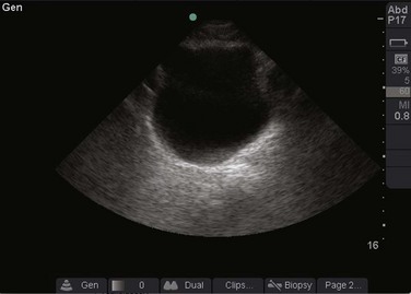
Fig. 1 Ultrasound image of the bladder.
Note that urine in the bladder, which is similar to fluid or water, is black or anechoic.
Selecting a Transducer
The type of transducer selected determines which frequencies are available to evaluate the tissue chosen. When attempting to select a transducer, it is helpful to think of the goals of your examination. Transducers are broadly divided into two types: high frequency and low frequency. High-frequency transducers allow excellent resolution but are limited in depth of penetration (Fig. 4). Evaluation of soft tissue for a foreign body or abscess is an example of the type of bedside ultrasound that would be best with a high-frequency transducer. Conversely, low-frequency transducers allow greater depth of penetration but do not provide as much resolution (Fig. 5). Evaluation of the abdominal aorta or the gallbladder is an example of the type of bedside ultrasound that would be best with a low-frequency transducer. Within each class there are multiple types of transducers distinguished by the shape of the transducer and the way that the sound waves are propagated.
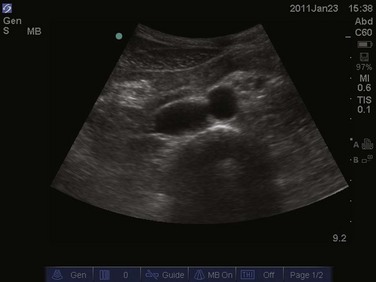
Image Orientation
Orientation is frequently the most difficult task for beginning sonographers. Each transducer has a dot or line on one side, known as an indicator (Fig. 6). This indicator corresponds to a dot or mark on the screen, which is typically on the left side of the screen (Fig. 7). By convention, when performing ultrasonography, the indicator is typically pointed toward the patient’s right side or toward the patient’s head. Echocardiography is an exception and its orientation is discussed further in Chapter 5. When the indicator is pointed toward the patient’s right, a transverse image is obtained, similar to that obtained with a computed tomography scan (Fig. 8). In this type of image, objects on the right side of the screen are on the left side of the patient’s body and objects on the left side of the screen are on the patient’s right side (Fig. 9). Objects closer to the top of the screen are closer to the surface and objects at the bottom of the screen are deeper within the body. When the indicator is pointed toward the patient’s head, a sagittal or coronal image is obtained (Fig. 10). In this type of image, objects on the left side of the screen are closer to the patient’s head (more superior) and objects on the right side of the screen are closer to the patient’s feet (more inferior). As just noted, objects at the top of the screen are closer to the surface and objects at the bottom of the screen are deeper within the body (Fig. 11).
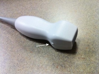
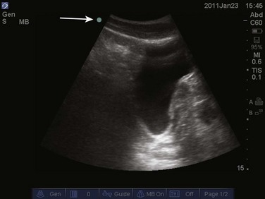
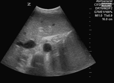
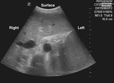
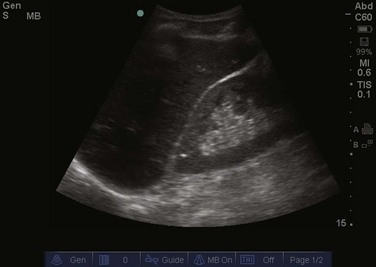
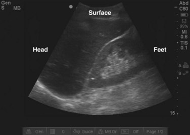
Image Manipulation and Artifacts
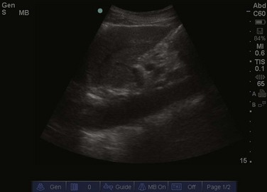
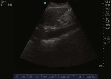
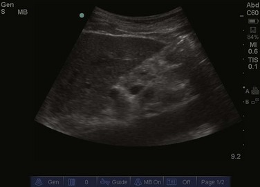
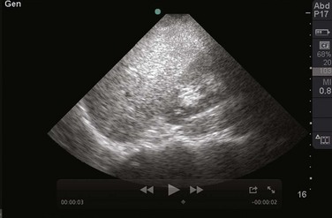
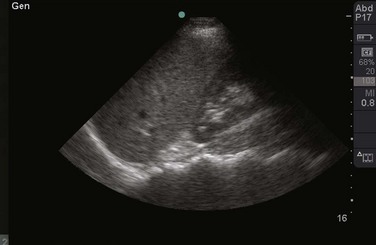
Once an image has been obtained, the depth of the screen should be adjusted to focus on the area of interest (Fig. 12). Most ultrasound machines have a depth knob or set of buttons. Selecting too great a depth prevents the sonographer from achieving the best possible magnification and resolution of the area of interest (Fig. 13). Selecting too shallow a depth may prevent the sonographer from viewing the entire area of interest and result in missing important details (Fig. 14).
The gain button is another setting that is frequently manipulated. Increasing the gain increases the strength of the echoes returning to the transducer. This makes the image appear brighter. It should be noted that increasing the gain will not improve the overall clarity of an image (Figs. 15 and 16). Gain can be thought of as the volume knob on a radio. When the radio is set between stations, you will hear some static with some music. Turning the volume higher will increase the sound of the music but will also increase the sound of the static. This is analogous to increasing the gain on a poor-quality image, a common mistake made by beginning sonographers. The best possible image should be obtained before attempting to increase the gain.
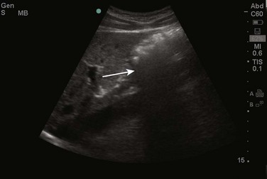
One of the most frequently encountered artifacts is acoustic shadowing. When the ultrasound wave strikes a hyperechoic object, it is reflected strongly and sends almost all of its energy back to the transducer. The transducer recognizes that there is a dense, hyperechoic object present but is unable to define the objects directly behind it because few sound waves pass through the object. This results in a strong black vertical line, or shadow, extending deep to the white, hyperechoic object. This artifact can be a hindrance, such as when ribs create shadows and impede views of the chest and abdomen (Fig. 17). Shadowing can also be helpful in identifying abnormalities, such as gallstones or foreign bodies (Fig. 18).
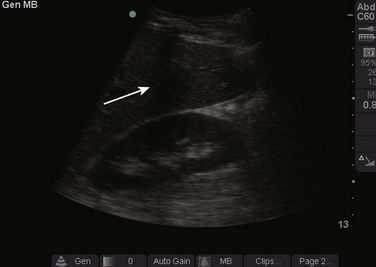
Fig. 17 Example of acoustic shadowing as caused by the ribs.
A dark black line can be seen emanating from the ribs (arrow).
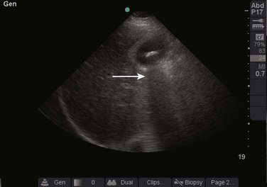
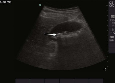
Fig. 18 Example of acoustic shadowing caused by gallstones.
A dark black line can be seen emanating from the gallstones (arrow).
The presence of air creates several artifacts that may frustrate the sonographer. In general, ultrasound waves do not interact well with air. Air causes the waves to scatter, which results in a hazy, gray appearance that obscures underlying objects. Another type of artifact produced by air, a “dirty shadow,” might be produced by the interface of the sound wave with gas (Fig. 19). This type of shadowing is grainier and more irregular than that seen with the “clean shadowing” described earlier.
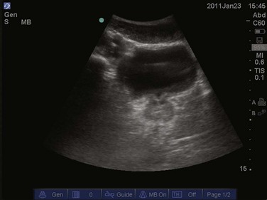
An artifact that frequently proves helpful to the sonographer is acoustic enhancement, which occurs when the ultrasound waves encounter a fluid-filled structure. Such structures, as with water, conduct sound waves very well with little loss of energy. More ultrasonic energy is available when the sound reaches the object on the other side of the fluid. This results in a brighter, clearer image immediately behind the fluid-filled object. An example of this effect is ensuring a full bladder before performing a transabdominal scan of the pelvis (Fig. 20). The bladder acts to enhance the sound wave, thereby providing a clearer image of the uterus and adnexa.
Other Ultrasound Modes
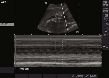
M-mode ultrasound is used to evaluate objects that are in motion and is most frequently used by beginning sonographers to evaluate fetal heart tones. More advanced sonographers may use M-mode to evaluate the valves of the heart or the inferior vena cava. M-mode allows the sonographer to evaluate the typical ultrasound image simultaneously with a distinctive waveform. This waveform represents time on the horizontal axis and movement of objects on the screen on the vertical axis. When an object moves toward the transducer, it is represented by an upward deflection. When an object moves away from the transducer, it is represented by a downward deflection. The up and down movement of an object (e.g., a fetal heart valve) causes a sinusoidal waveform (Fig. 21).
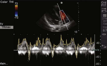
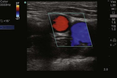
D-mode, or Doppler, relies on the phenomenon of the Doppler or frequency shift to evaluate objects that are moving as they are imaged (e.g., blood within an artery). Spectral Doppler uses this frequency shift to generate a continuous waveform that can be used to glean information about the object in question. For example, the speed of blood flow across a valve can be calculated with spectral Doppler (Fig. 22). Color Doppler simplifies the Doppler signal and assigns color (typically red or blue) to an object in motion to indicate the direction of movement (typically toward or away from the transducer) (Fig. 23). This mode is also frequently used by sonographers to identify sources of blood flow, such as to identify the pulsatile quality of an artery. Finally, power Doppler assigns only one color to indicate the presence of blood flow but has increased sensitivity. This mode is ideal for detecting blood flow within low-flow states, where traditional color Doppler may not be sensitive enough to detect flow.
1 Emergency ultrasound guidelines, ACEP policy statement. Ann Emerg Med. 2009;53:550–570.
2 Mateer J, Plummer D, Heller M, et al. Model curriculum for physician training in emergency ultrasonography. Ann Emerg Med. 1994;23:95–102.
3 ACEP emergency ultrasound imaging criteria compendium. http://www.acep.org/Content.aspx?id=32182, April 2006. Available at