[level-membership-for-anesthesiology-category]
Chapter 23 Electrical hazards and their prevention
Mains electricity supply
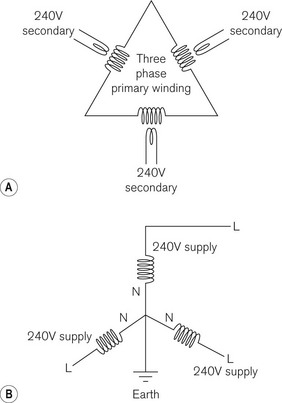
In cables carrying DC, one cable is designated positive and the other negative, which is not the case with AC cables. Fig. 23.1A shows how a three phase, 16 kV primary winding of a substation transformer steps the voltage down to a three phase 240 V root-mean-square supply (325 V peak). It also shows how these secondary 240 V windings are linked together and connected to earth at the ‘star point’ (Fig. 23.1B). For each 240 V supply, therefore, one end is deemed ‘live’ and the end connected to earth at the star point is deemed ‘neutral’.
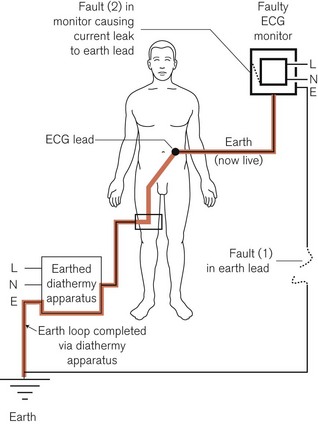
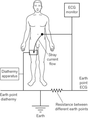
Because of this earthing of the neutral conductor at the power station, any person or object who is also connected to earth would complete an electric circuit by touching the live conductor, even if no contact were made with the neutral one. Fig. 23.2 shows how, under certain conditions, the circuit connecting a patient to a live lead may be completed by, for example, an earthed diathermy plate, resulting in fatal electrocution. However, in most modern diathermy machines, this plate is isolated from earth as far as mains current is concerned (see Chapter 24). Furthermore, here in this example of a faulty monitor, an additional interruption of the neutral cable would result in the apparatus not working. However, because the live cable is still functioning, any contact with the (‘live’) casing would lead to electrocution of an inadvertently earthed user.
Stringent precautions should be taken to ensure that the polarities are correctly defined and connected for all mains electrical apparatus. Electrical accidents can be minimized by careful, regular maintenance by qualified personnel. It cannot be overemphasized that, if a fault exists, the apparatus should be removed from use and the services of a competent technician sought. The current international standard regulating electromedical equipment, IEC 60601-1, lays down quite specific testing regimens for electromedical equipment before use.1,2
The inclusion of a lead which connects the metal chassis, frame and enclosure of the apparatus to earth ensures that under faulty conditions the enclosure is prevented from becoming live, and is thus called the ‘earth’ lead. The faults in Fig. 23.2 show a break in the earth lead to the metal enclosure of the monitor (1); this allows a second fault within the monitor (2) to render the apparatus dangerous to the patient. This is discussed further in the section below, on Class I equipment.
Apparatus can be rendered safer by the inclusion of a fuse in the electrical circuit. This may be installed in the mains supply circuit, in the plug of the electrical lead to the apparatus, or in the apparatus itself. It usually consists of a fine gauge wire, which melts if the current passing through exceeds that against which they are intended to offer protection. So, in Fig. 23.2, if the earth lead of the monitor were intact, the fault consisting of a current leak between the apparatus and its enclosure, assuming adequate leakage current and low enough fuse rating, would result in a fuse in the live wire melting, breaking the continuity of the electrical circuit and the apparatus being rendered harmless. However, there is a risk that the fuse may not protect against electric shock. This can happen if someone is in contact with the equipment as the fault develops and before the fuse has time to melt (see below). Fuses are used mainly to interrupt the electric supply in the event that the current passing through the equipment exceeds a predetermined level that might cause overheating or damage. Other types of safety devices are mentioned later in the chapter.
Pathophysiological effects of electricity
The pathophysiological effects of electric current passing through the human body include:
• resistive heating of the tissue and thermal burns
• electrical stimulation of excitable tissues, such as respiratory muscles and the heart
• electrochemical effects (electrolysis), when DC can cause chemical burns
The body may be considered electrically to be an electrolyte (a good conductor) in a leathery bag (a poor conductor, an insulator). However, the resistance of the skin is very variable (Table 23.1).
| SKIN TYPE | ELECTRICAL RESISTANCE kΩ cm−2 |
|---|---|
| Mucous membranes | 0.1 |
| Vascular areas (volar aspect of arm, inner thigh) | 0.3–10 |
| Wet skin: in the bath | 1.2–1.5 |
| Sweat | 2.5 |
| Dry skin | 10.0–40 |
| Sole of the foot | 100–200 |
| Heavily calloused palm | 1000–2000 |
Other tissues have diverse electrical resistances, which can be grouped as follows:
There is, however, an idiosyncratic relationship between whole body electrical impedance (AC resistance) and the applied voltage. At low voltages, 25–100 volts, it depends on the state of the skin and area of contact. At 250 volts and higher, the total body impedance falls to 2000–5000 ohm, irrespective of the contact area and the current pathway.3
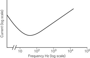
The effects of electric current upon excitable tissues such as muscle and nerve depend not only on current and time, but also on the frequency.4,5 It is one of the ironies of life that the commonly used mains frequencies of 50 Hz (UK, Europe) or 60 Hz (USA) are the frequencies at which the excitable tissues are at greatest risk of excitation and damage (Fig. 23.3).
In greatest danger is the heart, as it is susceptible to induced arrhythmias as well as permanent damage. The direction of the current pathway through the heart is also important. Clinical studies suggest that sudden death from ventricular fibrillation is more likely with current passing ‘horizontally’ from hand to hand, whereas heart muscle damage is more often associated with a ‘vertical’ current pathway.6
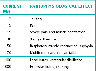
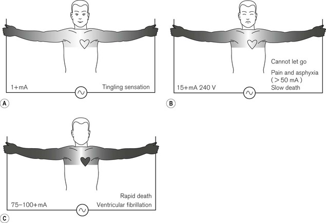
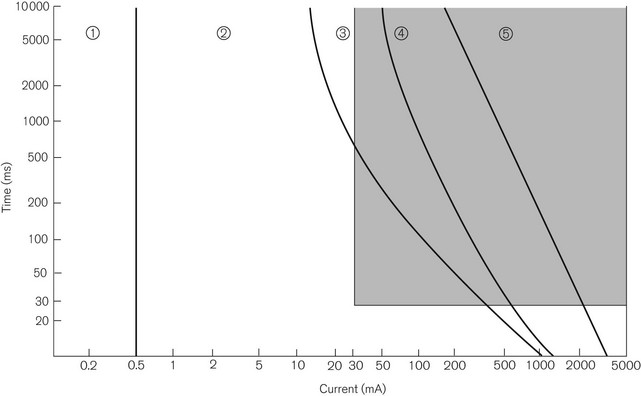
The effects of hand-to-hand 50 Hz AC on the body are shown in Table 23.2 and Fig. 23.4. Fig. 23.5 shows a plot of current magnitude against duration in relation to pathophysiological effects.
Direct current (DC) electric shock tends to result in:
Even very low imperceptible DC may produce electrochemical burns if the current is allowed to pass for long enough, for example from swallowed button-sized 1.5 V hearing aid type batteries.7
Alternating current (AC) electric shock:
• is about three times more dangerous than DC, at similar current flows
• produces continuous muscle contractions (tetany) at 40–110 Hz
• induces grip and pull as flexor muscles are much stronger than extensor muscles. If a person were to be holding onto a faulty conductor, he would be unable to let go. This prolongs the duration of the effect of the current
Accidents associated with the mains electricity supply
These will now be discussed in some detail.
Electrocution
As shown in Fig. 23.4, electrocution can cause death relatively slowly by tonic contraction of the respiratory muscles, leading to asphyxia, or more rapidly by ventricular fibrillation. The onset of ventricular fibrillation may be delayed, being preceded by ventricular tachycardia, which causes circulatory failure, but which may revert to normal rhythm if stopped in time.
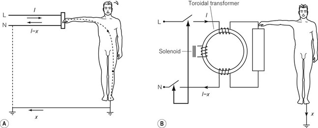
As discussed earlier, the neutral pole of the mains electricity supply is connected to earth at the star point, a point at the power station which is thus remote from the patient. Since all conductors have some resistance, however low, there is therefore a small voltage drop between the patient end of the neutral conductor and the star point, i.e. they represent non-identical earth points. The patient end of the neutral conductor may, therefore, not be exactly at earth potential. This difference in potential along the neutral lead may facilitate stray capacitative or inductive currents in a circuit, which includes the patient connected to earth. Similarly, earthed electrodes may be attached to more than one part of the patient and from more than one piece of equipment supplied by different mains sockets, which may also facilitate stray capacitative or inductive currents in a circuit, which includes the patient. This is shown in Fig. 23.6. Therefore, it is recommended that the earth connections on all the socket outlets in a single clinical area be interconnected by a low-resistance conductor to minimize voltage differences between them. Similarly, all exposed metal objects, such as metal pipes and radiators, should be interconnected to a good earth.
Microshock
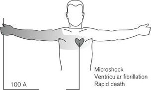
So far only macroshock has been discussed. Fig. 23.4 shows the effect of a current passing between the extremities. When it passes across the patient’s trunk, only a small part of it passes through the heart. However, many modern medical, surgical and critical care procedures involve the placement of electrodes on, within or close to the heart, e.g. a pulmonary artery catheter or even a transduced arterial line by virtue of its column of electrolyte. Under these circumstances, a very much smaller current, possibly as low as 100 µA, can result in ventricular fibrillation (Fig. 23.7) because all the current passes through the heart. A very small potential, such as the stray voltage in the mains neutral lead, could be sufficient to produce electrocution in this way. This phenomenon is known as microshock.
Shock protection
1. Installing an isolating transformer, the output of which is carefully isolated from earth
2. Detecting unwanted currents passing to earth by a device that will sound a warning or automatically switch the supply.
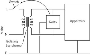
Both have advantages and disadvantages. An isolating transformer may supply all the outlets for a whole operating room or theatre suite. It works on the principle that the output from the transformer is free from earth. Should the apparatus develop a fault, the earth leakage current is sensed almost instantaneously by a relay, which then trips a switch in the transformer input and cuts the power supply to it (Fig. 23.8). Apart from the expense, problems arise if there are several appliances in use and each of these has a small earth leakage current that is harmless in itself. The sum of all these currents may be sufficient to trip the relay and cut off the power to a monitor or other mains powered anaesthetic equipment. Likewise, a fault in one piece of apparatus may cause the power to another be cut off. If the relay operates an alarm rather than a circuit breaker, it may be ignored by staff. A better alternative is to include a small isolating transformer in the circuitry of each individual item of mains operated electromedical equipment, which can be connected to the patient. The patient circuit is, therefore, earth-free and said to be fully floating. The enclosure of the equipment may be earthed (or completely insulated see below).
The second method of improving safety is to install a current-operated earth-leakage circuit breaker (COELCB), also known as an ‘earth trip’ or residual current circuit breaker (RCCB) (Fig. 23.9). This may be installed in the electrical supply to the whole operating room or theatre suite, or may be installed in each item of equipment. The live and neutral conductors each take a couple of turns or so (but both exactly the same number) around the core of a toroidal transformer. A third winding is connected directly to the coil of the relay that operates the circuit breaker. If the current in the live and neutral conductors is the same, the magnetic fields cancel themselves out. If they differ, there is a resultant magnetic field, which induces a current in the third winding and this causes the relay to operate and break the circuit. A difference of as little as 30 mA can trip the COELCB in as little as 30 ms or be used to operate an alarm. It may be manually reset and may also have a test button to check its operation. COELCBs may have similar problems to isolating transformers, but are less expensive. They operate so quickly and at such low earth leakage currents, that they greatly reduce the possibility of serious electric shock. The shaded area of Fig. 23.5 shows the protection afforded by a COELCB.
Classification of electromedical equipment to ensure electrical safety1,8
The international standard governing electromedical equipment, IEC 60601-1, is based on a concept of risk management; it tries to assess and control risk in the device design, manufacture and intended use. The standard requires that there be two levels of protection for the patient or, indeed, the operator of the equipment, so that even if one level fails, harm may yet be avoided. It allows the use of three mechanisms to provide those two levels;9 these are insulation, protective earthing and protective impedance, and the following classifications use these mechanisms to different extents.
Class I equipment
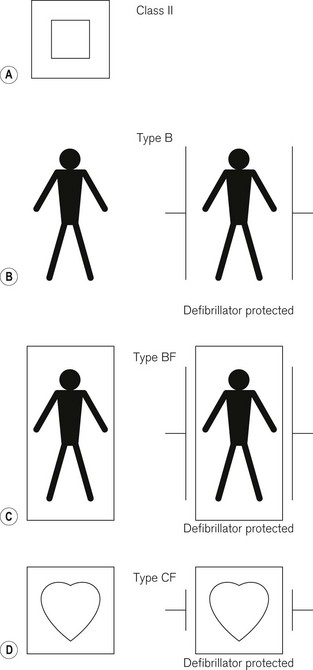
This includes household electrical items. The electrical apparatus itself is connected to live and neutral conductors and insulated from the metal casing. The casing, which can be touched by the user, is connected to the earth lead, which normally safely conducts any earth leakage current to earth. In the event of a fault in the apparatus in which there is current leakage from the apparatus to its casing, the earth connection grounds this ‘earth leakage current’. A fuse in the live wire plug connection (UK) melts and the apparatus becomes disconnected from the mains. The user is thus protected from electric shock. However, if the earth connection is also faulty, such protection is lost and there is a potentially hazardous enclosure leakage current (touch current) through inadvertent contact with the apparatus, or patient leakage current through the patient applied parts of the device2 (Fig. 23.2). Testing of these various different leakage currents of the device before use is mandatory according to IEC60601-1. Not all devices with an earth lead are necessarily Class I; for example, some devices have an earth lead designed for screening the equipment, rather than carrying a leakage current. Furthermore, a device with an enclosure that appears to be made of plastic may still be Class I and should be tested as such.
Class III equipment
Class I, II, and III equipment may be subdivided into the following:
Type B equipment (Fig. 23.10B)
Type BF equipment (Fig. 23.10C)
This is as type B equipment, except that the part applied to the patient is isolated from the rest of the apparatus. This confers a degree of safety such that the maximum earth leakage current under a single fault condition is not exceeded, even if 1.1 times the maximum rated voltage is applied between earth and the patient attachment. It is still not safe enough for direct attachment to the heart.
Burns
Where electric current is passed through the skin, the heat generated is proportional to the square of the current flow and the electrical resistance of the surface area of skin involved, as indicated above. Depending on the amount of heat produced, the area over which it is applied and the rate of cooling by the circulation, burns may result. This is discussed further in Chapter 26, in connection with diathermy.
Sparks and static electricity
There is, therefore, an upper and a lower limit to the permissible electrical resistance between any part of the antistatic floor of the operating room and earth. The resistance between two electrodes set 60 cm apart should nowhere be less than 20 kilo ohm (kΩ) or more than 5 mega ohm (MΩ). All mobile operating equipment in the operating room and anaesthetic room should make electrical contact with the floor. Anaesthetic machines and trolleys have wheels whose tyres are constructed of antistatic (conducting) rubber. In the absence of such precautions a metal chain, one end of which is attached to the frame of the trolley, is allowed to dangle on the floor so that at least three links are in contact with the floor. The chains can be damaged or kept off the floor and are, therefore, a poor substitute for conducting rubber wheels. Similarly, all footwear worn by staff should contain conducting material. Periodic tests should be carried out to ensure that the resistance of the above items remains within prescribed limits.
Fire and explosion
For these to occur, there are three prerequisites: combustible material (fuel), oxidant to support combustion and a source of ignition.10–12 These risks arise from the following sources:
• The use of high partial pressure of oxygen (pressurized oxygen and high oxygen concentrations)
• The use of flammable anaesthetic agents and of solvents for cleaning and skin preparation, such as alcohol.
Zone of risk
• There should be no naked flames
• All electric switches should be spark-proof and electric plugs should be ‘captive’ while the switch is turned on
• All parts, especially rubber tubing, etc., of anaesthetic apparatus should be constructed of conductive (antistatic) rubber or other material, and the operating room floor should be antistatic. Antistatic rubber, containing carbon, has sufficient conductivity to leach away static electricity, and yet sufficient resistance to prevent so fast a discharge that a spark occurs.
In 1956 in UK the original working party looking into the risks of explosion in clinical settings defined the zone of risk as the whole anaesthetic room and operating room where the anaesthetic machine was mobile. Since 1956, with non-flammable anaesthetic agents largely superceding cyclopropane and ether, there was a dramatic fall in the number of explosions. Subsequently, in 1970, the Association of Anaesthetists of Great Britain and Ireland changed the definition of the zone of risk to 25 cm around the gas pathways of the anaesthetic machine and breathing system. Non-spark-proof switches and sockets are permissible outside the zone of risk, providing they are permanently attached to the wall of the operating room, and that electrical outlets are 40 cm above the floor to prevent damage to cables.
1 IEC. International standard. IEC 60601-1. Medical electrical equipment – Part 1: General requirements for basic safety and essential performance, 3rd ed. Geneva: Bureau Central de la Commission Electrotechnique Internationale; 2005.
2 http://www.ebme.co.uk/arts/safety/part6.htm.
3 Beiglemeyer G. Effects of current passing through the human body and the electrical impedance of the human body. In: A guide to IEC Report 479. Berlin: vde Verlag gmbh; 1987.
4 IEC. Effects of current passing through the human body. In: IEC 479–1 General aspects. Geneva: Bureau Central de la Commission Electrotechnique Internationale; 1984.
5 IEC. Effects of current passing through the human body. In: IEC 479–2 Special aspects. Geneva: Bureau Central de la Commission Electrotechnique Internationale; 1987.
6 Fontanarosa PB. Electric shock and lightening strike. Ann Emerg Med. 1993;22:378–387.
7 Yoshikawa T, Asai S, Takekawa Y, Kida A, Ishikawa K. Experimental investigation of battery induced esophageal burn injury in rabbits. Crit Care Med. 1972;25:2039–2044.
8 Al-Shaikh B, Stacey S. Essentials of anaesthetic equipment, 2nd ed. London: Churchill Livingstone; 2002. 175–80
9 Eisner L, Brown RM, Modi D. Safety requirements: understanding. IEC 60601-1. Geneva: Medical Electronics Manufacturing Archives; 2004.
10 MacDonald A. A short history of fires and explosions caused by anaesthetic agents. Br J Anaesth. 1994;72:710–722.
11 MacDonald A. A brief historical review of non-anaesthetic causes of fires and explosions in the operating room. Br J Anaesth. 1994;73:843–846.
12 Vickers MD. Hazards in the operating theatre. Fires and explosions. Ann R Coll Surg Engl. 1973;52:354–357.
Hull CJ. The electrical hazards of patient monitoring. In: Monitoring in anaesthesia and intensive care. London: Hutton & Prys Roberts Saunders; 1994. Although now a little out of date, this chapter explains many aspects of electrical safety well
Magee P, Tooley M. Environmental and electrical safety. In: The physics, clinical measurement and equipment of anaesthetic practice. Oxford: Oxford University Press; 2005.
[/level-membership-for-anesthesiology-category][not-level-membership-for-anesthesiology-category]
Chapter 23 Electrical hazards and their prevention
Mains electricity supply
In cables carrying DC, one cable is designated positive and the other negative, which is not the case with AC cables. Fig. 23.1A shows how a three phase, 16 kV primary winding of a substation transformer steps the voltage down to a three phase 240 V root-mean-square supply (325 V peak). It also shows how these secondary 240 V windings are linked together and connected to earth at the ‘star point’ (Fig. 23.1B). For each 240 V supply, therefore, one end is deemed ‘live’ and the end connected to earth at the star point is deemed ‘neutral’.
Because of this earthing of the neutral conductor at the power station, any person or object who is also connected to earth would complete an electric circuit by touching the live conductor, even if no contact were made with the neutral one. Fig. 23.2 shows how, under certain conditions, the circuit connecting a patient to a live lead may be completed by, for example, an earthed diathermy plate, resulting in fatal electrocution. However, in most modern diathermy machines, this plate is isolated from earth as far as mains current is concerned (see Chapter 24). Furthermore, here in this example of a faulty monitor, an additional interruption of the neutral cable would result in the apparatus not working. However, because the live cable is still functioning, any contact with the (‘live’) casing would lead to electrocution of an inadvertently earthed user.
Stringent precautions should be taken to ensure that the polarities are correctly defined and connected for all mains electrical apparatus. Electrical accidents can be minimized by careful, regular maintenance by qualified personnel. It cannot be overemphasized that, if a fault exists, the apparatus should be removed from use and the services of a competent technician sought. The current international standard regulating electromedical equipment, IEC 60601-1, lays down quite specific testing regimens for electromedical equipment before use.1,2
The inclusion of a lead which connects the metal chassis, frame and enclosure of the apparatus to earth ensures that under faulty conditions the enclosure is prevented from becoming live, and is thus called the ‘earth’ lead. The faults in Fig. 23.2 show a break in the earth lead to the metal enclosure of the monitor (1); this allows a second fault within the monitor (2) to render the apparatus dangerous to the patient. This is discussed further in the section below, on Class I equipment.
Apparatus can be rendered safer by the inclusion of a fuse in the electrical circuit. This may be installed in the mains supply circuit, in the plug of the electrical lead to the apparatus, or in the apparatus itself. It usually consists of a fine gauge wire, which melts if the current passing through exceeds that against which they are intended to offer protection. So, in Fig. 23.2, if the earth lead of the monitor were intact, the fault consisting of a current leak between the apparatus and its enclosure, assuming adequate leakage current and low enough fuse rating, would result in a fuse in the live wire melting, breaking the continuity of the electrical circuit and the apparatus being rendered harmless. However, there is a risk that the fuse may not protect against electric shock. This can happen if someone is in contact with the equipment as the fault develops and before the fuse has time to melt (see below). Fuses are used mainly to interrupt the electric supply in the event that the current passing through the equipment exceeds a predetermined level that might cause overheating or damage. Other types of safety devices are mentioned later in the chapter.
Pathophysiological effects of electricity
The pathophysiological effects of electric current passing through the human body include:
• resistive heating of the tissue and thermal burns
• electrical stimulation of excitable tissues, such as respiratory muscles and the heart
• electrochemical effects (electrolysis), when DC can cause chemical burns
The body may be considered electrically to be an electrolyte (a good conductor) in a leathery bag (a poor conductor, an insulator). However, the resistance of the skin is very variable (Table 23.1).
| SKIN TYPE | ELECTRICAL RESISTANCE kΩ cm−2 |
|---|---|
| Mucous membranes | 0.1 |
| Vascular areas (volar aspect of arm, inner thigh) | 0.3–10 |
| Wet skin: in the bath | 1.2–1.5 |
| Sweat | 2.5 |
| Dry skin | 10.0–40 |
| Sole of the foot | 100–200 |
| Heavily calloused palm | 1000–2000 |
Other tissues have diverse electrical resistances, which can be grouped as follows:
There is, however, an idiosyncratic relationship between whole body electrical impedance (AC resistance) and the applied voltage. At low voltages, 25–100 volts, it depends on the state of the skin and area of contact. At 250 volts and higher, the total body impedance falls to 2000–5000 ohm, irrespective of the contact area and the current pathway.3
The effects of electric current upon excitable tissues such as muscle and nerve depend not only on current and time, but also on the frequency.4,5 It is one of the ironies of life that the commonly used mains frequencies of 50 Hz (UK, Europe) or 60 Hz (USA) are the frequencies at which the excitable tissues are at greatest risk of excitation and damage (Fig. 23.3).
In greatest danger is the heart, as it is susceptible to induced arrhythmias as well as permanent damage. The direction of the current pathway through the heart is also important. Clinical studies suggest that sudden death from ventricular fibrillation is more likely with current passing ‘horizontally’ from hand to hand, whereas heart muscle damage is more often associated with a ‘vertical’ current pathway.6
The effects of hand-to-hand 50 Hz AC on the body are shown in Table 23.2 and Fig. 23.4. Fig. 23.5 shows a plot of current magnitude against duration in relation to pathophysiological effects.
Direct current (DC) electric shock tends to result in:
Even very low imperceptible DC may produce electrochemical burns if the current is allowed to pass for long enough, for example from swallowed button-sized 1.5 V hearing aid type batteries.7
Alternating current (AC) electric shock:
• is about three times more dangerous than DC, at similar current flows
• produces continuous muscle contractions (tetany) at 40–110 Hz
• induces grip and pull as flexor muscles are much stronger than extensor muscles. If a person were to be holding onto a faulty conductor, he would be unable to let go. This prolongs the duration of the effect of the current
