Chapter 8 Coronary Computed Tomography Angiography
INTRODUCTION
Noninvasive cardiac imaging is of vital importance for the assessment of coronary artery disease.
TECHNICAL DEVELOPMENT OF SCANNERS
If the development of cardiac CT over the past decade is reviewed, it is noted that cardiac imaging was possible with 4-slice systems, but most research studies that were conducted removed a substantial number of coronary artery segments (up to 30%) from their analysis because of nonevaluability. This was in part as a result of presence of motion artifact (image blurring). The reason for the large amount of motion artifact with these systems is the slower gantry rotation speed of approximately 500 ms (resulting in a temporal resolution of 250 ms). The major improvement with 64-slice CT systems was in the reduction of the number of nonevaluable segments, which is in keeping with the improved temporal resolution. Typical gantry rotation speeds of 16-slice scanners are 420 ms to 370 ms (even though some remained at 500 ms at first), resulting in temporal resolutions typically ranging from 210 ms to 185 ms. This has caused the number of nonevaluable coronary artery segments to go down to on average approximately 6%. Keep in mind that temporal resolution and the resulting motion artifact is only one of the two major reasons for unevaluable segments, the other one being presence of dense coronary calcium. The next major step in the development of cardiac CT was the 64-slice MDCT generation. All major vendors have offered a 64-slice MDCT system, even though the number of slices is calculated in different ways. Some vendors have actually 64 equally sized detector rows within the gantry and have x-rays emitted from one focal spot in the x-ray tube. One vendor, however, uses 32 equally spaced detectors and two focal spots on the x-ray tube that alternate in emitting x-rays. Thus they acquire two different projections for each of the 32 detector rows, resulting in 64 individual projections.
TECHNICAL PRINCIPLES
Retrospective Gating versus Prospective Triggering
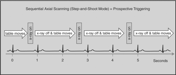
There are two general approaches to cardiac synchronization of the CT acquisition. One is prospective and “observes” the electrocardiogram (ECG) for a small number of heart beats (or more accurately the peak of the R-wave or R-peak) and then anticipates when the next R peak is to occur. Given the anticipated time point of the future R peak, the scanner will then only acquire x-ray projections in a prespecified phase of the cardiac cycle (usually late in diastole where the heart is most quiescent). This approach is called prospective triggering because the x-ray tube is triggered to shoot in a predefined cardiac phase. Data acquisition is in an axial fashion, and the table only moves in between heartbeats and is stationary during x-ray transmission. This approach has the advantage of having a low radiation dose to the patient, but it has a number of disadvantages. One of the major disadvantages is that typically only one dataset (or few similar ones) can be acquired in the anticipated cardiac cycle, which may not turn out to be of optimal image quality (Fig. 8-1).
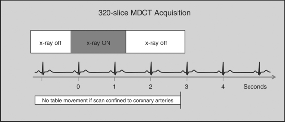
The newer 256- and 320-slice scanners use a modified step-and-shoot mode. Because their detectors cover a large volume, in many cases the entire heart, no table motion is necessary to acquire a coronary CTA dataset. Having the tube current turned on for approximately one entire heartbeat allows acquiring a dataset for analysis of cardiac anatomy and function. Theoretically, x-ray exposure can be limited to a short segment in diastole if only coronary artery visualization, and if no information on function is desired. Multi-phase reconstruction (to improve temporal resolution) would, however, require data acquisition during several consecutive cardiac phases (Fig. 8-2).
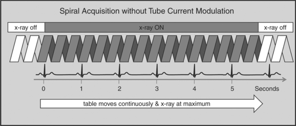
A radically different approach is retrospective gating (Fig. 8-3). Retrospective gating allows acquiring unlimited complete datasets in any phase of the cardiac cycle. This approach uses a spiral CT acquisition, in which the x-ray current remains turned on during the entire scan. The user may then in retrospect define what phase of the cardiac cycle to reconstruct. The major advantage of this approach is that the interpreter may decide to try a different phase of the cardiac cycle if the initial reconstruction demonstrates motion artifact. Another advantage is the ability to “edit” the ECG. ECG editing allows the user to select heartbeats that should not be used for reconstructions (e.g., premature ventricular contractions [PVCs]), or to correct trigger points that were not placed on an R peak by the computer algorithm. The major disadvantage of retrospective gating is the high radiation dose to the patient. For this reason a number of dose reduction strategies were developed.
Tube Modulation
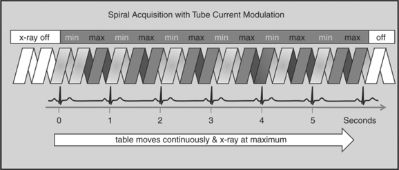
One of the most important dose reduction strategies in cardiac CT is ECG-correlated x-ray tube current modulation or short tube modulation. In this algorithm the scanner does perform a spiral acquisition using the retrospective gating method; however, it prospectively down regulates the x-ray tube current (typically in systole and usually down to approximately 20% of the maximum). This reduces the radiation dose to the patient during systole, but nevertheless allows for reconstructions of images in systole, if necessary. The penalty for reducing the tube current is a higher noise level. This approach is clearly a compromise trying to capture the advantages of both the prospective triggering and the retrospective gating acquisitions (Figure 8-4).
HALF-SCAN VERSUS MULTI-SEGMENT RECONSTRUCTION
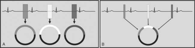
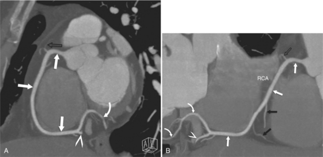
To capture images without blurring from rapid cardiac motion, it is important to achieve a high temporal resolution. Temporal resolution refers to the time it takes to collect all the data (projections) to generate an axial source image. The time it takes to collect these data (the temporal resolution) is dependent on how fast the CT gantry spins around the patient. In conventional CT, the temporal resolution is equal to the gantry rotation speed. There are, however, ways to improve the temporal resolution for cardiac CT imaging. Two algorithms can be applied, the “half-scan” reconstruction algorithm, or the “multi-segment reconstruction” algorithm (Fig. 8-5A, B).
SCAN ACQUISITION
Contrast Injection
There are a number of injection protocols that can be applied to coronary CTA. It is beyond the scope of this chapter to review all these. However, there are a number of common principles that are important to review. The intravenous catheter is ideally of large bore and placed in the right antecubital fossa. The right-sided injection is somewhat preferred because of a shorter route to the heart and because it avoids the crossing of dense contrast past the left internal mammary artery (LIMA) and the great vessels via the left innominate vein. This has the potential to cause streak artifact, which, for example, can hinder the assessment of a portion of a LIMA graft.
CORONARY ANATOMY
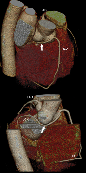
The RCA originates from the right sinus of Valsalva. The first RCA branch is the conus branch, which supplies the myocardium of the right ventricular outflow tract (RVOT). Occasionally the conus branch may have a separate ostium from the right sinus. The RCA gives rise to anterior right ventricular (RV) free wall branches and acute marginal branches that run along the angle that the anterior and inferior RV free walls form. The RCA is dominant in ≈80% of cases and runs in the right atrioventricular groove up to the crux of the heart (the point of the inferior cardiac surface where the atria and ventricles meet), where it bifurcates into a posterior descending artery (PDA) that runs within the inferior interventricular groove, and a posterior left ventricular branch (PLV) that supplies the inferior left ventricular (LV) wall (Figures 8-6, 8-7, 8-8). The PLV often gives rise to a small atrioventricular nodal branch at the crux of the heart. If the RCA is nondominant, it usually does not reach the crux of the heart, and the PDA and PLV are supplied by the left circumflex coronary artery (LCX).
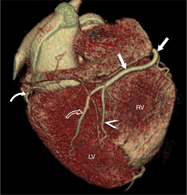
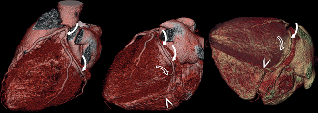
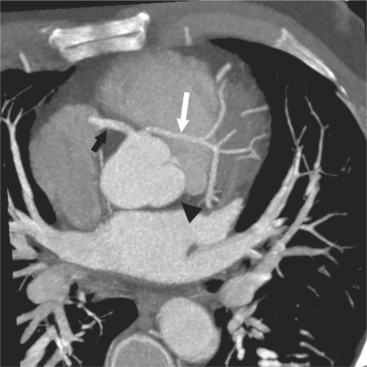
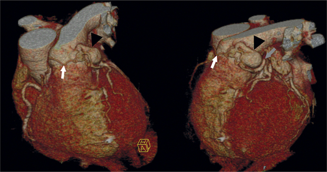
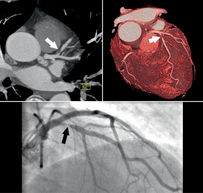
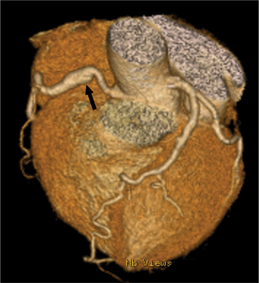
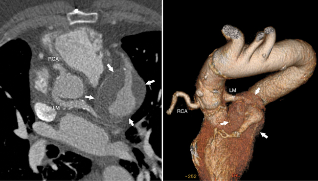
The left main coronary artery (LM) origin is usually more cephalad compared to the RCA ostium. The LM originates from the left sinus of Valsalva and bifurcates within 2 cm of its origin into the left anterior descending artery (LAD) and LCX (Figures 8-9, 8-10). Occasionally there is no LM, and the LAD and LCX both originate directly from the left sinus of Valsalva (Fig. 8-11). An LM trifurcation is a situation in which there is a third branch arising from the LM between the LAD and LCX (Fig. 8-12). This branch is called ramus intermedius.
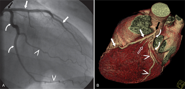
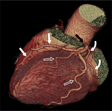
FIGURE 8-10 Normal coronary anatomy. Volume-rendered reconstruction of coronary computed tomography angiography shows the opposite end of the spectrum of normal (compared to Figure 8-9) with a large branching first diagonal branch (open white arrows) and a small left circumflex artery with no obtuse marginal branches. Note the left anterior descending artery (white arrows).
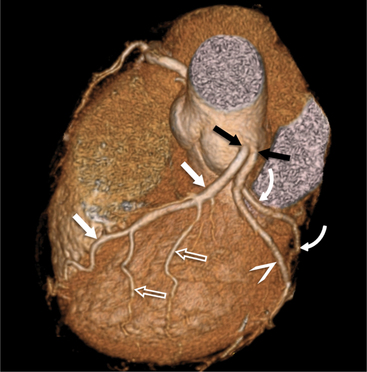
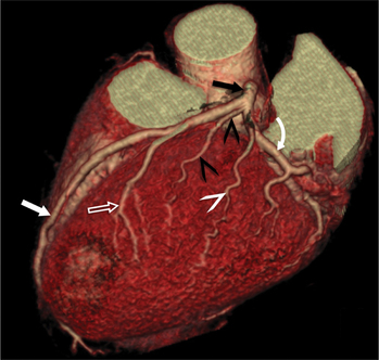
The LAD runs in the anterior interventricular groove and gives rise to septal perforators that perfuse the ventricular septum and to diagonal branches that supply the anterior LV wall. The distal LAD commonly wraps around the apex, where it may form collaterals to the PDA.
The LCX runs in the left atrioventricular groove and gives rise to obtuse marginal branches and posterolateral branches. If the PDA and PLV arise from the LCX, then the system is considered left dominant (Fig. 8-13). Codominance is present if both the RCA and the LCX provide a PDA branch.
CLINICAL ROLE OF CORONARY COMPUTED TOMOGRAPHY ANGIOGRAPHY
Detection of Coronary Artery Stenoses
Clinical applications of coronary CTA will critically depend on its accuracy for detection of significant stenoses. Numerous recent studies have assessed the accuracy of coronary CTA for stenosis detection in comparison to invasive, catheter-based coronary angiography. Using 40-slice CT, 64-slice CT, or dual-source CT, the sensitivity for the detection of coronary artery stenoses ranged from 86% to 100%, and the specificity ranged from 91% to 98%. Accuracy values are not uniform across all groups of patients. Several trials have convincingly shown that high heart rates and extensive calcification negatively influence accuracy. Usually, false-positive findings will occur if image quality is degraded and specificity will therefore be affected worst.
A recent meta-analysis has carefully analyzed and summarized the accuracy data that are available for coronary CTA with various generations of CT technology. The authors have demonstrated a significant increase in the sensitivity and specificity for stenosis detection as scanner technology progressed from 4-slice to 16-slice and 64-slice equipment (Table 8-1). For 64-slice CT, the analysis indicates a pooled sensitivity of 93% and specificity of 96% based on a per-segment analysis and sensitivity of 99% and specificity of 93% based on a per-patient analysis (363 patients total). These results confirm the high accuracy of coronary CTA for the detection of coronary artery stenoses, but it has to be taken into account that this applies to somewhat selected patients with stable sinus rhythm and usually a low heart rate, ability to cooperate and perform at least a 10-second breath hold, and absence of renal failure, previously implanted coronary stents, or previous bypass surgery. Also, studies were performed in single, experienced academic centers.

Rights were not granted to include this table in electronic media. Please refer to the printed book.
(From Vanhoenacker PK, Heijenbrok-Kal MH, Van Heste R, et al.: Diagnostic performance of multidetector CT angiography for assessment of coronary artery disease: meta-analysis, Radiology 44:419-428, 2007.)
Across all published studies, the negative predictive value of coronary CTA was uniformly high, ranging from 93% to 100%. This indicates that coronary CTA will be able to reliably rule out coronary artery stenoses in patients comparable to those that were included in these published trials if image quality is good. It has to be taken into account, however, that both the positive and negative predictive value will be influenced by the pretest likelihood of disease in the patient that is investigated—the negative predictive value will be lower for patients with a high pretest likelihood (which means that a negative result is more likely to be incorrect), whereas in patients with a low pretest likelihood, a positive result is more likely to represent a false-positive finding. As a consequence, the clinical use of coronary CTA—as that of any other diagnostic test—will substantially depend on the patient group that is investigated. In a recent publication by Meijboom and colleagues, the diagnostic accuracy of coronary CTA was analyzed in the context of the pretest likelihood of disease. It was clearly shown that the diagnostic value of CTA was highest in patients with a relatively low pretest likelihood of disease and lowest in those patients in whom the clinical presentation suggested a high likelihood that coronary stenoses would be present. Thus, clinical applications of CTA seem to be most beneficial whenever the clinical situation implies a relatively low pretest likelihood of coronary disease, but still requires further workup to rule out significant coronary stenoses. In clinical cardiology, this situation, both in the setting of stable symptoms and acute chest pain, is not infrequent.
Clinical Applications
Stents
Evaluation of coronary artery stents with coronary CTA remains challenging. It is possible to visualize stent lumen if the CT is of excellent quality, and if the contrast opacification is high, the noise level is low, motion and respiratory artifacts are absent, and the stent is large and in a proximal location. Such a combination of favorable conditions, however, is often not present.
IMAGING CORONARY ATHEROSCLEROTIC PLAQUE
Coronary Anomalies and Fistula
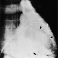
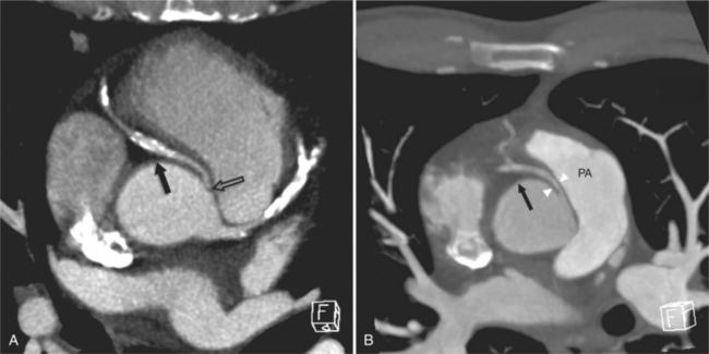
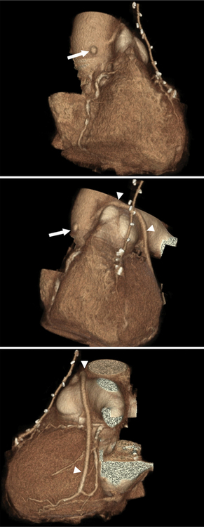
Coronary artery fistulas have a variable appearance on cross-sectional imaging or catheter angiography. The appearance depends on the number and site of abnormal connections between the coronary arterial system and a cardiac chamber or lower pressure vascular system. If the fistula connects to a cardiac chamber, such as the right ventricle, it is referred to as coronary-cameral (camera, Latin for “chamber”) fistula. General imaging features include one or multiple feeding vessels, which are usually dilated and tortuous. Often there is an aneurysmal dilatation just proximal to the abnormal connection with the lower pressure system. One of the more common types is a fistula between branches of the coronary arteries and the anterior surface of the PA. These may have one or multiple feeders from LAD branches, the conus branch of the RCA, or mediastinal branches of the aorta. Fistulas can occur with the right and left atria and ventricles or the coronary venous system. One extreme type of coronary fistula is if the entire left coronary artery system arises from the PA. This anomaly is referred to as anomalous left coronary artery arising from the pulmonary artery or ALCAPA, or as Bland-White-Garland syndrome. If the RCA has the abnormal origin, this entity is referred to as ARCAPA. In these anomalies, a steal phenomenon from normal coronary arteries via the abnormal vessel into the lower pressure PA develops, resulting in massive dilatation of the involved coronary arteries (Figures 8-14, 8-15, 8-16, 8-17).
CURRENT INDICATION FOR CORONARY COMPUTED TOMOGRAPHY ANGIOGRAPHY
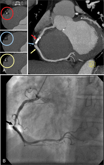
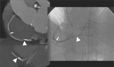
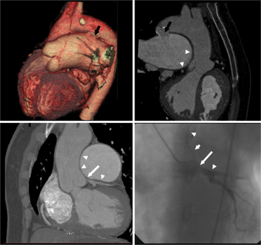
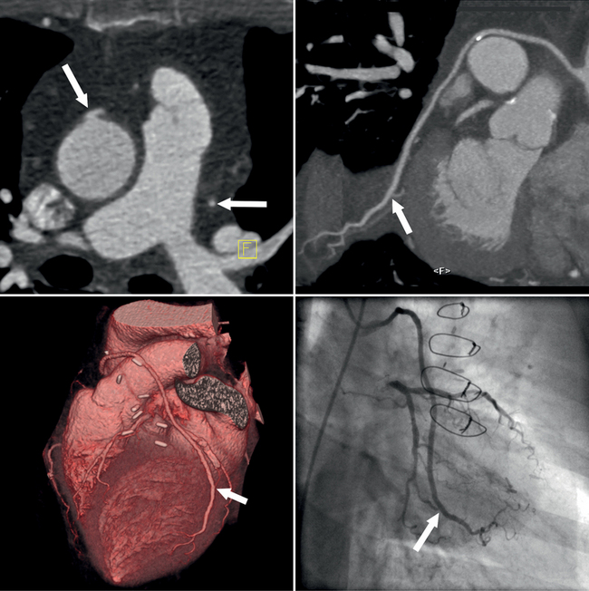
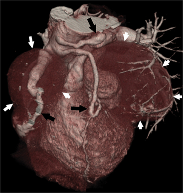
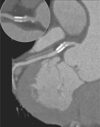
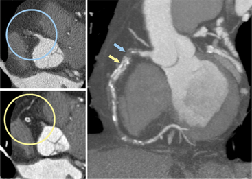
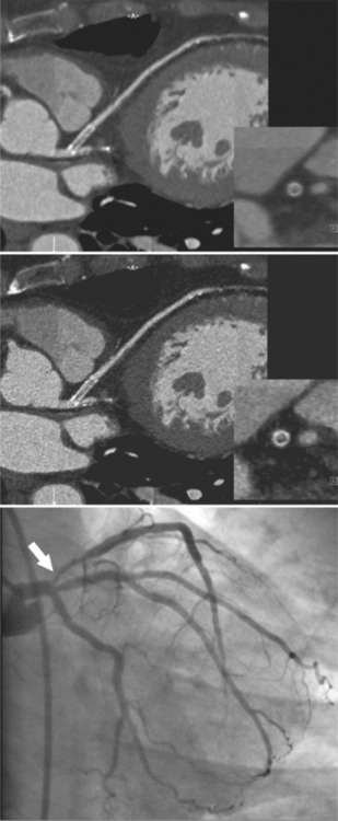
Coronary CTA is most appropriate to rule out significant coronary artery stenoses from atherosclerotic disease (Figures 8-18, 8-19, 8-20). However, CT is also very useful in the evaluation of aneurysms and bypass grafts (Figures 8-21, 8-22, 8-23, 8-24, 8-25, 8-26). Although the CT evaluation of stents should be discouraged if the stent diameter is 3.5 mm or less, in the presence of larger stents CT may determine the patency, occlusion, or in-stent restenosis (Figures 8-27, 8-28, 8-29).
Appropriateness Criteria
Recently published official documents that were developed jointly by multiple medical societies, including cardiology and radiology societies, offer recommendations as to the appropriate clinical use of coronary CTA (Table 8-2).
TABLE 8-2 “Appropriate” indications for computed tomography coronary angiography according to an expert consensus document
| Detection of CAD with prior test results—Evaluation of chest pain syndrome Uninterpretable or equivocal stress test result (exercise, perfusion, or stress echo) |
| Detection of CAD: symptomatic—Evaluation of chest pain syndrome Intermediate pretest probability of CAD, ECG uninterpretable or unable to exercise |
| Detection of CAD: symptomatic—Acute chest pain Intermediate pretest probability of CAD, no ECG changes, and serial enzymes negative |
| Evaluation of coronary arteries in patients with new-onset heart failure to assess etiology Evaluation of suspected coronary anomalies |
CAD, coronary artery disease; ECG, electrocardiogram.
(From Hendel RC, Patel MR, Kramer CM, et al: ACCF/ACR/SCCT/SCMR/ASNC/NASCI/SCAI/SIR 2006 appropriateness criteria for cardiac computed tomography and cardiac magnetic resonance imaging: a report of the American College of Cardiology Foundation Quality Strategic Directions Committee Appropriateness Criteria Working Group, American College of Radiology, Society of Cardiovascular Computed Tomography, Society for Cardiovascular Magnetic Resonance, American Society of Nuclear Cardiology, North American Society for Cardiac Imaging, Society for Cardiovascular Angiography and Interventions, and Society of Interventional Radiology, J Am Coll Cardiol 48:1475-1497, 2006).
Abbara S, Chow BJ, Pena AJ, et al. Assessment of left ventricular function with 16- and 64-slice multi-detector computed tomography. Eur J Radiol. 2008;67(3):481-486.
Abbara S, Cury RC, Nieman K, et al. Noninvasive evaluation of cardiac veins with 16-MDCT angiography. Am J Roentgenol. 2005;185(4):1001-1006.
Achenbach S. Cardiac CT: State of the art for the detection of coronary arterial stenosis. Journal of Cardiovascular Computed Tomography. 2007;1:3-20.
Achenbach S, Giesler T, Ropers D, et al. Detection of coronary artery stenoses by contrast-enhanced, retrospectively ECG-gated, multi-slice spiral CT. Circulation. 2001;103:2535-2538.
Achenbach S, Moselewski F, Ropers D, et al. Detection of calcified and noncalcified coronary atherosclerotic plaque by contrast-enhanced, submillimeter multidetector spiral computed tomography: a segment-based comparison with intravascular ultrasound. Circulation. 2004;109:14-17.
Achenbach S, Ropers D, Pohle FK, et al. Detection of coronary artery stenoses using multi-detector CT with 16 3 0.75 mm collimation and 375 ms rotation. Eur Heart J. 2005;26:1978-1986.
Achenbach S, Ulzheimer S, Baum U, et al. Noninvasive coronary angiography by retrospectively ECG-gated multislice spiral CT. Circulation. 2000;102:2823-2828.
Anders K, Baum U, Schmid M, et al. Coronary bypass graft (CABG) patency: assessment with high-resolution submillimeter 16-slice multidetector-row computed tomography (MDCT) versus coronary angiography. Eur J Radiol. 2006;57:336-344.
Andreini D, Pontone G, Pepi M, et al. Diagnostic accuracy of multidetector computed coronary tomography angiography in patients with dilated cardiomyopathy. J Am Coll Cardiol. 2007;49:2044-2050.
Becker CR, Knez A, Leber A, et al. Detection of coronary artery stenoses with multislice helical CT angiography. J Comp Assist Tomogr. 2002;26:250-255.
Becker CR, Knez A, Ohnesorge B, et al. Imaging of noncalcified coronary plaques using helical CT with retrospective ECG gating. Am J Roentgenol. 2000;175:423-424.
Cordeiro MA S, Miller JM, Schmidt A, et al. Noninvasive half-millimeter 32-detector-row CT angiography accurately excludes significant stenoses in patients with advanced coronary artery disease and high calcium scores. Heart. 2006;92:589-597.
Dodd JD, Ferencik M, Liberthson RR, et al. Congenital anomalies of coronary artery origin in adults: 64-MDCT appearance. Am J Roentgenol. 2007;188(2):W138-W146.
Dodd JD, Maree A, Palacios I, et al. Images in cardiovascular medicine. Left main coronary artery compression syndrome: evaluation with 64-slice cardiac multiâ-detector computed tomography. Circulation. 2007;115(1):e7-e8.
Datta J, White CS, Gilkeson RC, et al. Anomalous coronary arteries in adults: depiction at multi-detector row CT angiography. Radiology. 2005;235(3):812-818.
Deetjen AG, Conradi G, Möllmann S, et al. Diagnostic Value of the 16 detector row multislice spiral computed tomography for the detection of coronary artery stenosis in comparison to invasive angiography. Clin Cardiol. 2007;20:118-123.
Ehara M, Surmely JF, Kawai M, et al. Diagnostic accuracy of 64-slice computed tomography for detecting angiographically significant coronary artery stenosis in an unselected consecutive patient population. Circ J. 2007;70:564-571.
Einstein AJ, Henzlova MJ, Rajagopalan S. Estimating risk of cancer associated with radiation exposure from 64-slice computed tomography coronary angiography. JAMA. 2007;298:317-323.
Feuchtner GM, Schachner T, Bonatti J, et al. Diagnostic performance of 64-slice computed tomography in evaluation of coronary artery bypass grafts. Am J Roentgenol. 2007;189:574-580.
Fine JJ, Hopkins CB, Ruff N, et al. Comparison of accuracy of 64-slice cardiovascular computed tomography with coronary angiography in patients with suspected coronary artery disease. Am J Cardiol. 2006;97:173-174.
Garcia MJ, Lessick J, Hoffmann MH, et al. Accuracy of 16-row multidetector computed tomography for the assessment of coronary artery stenosis. JAMA. 2006;296:403-411.
Gaspar T, Halon DA, Lewis BS, et al. Diagnosis of coronary in-stent restenosis with multidetector row spiral computed tomography. J Am Coll Cardiol. 2005;46:1573-1579.
Gerber TC, Stratmann BP, Kuzo RS, et al. Effect of acquisition technique on radiation dose and image quality in multidetector row computed tomography coronary angiography with submillimeter collimation. Invest Radiol. 2005;40(8):556-563.
Ghershin E, Litmanovich D, Dragu R, et al. 16-MDCT coronary angiography versus invasive coronary angiography in acute chest pain syndrome: a blinded prospective study. Am J Roentgenol. 2006;186:177-184.
Ghostine S, Caussin C, Daoud B, et al. Non-invasive detection of coronary artery disease in patients with left bundle branch block using 64-slice computed tomography. J Am Coll Cardiol. 2006;48:1935-1937.
Giesler T, Baum U, Ropers D, et al. Noninvasive visualization of coronary arteries using contrast-enhanced multidetector CT: influence of heart rate on image quality and stenosis detection. Am J Roentgenol. 2002;179:911-916.
Gilard M, Cornily JC, Pennec PY, et al. Accuracy of multislice computed tomography in the preoperative assessment of coronary disease in patients with aortic valve stenosis. J Am Coll Cardiol. 2006;47:2020-2024.
Gilard M, Cornily JC, Pennec PY, et al. Assessment of coronary artery stents by 16 slice computed tomography. Heart. 2006;92:58-61.
Halliburton SS, Abbara S. Practical tips and tricks in cardiovascular computed tomography: Patient preparation for optimization of cardiovascular CT data acquisition. Journal of Cardiovascular Computed Tomography. 2007;01(1):62-65.
Halon DA, Gaspar T, Adawi S, et al. Uses and limitations of 40 slice multi-detector row spiral computed tomography for diagnosing coronary lesions in unselected patients referred for routine invasive coronary angiography. Cardiology. 2007;108:200-209.
Hausleiter J, Meyer T, Hadamitzky M, et al. Radiation dose estimates from cardiac multislice computed tomography in daily practice. Circulation. 2006;113:1305-1310.
Herzog C, Arning-Erb M, Zangos S, et al. Multi-detector row CT coronary angiography: Influence of reconstruction technique and heart rate on image quality. Radiology. 2006;238:75-86.
Herzog C, Zwerner PL, Doll JR, et al. Significant coronary artery stenosis: Comparison on per-patient and per-vessel or per-segment basis at 64-section CT angiography. Radiology. 2007;244:112-120.
Hoffmann MH, Shi H, Manzke R, Schmid FT, et al. Noninvasive coronary angiography with 16-detector row CT: effect of heart rate. Radiology. 2005;234:86-97.
Hoffmann MH K, Shi H, Schmitz BL, et al. Noninvasive coronary angiography with multislice computed tomography. JAMA. 2005;293:2471-2478.
Hoffmann U, Moselewski F, Cury RC, et al. Predictive value of 16-slice multidetector spiral computed tomography to detect significant obstructive coronary artery disease in patients at high risk for coronary disease. Patient versus segment-based analysis. Circulation. 2004;110:2638-2643.
Hoffmann U, Nagurney JT, Moselewski F, et al. Coronary multidetector computed tomography in the assessment of patients with acute chest pain. Circulation. 2006;114:2251-2260.
Hollander JA, Litt HI, Chase M, et al. Computed tomography coronary angiography for rapid disposition of low-risk emergency department patients with chest pain syndromes. Acad Emerg Med. 2007;14:112-116.
Knez A, Becker CR, Leber A, et al. Usefulness of multislice spiral computed tomography angiography for determination of coronary artery stenoses. Am J Cardiol. 2001;88:1191-1194.
Kopp AF, Schroeder S, Kuettner A, et al. Non-invasive coronary angiography with high resolution multidetector-row computed tomography. Results in 102 patients. Eur Heart J. 2002;23:1714-1725.
Kuettner A, Trabold T, Schroeder S, et al. Noninvasive detection of coronary lesions using 16-detector multislice spiral computed tomography technology. Initial clinical results. J Am Coll Cardiol. 2004;44:1230-1237.
Leber AW, Johnson T, Becker A, et al. Diagnostic accuracy of dual-source multi-slice CT-coronary angiography in patients with an intermediate pretest likelihood for coronary artery disease. Eur Heart J. 2007;28(19):2354-2360.
Leber AW, Knez A, von Ziegler F, et al. Quantification of obstructive and nonobstructive coronary lesions by 64-slice computed tomography. A comparative study with quantitative coronary angiography and intravascular ultrasound. J Am Coll Cardiol. 2005;46:147-154.
Lee SI, Miller JC, Abbara S, et al. Coronary CT angiography. J Am Coll Radiol. 2006;3(7):560-564.
Lim MC L, Wong TW, Yaneza LO, et al. Non-invasive detection of significant coronary artery disease with multi-section computed tomography angiography in patients with suspected coronary artery disease. Clin Radiol. 2006;61:174-180.
Maintz D, Seifarth H, Raupach R, et al. 64-slice multidetector coronary CT angiography: in vitro evaluation of 68 different stents. Eur Radiol. 2006;16(4):818-826.
Manghat NE, Morgan-Hughes GJ, Broadley AJ, et al. 16-detector row computed tomographic coronary angiography in patients undergoing evaluation for aortic valve replacement: comparison with catheter angiography. Clin Radiol. 2006;61:749-757.
Martuscelli E, Romagnoli A, D’Eliseo A, et al. Accuracy of thin-slice computed tomography in the detection of coronary stenoses. Eur Heart J. 2004;25:1043-1048.
Meijboom WB, Mollet NR, Van Mieghem CA, et al. 64-slice computed tomography coronary angiography in patients with non-ST elevation acute coronary syndrome. Heart. 2007;93(11):1386-1392.
Meijboom WB, Mollet NR, von Mieghem CA G, et al. Pre-operative computed tomography coronary angiography to detect significant coronary artery disease in patients referred for cardiac valve surgery. J Am Coll Cardiol. 2006;48:1658-1665.
Meyer TS, Martinoff S, Hadamitzky M, et al. Improved noninvasive assessment of coronary artery bypass grafts with 64-slice computed tomographic angiography in an unselected patient population. J Am Coll Cardiol. 2007;49:946-950.
Mollet NR, Cademartiri F, Nieman K, et al. Multislice spiral computed tomography coronary angiography in patients with stable angina pectoris. J Am Coll Cardiol. 2004;43:2265-2270.
Mollet NR, Cademartiri F, van Mieghem C, et al. Adjunctive value of CT coronary angiography in the diagnostic work-up of patients with typical angina pectoris. Eur Heart J. 2007;28(15):1787-1789.
Mühlenbruch G, Seyfarth T, Soo CS, et al. Diagnostic value of 64-slice multi-detector row cardiac CTA in symptomatic patients. Eur Radiol. 2007;17:603-609.
Nieman K, Cademartiri F, Lemos PA, et al. Reliable noninvasive coronary angiography with fast submillimeter multislice spiral computed tomography. Circulation. 2002;106:2051-2054.
Nieman K, Oudkerk M, Rensing BJ, et al. Coronary angiography with multi-slice computed tomography. Lancet. 2001;357:599-603.
Nieman K, Pattynama PM T, Rensing BJ, et al. Evaluation of patients after coronary artery bypass surgery: CT angiographic assessment of grafts and coronary arteries. Radiology. 2003;229:749-756.
Nikolaou K, Knez A, Rist C, et al. Accuracy of 64-MDCT in the diagnosis of ischemic heart disease. Am J Roentgenol. 2006;187:111-117.
Ohnesorge B, Flohr T, Becker C, et al. Cardiac imaging by means of electrocardiographically gated multisection spiral CT: initial experience. Radiology. 2000;217:564-571.
Oncel D, Oncel G, Karaca M. Coronary stent patency and in-stent restenosis: determination with 64-section multidetector CT coronary angiography—initial experience. Radiology. 2007;242:403-409.
Onuma Y, Tanabe K, Chihara R, et al. Evaluation of coronary artery bypass grafts and native coronary arteries using 64-slice multidetector computed tomography. Am Heart J. 2007;154:519-526.
Raff GJ, Gallagher MJ, O Neill WW, et al. Diagnostic accuracy of noninvasive angiography using 64-slice spiral computed tomography. J Am Coll Cardiol. 2005;46:552-557.
Reant P, Brunot S, Lafitte S, et al. Predictive value of noninvasive coronary angiography with multidetector computed tomography to detect significant coronary stenosis before valve surgery. Am J Cardiol. 2006;97:1506-1510.
Rist C, von Ziegler F, Nikolaou K, et al. Assessment of coronary artery stent patency and restenosis using 64-slice computed tomography. Acad Radiol. 2006;13:1465-1473.
Ropers D, Pohe FK, Kuettner A, et al. Diagnostic accuracy of noninvasive coronary angiography in patients after bypass surgery using 64-slice spiral computed tomography with 330-ms gantry rotation. Circulation. 2006;114(22):2334-2341.
Ropers D, Rixe J, Anders K, et al. Usefulness of multidetector row computed tomography with 64 × 0.6 mm collimation and 330-ms rotation for the noninvasive detection of significant coronary artery stenoses. Am J Cardiol. 2006;97:343-348.
Rubinshtein R, Halon DA, Gaspar T, et al. Usefulness of 64-slice cardiac computed tomographic angiography for diagnosing acute coronary syndromes and predicting clinical outcome in emergency department patients with chest pain of uncertain origin. Circulation. 2007;115:1762-1768.
Rubinshtein R, Halon DA, Gaspar T, et al. Usefulness of 64-slice multidetector computed tomography in diagnostic triage of patients with chest pain and negative or nondiagnostic exercise treadmill test result. Am J Cardiol. 2007;99:925-929.
Salm LP, Bax JJ, Jukema JW, et al. Comprehensive assessment of patients after coronary artery bypass grafting by 16-detector-row computed tomography. Am Heart J. 2005;150:775-781.
Scheffel H, Alkadhi H, Plass A, et al. Accuracy of dual-source CT coronary angiography: first experience in a high pre-test probability population without heart rate control. Eur Radiol. 2006;16:2739-2747.
Schlosser T, Konorza T, Hunold P, et al. Noninvasive visualization of coronary artery bypass grafts using 16-detector row computed tomography. J Am Coll Cardiol. 2004;44(6):1224-1229.
Schlosser T, Mohrs OK, Magedanz A, et al. Noninvasive coronary angiography using 64-detector-row computed tomography in patients with a low to moderate pretest probability of significant coronary artery disease. Acta Radiol. 2007;48:300-307.
Schuijf JD, Bax JJ, Jukema JW, et al. Feasibility of assessment of coronary stent patency using 16-slice computed tomography. Am J Cardiol. 2004;94(4):427-430.
Schuijf JD, Pundzuite G, Jukema JJ, et al. Diagnostic accuracy of 64-slice multislice computed tomography in the noninvasive evaluation of significant coronary artery disease. Am J Cardiol. 2006;98:145-148.
Shabestari AA, Abdi S, Akhlaghpoor S, et al. Diagnostic performance of 64-channel multislice computed tomography in assessment of significant coronary artery disease in symptomatic subjects. Am J Cardiol. 2007;99:1656-1661.
Schoepf UJ, Zwerner PL, Savino G, et al. Coronary CT angiography. Radiology. 2007;244:48-63.
Van Mieghem CA, Cademartiri F, Mollet NR, et al. Multislice spiral computed tomography for the evaluation of stent patency after left main coronary artery stenting: a comparison with conventional coronary angiography and intravascular ultrasound. Circulation. 2006;114:645-653.
Vanhoenacker PK, Heijenbrok-Kal MH, Van Heste R, et al. Diagnostic performance of multidetector CT angiography for assessment of coronary artery disease: meta-analysis. Radiology. 2007;44:419-428.
Watkins MW, Hesse B, Green CE, et al. Detection of coronary artery stenosis using 40-channel computed tomography with multisegment reconstruction. Am J Cardiol. 2007;99:175-181.