Chapter 32 Complications of Catheter Ablation of Cardiac Arrhythmias
Reported rates of major complications following contemporary catheter ablation procedures vary by as much as five- to eightfold between various types of ablation procedures, ranging from 0.8% for supraventricular tachycardia (SVT), 3.4% for idiopathic ventricular tachycardia (VT), 5.2% for atrial fibrillation (AF), and 6.0% for VT associated with structural heart disease. Death is a rare complication of catheter ablation, occurring in 0.11% to 0.30% of patients with regular SVT, and in 0.31% of those with VT. Transseptal catheterization appears to be the cause of death in 0.2% of procedures.1
Local Vascular Complications
Complications at the catheter insertion sites are among the most common problems observed following catheter ablation procedures, estimated to occur in about 2% to 6% of procedures, and can cause significant morbidity. Local vascular complications are higher among females, older adults, obese patients, and those with preexisting peripheral vascular disease. Additionally, the risk is related to the type of procedure performed (right or left heart catheterization), the size and number of sheaths and catheters used during the procedure, as well as the associated periprocedural use of anticoagulant or antiplatelet agents.2 The rates of complications related to the site of vascular access are higher following catheter ablation of AF (1.8%) and VT in patients with structural heart disease (0.7% to 4.7%) compared with ablation of SVT (0.4%).1
Bleeding is the most common vascular complication. This can simply result in a local hematoma of little clinical significance. Vascular laceration can cause large hematomas in the groin and thigh. Acute bleeding generally can be controlled with prolonged manual compression. Groin hematomas usually resolve in 1 to 2 weeks if ongoing bleeding is stopped. Large hematomas can require blood transfusion, but surgical repair is rarely required. Arteriovenous fistulas and pseudoaneurysms need to be excluded in the setting of large or continually expanding hematomas. Retroperitoneal hematomas are often the result of arterial puncture above the inguinal ligament, allowing bleeding and hematoma to extend to the retroperitoneal space. Retroperitoneal hematomas should be suspected in the setting of a marked drop in hematocrit or unexplained hypotension or flank pain. Abdominal computed tomography (CT) scanning or ultrasound is required to confirm the diagnosis. Retroperitoneal bleeds are generally managed conservatively (bed rest, blood transfusion). Catheter or surgical interventions, however, can occasionally be required.3
Femoral arteriovenous fistulas commonly result when bleeding from the arterial puncture tracks into the adjacent venous puncture. Arteriovenous fistulas are more likely to arise when arterial and venous punctures are performed on the same side or when arterial puncture is performed below the common femoral artery, where several superficial branches of the femoral vein overlie the femoral artery. Diagnosis is made on examination with the finding of a pulsatile mass with a continuous “to and fro” bruit and confirmed by ultrasound. Many of the iatrogenic arteriovenous fistulas are small and close spontaneously within 1 year, but ultrasound-guided compression or surgical repair can be necessary. Because cardiac volume overload and limb damage are highly unlikely with persistent arteriovenous fistulas, conservative management for at least 1 year is reasonable.2
Cardiac Perforation
Incidence
Previous studies reported the incidence of cardiac perforation with catheter-based interventions as follows: 0.8% for all procedures, 1.5% to 4.7% for valvuloplasty, 0.5% to 0.8% for angioplasty-atherectomy, 0.01% for diagnostic catheterization, 0.1% to 0.2% for electrophysiological (EP) studies, 0.2% for SVT ablation, 0.4% to 2.7% for VT ablation, and 0.5% to 4.0% for left atrial (LA) ablation.1,4,5
The incidence of procedure-related cardiac tamponade increases with the increasing number of catheter ablation procedures for the treatment of AF, which typically involves one or more atrial septal punctures, extensive intracardiac catheter manipulation and ablation within the thin-walled LA, and the need for high levels of systemic anticoagulation during the procedure.2,6
Mechanism
Cardiac perforation can be caused by mechanical trauma secondary to catheter manipulation, myocardial tissue rupture due to radiofrequency (RF) ablation, or inadvertent injury during atrial septal puncture. Extensive catheter manipulation, especially in areas with thin walls such as the LA roof, right ventricular (RV) free wall, RV outflow tract (RVOT), RV apex, and atrial appendages, can cause mechanical tear of the chamber wall. Cardiac perforation can also occur away from the area of mapping and ablation, usually caused by penetration of an unattended RV catheter in the setting of rapid and vigorous heart action because of high-dose isoproterenol infusion. Inadvertent puncture of the right atrial (RA) free wall or lateral LA wall can occur during transseptal catheterization. High RF power output, especially when using large- or irrigated-tip ablation catheters, can increase the risk of cardiac perforation. An audible pop associated with an abrupt rise in impedance is heard in many patients who develop tamponade. Popping occurs because of tissue boiling causing myocardial rupture, and is increased by irrigated-tip ablation, high tissue-catheter interface flow, poor or unstable tissue contact, and high catheter tip temperature.2,6
Detection
Prompt recognition and management of cardiac perforation are critical to prevent the development of cardiac tamponade and potentially life-threatening hemodynamic collapse. Although the presentation often is dramatic with abrupt hypotension, it can be insidious with a more gradual fall in blood pressure. The use of an arterial line that provides continuous blood pressure monitoring can help detect early hemodynamic compromise. Sinus tachycardia is common in the setting of cardiac tamponade that gradually develops. Nonetheless, the absence of tachycardia does not exclude cardiac tamponade; in fact sinus bradycardia can develop secondary to a vagal reflex in the setting of a rapidly developing cardiac tamponade. Any chest pain that persists beyond the completion of an ablation lesion, especially if associated with hypotension and diaphoresis, should alert the operator to the possible development of pericardial effusion.2,6–8
Assessment of the cardiac silhouette fluoroscopically can provide the first clue, especially if a similar assessment was made at baseline. Decreased excursion of the lateral heart border on fluoroscopy in the left anterior oblique (LAO) projection, indicating accumulating pericardial effusion, usually can be seen well before a drop in blood pressure and prior to progression to cardiac tamponade. Some operators obtain a baseline LAO cine image at the onset of a procedure to serve as a reference for comparison during the procedure, followed by intermittent evaluation of the same fluoroscopic projection during the procedure.2,6–8
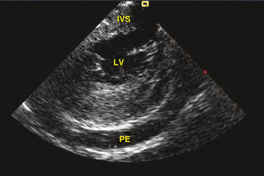
Transthoracic echocardiography is the most definitive method for confirming the development of pericardial effusion. Intracardiac echocardiography (ICE), commonly used to guide transseptal puncture for LA procedures, also can facilitate the early detection of pericardial effusions before the emergence of tamponade physiology. Most of the pericardial space is not visualized from the RA imaging venue used to visualize the interatrial septum, and limited catheter rotation is usually required. Advancing the ICE catheter into the RV and rotating the transducer against the interventricular septum can readily identify pericardial effusions (Fig. 32-1).
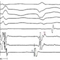
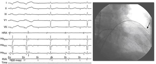
Perforation without tamponade may occur during placement of diagnostic catheters or while accessing the LA by transseptal catheterization; detection at this time can prevent progression to tamponade but requires a high index of suspicion. Several clues should alert the operator to the possibility of cardiac perforation, including a ventricular catheter that reaches the edge of the cardiac silhouette, high pacing thresholds at sites despite normal electrograms and apparent good tissue contact on fluoroscopy, a right bundle branch block (RBBB) complex during “RV” pacing, and a catheter tip position discordant from where it should be (i.e., an RV catheter too far leftward with intended RV apical location; Fig. 32-2). With atrial septal puncture for accessing the left heart chambers, the aorta can be inadvertently entered; if only the needle enters the aorta and this is recognized before advancing the dilator and sheath, the needle can be withdrawn and the patient monitored for stability of vital signs and with echocardiography. The procedure can be continued if there is no accumulation of pericardial fluid after 15 to 30 minutes of monitoring. If the dilator and sheath have been advanced into the aortic root before the error is recognized, it is imperative that the sheath not be removed immediately, as this can result in immediate and perhaps irretrievable hemodynamic collapse due to intractable bleeding into the pericardial space.
Management
The management of pericardial effusion is largely determined by its relative size and hemodynamic effect. Trivial pericardial effusions, if recognized early during the procedure, should be monitored continuously but do not warrant termination of the procedure. For larger effusions, the procedure should be terminated and anticoagulation, if administered, should be reversed. Protamine is used to reverse the effects of heparin, and activated factor VII, fresh frozen plasma, and vitamin K can be used in patients with therapeutic anticoagulation with warfarin. Intravenous fluids, vasopressors, and transfusion of blood products can be required, depending on the extent of the effusion and the severity of hemodynamic decompensation. Intravenous atropine can be of value in patients with increased vagal tone.3,9
Although pericardiocentesis typically is required for large pericardial effusions, smaller effusions manifesting signs of cardiac tamponade, or both, and can effectively restore hemodynamic function, it carries the potential risk of cardiac chamber laceration, inadvertent puncture of the RV, pneumothorax, and infection. In a subset of patients (especially older female patients with a small to moderate amount of pericardial effusion who are not anticoagulated), a conservative approach incorporating administration of intravenous fluids and vasopressors to address the hemodynamic consequences of cardiac tamponade was found in a recent report a reasonable initial strategy and could obviate the need for emergency pericardiocentesis.2,7
Pericardiocentesis should be performed promptly when indicated, because there is usually a narrow therapeutic time window for intervention before critical hemodynamic compromise ensues. The procedure can be performed under fluoroscopic guidance (Video 22)  . Echocardiography can also be used to guide pericardiocentesis (Video 23
  ). When echocardiography is not readily available, fluoroscopy is usually adequate to guide a safe procedure, and reliance on transthoracic echocardiography should not lead to unnecessary delay in diagnosis or therapy. The technique of percutaneous pericardiocentesis is discussed in Chapter 27. In most patients, an indwelling catheter is required for a short interval after initial drainage to confirm that the bleeding has stopped and that no effusion is reaccumulating. In the event of persistence or rapid reaccumulation of the effusion, exploration by thoracic surgery can be required. Up to 13.3% of LA perforations during AF ablation require surgical closure. Autotransfusion of blood removed from the pericardial space can be of value in patients with persistent bleeding, and is best done using an autologous blood recovery system, because direct autotransfusion can result in a systemic inflammatory response.3,6,9
Early pericarditis after cardiac perforation is common. In one report, 53.3% of such patients had persistent chest pain after effusion evacuation and removal of the pericardial catheter suggestive of pericardial inflammation. Nonsteroidal antiinflammatory agents are adequate in most patients. Additionally, intrapericardial steroids (triamcinolone, 20 mg) can help reduce pericardial inflammation. Subacute reaccumulation of pericardial fluid suggestive of postcardiac injury syndrome or inflammatory pericarditis can also occur, requiring repeat pericardiocentesis.3,9
Thromboembolism
Systemic thromboembolism can complicate EP procedures in the left side of the heart. The rate of thromboembolic events is 0.4% to 2.1% for AF ablation and up to 2.8% for ablation of VT originating in the left ventricle (LV).1,4,10 In patients undergoing AF ablation, history of a prior cerebrovascular event is the most potent individual risk factor for post-ablation cerebrovascular events and is associated with a ninefold increased risk of periprocedural stroke. Additionally, the incidence of periprocedural stroke increases in a step-wise fashion with an increasing CHADS2 score (congestive heart failure, hypertension, age >75 years, diabetes, and previous stroke/transient ischemic attack).10
Mechanism
Potential sources of emboli include thrombus formation on high-profile wires, catheters, and sheaths inserted in the LA or LV, char formation at the tip of the ablation catheter or at the site of ablation, thrombi or air passing through a patent foramen ovale or transseptal puncture, and dislodgment of a preexistent LA or LV thrombus by catheter manipulation. Additionally, new LA appendage thrombi may develop in patients with persistent AF after planned or inadvertent conversion to sinus rhythm, especially in the setting of insufficient levels of anticoagulation before, during, or after ablation. Furthermore, endocardial disruption from the ablation lesions can potentially become a nidus for thrombus formation. Also, aortic atheroembolism can occur during retrograde transaortic LV access for ablation of VTs or atrioventricular (AV) bypass tracts (BTs), and it tends to be associated with difficulty in manipulation of catheters within a severely diseased aorta.10
Thromboembolic events typically occur within 24 hours of the ablation procedure, with the high-risk period extending for the first 2 weeks following ablation. Cerebral thromboembolism is most common, but emboli can also involve the coronary, abdominal, or peripheral vascular circulations. Although silent cerebral thromboembolism has been reported, its incidence and clinical significance are unknown.11
Prevention
Prevention remains the best strategy in minimizing cerebrovascular events during left heart mapping and ablation, and this may be achieved by the following: (1) preprocedural transthoracic or transesophageal echocardiography (TEE) in patients with AF as well as those with ischemic VT with LV dysfunction; (2) aggressive intraprocedural anticoagulation, including early heparin administration (once vascular access is obtained), followed by continuous infusion to maintain the activated clotting time at greater than 300 seconds; (3) meticulous attention to sheath management, including constant infusion of heparinized saline and air filters; (4) minimizing char formation during lesion creation by regulating power delivery to prevent abrupt impedance rise; and (5) using ICE during AF ablation for early detection of intracardiac thrombi and accelerated bubble formation consistent with endocardial tissue disruption with RF application. Open-irrigation RF ablation or cryoablation, compared with standard 4- or 8-mm solid tip or closed irrigation electrodes, can potentially decrease the formation of char and thrombus at the tip of the ablation catheter.10 Administration of large doses of protamine on completion of the ablation procedure to reverse heparin abruptly can potentially promote thrombogenesis and warrants further evaluation to confirm its safety. Continuation of warfarin at a therapeutic level at the time of AF ablation can potentially be a better alternative to strategies that use bridging with heparin or enoxaparin, as it eliminates a period of inadequate anticoagulation immediately following the ablation procedure, a critical period for thromboembolic risk because of the inflammation and irritation inherently associated with ablation.12,13
Air Embolism
Vascular air embolism is a potentially life-threatening event that can occur during left and right heart procedures. Because many cases of venous air embolism go unnoticed, the true incidence of this complication is unknown. Air embolism has been reported in the interventional radiology literature at an incidence of 0.13%.2,3,9
Mechanism
Paradoxical air embolization into the arterial circulation can occur through direct passage of air into the arterial system via anomalous structures such as an atrial or ventricular septal defect, a patent foramen ovale, or pulmonary arterial-venous malformations. Direct arterial air embolism is caused by the introduction of air into the LA via the transseptal sheath as well as via long vascular sheaths occasionally used for catheter stabilization during transaortic mapping and ablation in the LV.3,9
Clinical Presentation
Most cases of venous air embolism are subclinical and do not result in untoward outcomes, and even when symptomatic, they go unrecognized because of the nonspecific nature of clinical presentation that can mimic other cardiac, pulmonary, and neurological dysfunctions. Therefore, a high index of suspicion is necessary to establish the diagnosis.3
The outcome of venous air embolism is directly related to the amount of air and the rate at which it enters the vein. Spontaneously breathing patients can experience more serious consequences than those under controlled positive-pressure ventilation because they generate negative intrathoracic pressure during the respiratory cycle, facilitating air entrainment. Awake patients typically manifest shortness of breath, continuous coughing, chest pain, and a sense of “impending doom.” Jugular venous distention, hypotension, tachycardia, and electrocardiographic (ECG) signs of right heart strain (ST-T wave abnormalities) can be observed. Severe cases are characterized by cardiovascular collapse.3,9
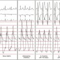
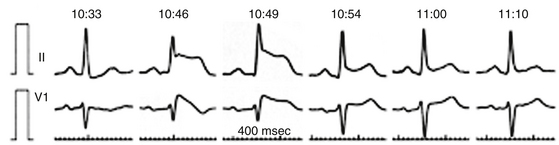
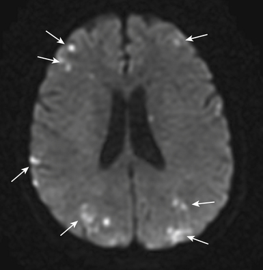
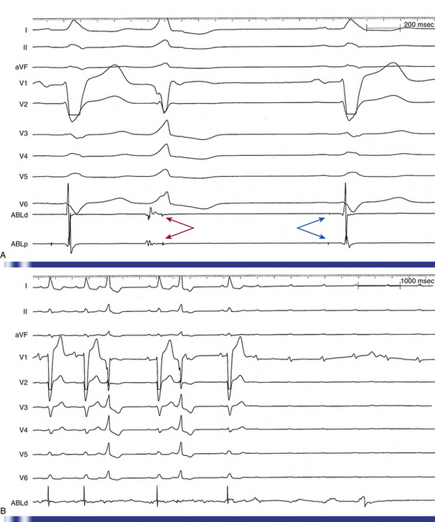
Arterial air emboli can distribute to almost any organ and can have devastating clinical sequelae. Direct cerebral air embolism can be associated with altered mental status, seizures, and focal neurological signs. A common presentation of air embolism during LA mapping and ablation is acute inferior ischemia, heart block, or both (Fig. 32-3). This reflects preferential downstream migration of air emboli into the right coronary artery.
Detection
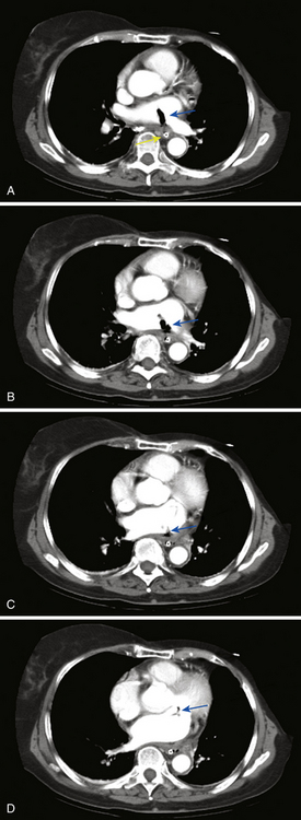
Routine diagnostic modalities to identify air embolism in the terminal arterial circulations lack sensitivity, and diagnosis is typically based on the appropriate clinical scenario, with possible air identified in cardiac chambers. Air in the RV or pulmonary artery can be visualized on fluoroscopy as well as transthoracic echocardiography. TEE is currently the most sensitive monitoring device for venous air embolism. Prompt CT or magnetic resonance (MR) imaging obtained before the intravascular air is absorbed may show multiple serpiginous hypodensities representing air in the cerebral vasculature, with or without acute infarction, but imaging later in the course of the disease shows diffuse acute infarcts (Fig. 32-4).3,9
Prevention
The optimal management of air embolism is prevention. Careful sheath management, including constant infusion of heparinized saline and air filters, should be observed. Although air can be introduced through the infusion line, it can also occur with suction when catheters are removed. Therefore, whenever catheters are removed, they need to be withdrawn slowly to minimize suction effects and the fluid column within the sheath should be aspirated simultaneously. The sheath should then be aspirated and irrigated to ascertain that neither air nor blood has collected in the sheath.3 Importantly, the entire volume of the sheath should be aspirated after initial deployment as well as after each time a catheter is removed and reinserted, in order to ensure that a continuous column of fluid is present in the sheath and disallowing the possibility of trapped air that could otherwise be introduced when a catheter is advanced through the sheath. Testing to ascertain the sheath’s capacity prior to insertion is a good practice.
Management
Initially, it is essential to take all measures necessary to prevent further air embolization. For venous air embolism, placing the patient in the left lateral decubitus and Trendelenburg position helps air remain in the RA, where it will not contribute to an “air lock” in the RVOT. Additionally, direct extraction of air from the venous circulation if localized in the RA or RV can be attempted by aspiration from a central venous or pulmonary artery catheter. Air aspiration should be performed with the patient supine or in a Trendelenburg position while holding his or her breath at the end of inspiration or during a Valsalva maneuver.14
Administration of intravenous fluids and vasopressors can be necessary for hemodynamic support. Supplemental 100% oxygen therapy can reduce the size of the air embolus by increasing the rate of nitrogen absorption from air bubbles. Because gas bubbles are not buoyant enough to counteract arterial blood flow, these measures are more suitable for treating venous and RV air emboli.14
When cerebral air embolism is suspected, it is important to maximize cerebral perfusion by administration of fluids and supplemental oxygen. Hyperbaric oxygen therapy is regarded as the treatment of choice in patients with cerebral air embolism and prompt transfer to a hyperbaric oxygen therapy center should be considered. When started within a few hours, hyperbaric oxygen therapy can potentially compress the existing bubbles, speed resolution of bubbles by establishing a high diffusion gradient, improve oxygenation of ischemic tissues, and reduce endothelial thromboinflammatory injury.3,11,14
Coronary Artery Injuries
The incidence of coronary artery injuries during ablation procedures is extremely low despite the close proximity of coronary arteries to common sites of ablation. The low incidence is likely due, at least in part, to the high-velocity blood flow within the epicardial coronary arteries, allowing these vessels to act as a heat sink; substantive heating of vascular endothelium is prevented by heat dissipation in the coronary blood flow (convective cooling), even when the catheter is positioned close to the vessel. However, high RF power delivery in small hearts, such as in pediatric patients, or in direct contact with the vessel can potentially cause coronary arterial injury.15,16 Additionally, the rarity of coronary artery injury can be due to underrecognition, because its clinical presentation (e.g., chest discomfort and elevation in cardiac troponin levels) can easily be misdiagnosed as pericardial irritation, myocardial injury secondary to RF ablation, or both.
Mechanism
The potential for acute coronary artery occlusion is a significant risk consideration with catheter ablation within the aortic cusps. Damage to the coronary arteries can result from catheter manipulation and ablation in the aortic root, secondary to RF energy delivery in close proximity to the ostium of the right or left coronary artery, as well as inadvertent catheter engagement of the left main coronary artery when ablating in the left coronary cusp.17,18
It is also important to recognize the potential risk of coronary artery damage when ablating in the RVOT and pulmonary artery. The right coronary artery is typically 4 to 5 mm away from the proximal part of the RVOT near the free wall, and is separated by a variable amount of fat. Additionally, the cephalocaudal separation of the pulmonic and aortic valves results in close proximity of the pulmonic valve to the origin of the right coronary artery, and the left main coronary artery lies in immediate posterior proximity to the subvalvular RVOT near the pulmonic valve as well as the supravalvular pulmonary artery.17,18
Because of the proximity of the right coronary artery to the cavotricuspid isthmus and the left circumflex artery to the lateral mitral annulus, coronary artery injury can potentially occur during ablation at mitral or tricuspid annuli.15 Transient inferior ST segment elevation and acute occlusion of the right coronary artery have been reported following ablation of the cavotricuspid isthmus, and left circumflex artery injury has been reported following ablation of left-sided AV BTs. Also, late stenosis of the right coronary artery has been observed in children with Ebstein anomaly of the tricuspid valve who undergo ablation of a right-sided AV BT.19
Percutaneous epicardial ablation probably poses a greater risk of coronary artery injury, severe spasm, or both, whereby the large epicardial coronary arteries can be in direct contact with the ablation catheter and movement of the ablation catheter in the pericardial space can occur during ablation endangering adjacent coronary arteries. The coronary sinus (CS) and its branches are also in close relation to the distal circumflex and the posterolateral branches of the right coronary artery, and ablation within the coronary venous system (for AV BTs, lateral mitral isthmus, and VT) can cause coronary injuries.5,15
RF injury to coronary arteries can cause acute thrombosis or damage to the arterial wall. Arterial injury is inversely proportional to vessel diameter; there is little evidence of injury when vessel diameter exceeds 0.5 to 1.0 mm.15
Clinical Presentation
Coronary arterial injury generally presents with acute coronary occlusion or spasm at the time of ablation associated with chest pain and ST elevation; nonetheless, delayed presentations can also occur.15
Importantly, RF ablation frequently (in 25% to 100% of cases) causes significant elevations in cardiac troponin levels that are not related to coronary arterial injury, with mean peak levels of 0.13 to 6 ng/mL for troponin I, and 0.20 to 2.41 ng/mL for troponin T. In contrast to acute coronary syndromes, troponin elevations observed following RF ablation typically peak early (2 to 8 hours versus 18 to 24 hours) and normalize early.20 The levels of troponin elevation correlate with the number of RF lesions applied, the site of lesions (ventricular more than atrial more than annular), and the approach to the left side (transaortic more than transseptal). Ablation of focal lesions (atrioventricular nodal reentrant tachycardia [AVNRT], atrioventricular reentrant tachycardia [AVRT]) causes less frequent (in 25% to 88% of cases) elevation of troponin levels as compared with linear lesion ablation (typical and atypical atrial flutter [AFL], AF, and VT) where all patients are expected to have an increase in troponin levels. The prognostic significance of asymptomatic elevations of troponin I remains unclear.20
Prevention
Several precautions are important to avoid injury to coronary arteries during percutaneous epicardial ablation, ablation via the coronary venous system, and ablation in the coronary cusps. Prior to ablation near or within a branch of the CS or in the pericardial space, direct visualization of the relation between the ablation site and adjacent coronary arteries must be obtained, usually by coronary angiography performed with the ablation catheter on the target site. An absolute safe distance between the ablation site and epicardial artery has not been defined; nonetheless, a distance of at least 5 mm between the ablation catheter and an epicardial artery is commonly accepted. It is also important to ensure that the catheter is not touching the vessel at any point of the cardiac cycle during angiography. Cryoablation appears to have less risk of coronary injury in animal models, but can still create occlusion and intimal damage when in close proximity, particularly to small vessels.5
When ablation in the aortic cusp is planned, it is preferable to insert a 5 Fr pigtail catheter into the aortic root and obtain aortic root angiography to visualize the aortic root and the ostia of the right and left coronary arteries.18 Selective angiography of the coronary arteries also can be performed with the ablation catheter positioned at the desired location so as to assess the anatomical relationships between these structures and the location of the ablation catheter. If the origin of VT is in the left coronary cusp, it is preferable to cannulate the left main coronary artery with a 5 Fr left Judkins catheter, which serves as a marker and for protection of the left main coronary artery in case of ablation catheter dislodgment during RF application. Alternatively, a combination of electroanatomical mapping and ICE imaging can be used to confirm anatomical location, catheter tip position and contact, and distance to coronary vasculature and to monitor RF delivery.17
To avoid injuring the coronary arteries during ablation of arrhythmias arising from the coronary cusps, it is preferable to start RF energy delivery at a low power output (15 W) and then increase to no more than 30 W to achieve a target temperature of approximately 50°C. Additionally, ablation should also be performed during continuous fluoroscopy to observe for catheter dislodgment, and energy delivery should be discontinued in case of even minimal dislodgment from the site showing the best mapping findings. RF application should also be stopped if the repetitive or sustained VT cannot be terminated after 10 seconds. Coronary angiography is often performed immediately after the ablation procedure to exclude coronary artery spasm, dissection, or thrombus.18
Iatrogenic Cardiac Arrhythmias
Atrioventricular Block
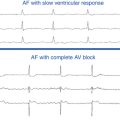
AV block is the most important complication of AVNRT ablation. AV block occurs in about 0.2% to 0.8% of slow pathway ablation using the posterior approach, generally occurs during RF delivery or within the first 24 hours postablation, and is almost always preceded by junctional ectopy with VA block. The level of block is usually in the atrioventricular node (AVN). Predictors of AV block include proximity of the anatomical ablation site to the compact AVN, occurrence of fast junctional tachycardia (cycle length <350 milliseconds) during RF application, occurrence of junctional rhythm with VA block, the number of RF applications (related to the amount of tissue damage), and significant worsening of anterograde AV conduction during the ablation procedure. The anterior approach for AVNRT ablation is associated with a higher risk of inadvertent complete AV block (approximately 10%, but ranging from 2% to 20%).21 During ablation of AVNRT, careful monitoring of AV conduction during RF application and prompt discontinuation of energy delivery on evidence of AV block are the keys to minimize the incidence of AV block. RF delivery should be immediately discontinued when the following occur: (1) the impedance rises suddenly (>10 Ω); (2) the PR interval (during normal sinus rhythm [NSR] or atrial pacing) prolongs; (3) AV block develops; (4) retrograde conduction block is observed during junctional ectopy; or (5) fast junctional tachycardia (tachycardia cycle length <350 milliseconds) occurs, which can herald imminent heart block.
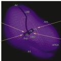
AV block can also occur when ablating along the interventricular septum in the close vicinity of the compact AVN or His bundle (HB), including ablation of superoparaseptal and midseptal AV BTs or ATs as well as para-Hisian VTs. Additionally, because the penetrating HB lies at the membranous septum formed in part by the commissure between the right coronary and noncoronary cusps, ablation of VTs originating in this region can potentially damage the HB (Fig. 32-5).
When a His potential is detectable at the ablation catheter location, titrated RF energy output and RF application for a short duration should be used, coupled with overdrive atrial pacing to monitor AV conduction in case accelerated junctional rhythm occurs. Alternatively, cryoablation can be used in this region with its slightly better safety margin for AV conduction.22,23
Macroreentrant Atrial Tachycardias
Whereas the occurrence of new arrhythmias following focal RF ablation has not been a clinical problem, linear ablation lesions, if incomplete, can promote reentry propagating through the gaps in the ablation lines. Even when conduction block across the ablation lines is verified, the ablation lines commonly performed in the LA for ablation of AF can still facilitate reentry by providing conduction obstacles and protected isthmuses with adjacent anatomical structures in the atrium.24,25 In fact, LA macroreentry is a relatively common complication of catheter ablation of AF, occurring in up to 50% of cases. The incidence of ATs seems to be lower following segmental ostial pulmonary vein (PV) isolation (<5%) compared with circumferential PV isolation, and much higher following circumferential or linear LA ablation (>30%). Targeting complex fractionated atrial electrograms without linear lesions or PV isolation is associated with a moderate risk (8.3%) for post-ablation ATs. Following stepwise approaches of catheter ablation incorporating extensive lesions in the LA and RA to terminate persistent AF, ATs can be observed in more than 50% of patients.26–28 Although ATs can occur at variable time intervals after AF ablation procedures, the most common timing appears to be 1 to 2 months postablation.29,30
Valvular Damage
Damage to the mitral valve can result from entanglement of the ablation catheter within the mitral valve apparatus during transaortic or transseptal ablation procedures, but serious damage is unlikely. The risk of valvular damage (occasionally requiring thoracic surgery and valve replacement) is higher following entrapment of catheters with multiple splines or circular mapping catheters in the valvular apparatus (e.g., during AF ablation), which can be potentially difficult to free. Forcible traction of the catheter should be avoided as it can potentially damage the valve and ultimately lead to mitral valve replacement. To prevent injury to the papillary muscles or chordae tendineae, prior to pulling on the catheter, one may consider instead advancing the catheter toward the LV apex. Advancing the sheath over the catheter and withdrawing the catheter into the sheath followed by withdrawal of the whole assembly can facilitate the effort further. When gentle manipulation and moderate traction are unsuccessful, removing the catheter by thoracic surgery may be preferable; in this way the valve can potentially be spared significant damage.3,31
Phrenic Nerve Injury
The intrathoracic course of the right phrenic nerve, especially as it approximates the superior vena cava (SVC) and RA (and not infrequently the right superior PV), is the principal reason for susceptibility to nerve damage from endocardial ablation. Injury to the right phrenic nerve has typically been reported during sinus node modification or ablation of ATs in the RA free wall, SVC, or right superior PV. Right phrenic nerve injury has become more frequent with the increasing number of AF ablation procedures that involve electrical isolation of the SVC as well as ablation around the right superior PV, especially when balloon ablation catheters are used. The reported incidence of phrenic nerve injury secondary to AF ablation varies from 0% to 0.48%.32,33
The left phrenic nerve descends behind the left brachiocephalic vein and passes over the aortic arch, pulmonary trunk, and then with the pericardium over the LA appendage. From there it descends along the pericardium over the LV and frequently passes laterally over the obtuse margin of the LV, close to the lateral vein and the left marginal artery and, in only a small percentage of cases, close to the left main coronary artery and great cardiac vein. Left phrenic nerve injury can occur during AF or AT ablation in the region of the proximal LA appendage roof, during ablation of left posterolateral BTs, as well as during percutaneous epicardial ablation adjacent to the lateral LV wall.34,35
Clinical Presentation
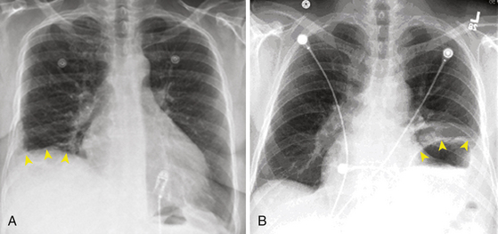
Phrenic nerve injury can be asymptomatic in about one-third of cases. The most frequent symptom is dyspnea. Other symptoms or clinical findings are cough or hiccup during ablation and the development of postablation pneumonia or pleural effusion. In asymptomatic patients, the diagnosis is made on the routine chest x-ray (Fig. 32-6) with hemidiaphragm paresis or paralysis (hemidiaphragm elevation with paradoxical movement). There is no active treatment known to aid phrenic nerve healing. Complete or partial recovery of diaphragmatic function can be observed in 66% and 17% of patients, respectively, sometimes not realized until several weeks or even months later.36
Prevention
In areas at high risk of phrenic nerve injury (RA free wall, posteroseptal part of the SVC, inferoanterior aspect of the right PV ostium, and proximal LA appendage roof) that require ablation, high-output (10 mA) pacing should be performed before energy delivery. The ability to pace the phrenic nerve should prompt attempting to find a slightly different site or, if this is not possible, applying RF energy at low power and/or for short duration. This technique can be combined with electroanatomical mapping of the RA, SVC, LA, and right PVs to reconstruct the anatomical course of the right phrenic nerve. Even when the phrenic nerve cannot be paced, intermittent fluoroscopic visualization of the ipsilateral diaphragm movement should be performed during RF application at high-risk sites, and RF delivery should be terminated if diaphragmatic excursion decreases.
Recently, diaphragmatic electromyography has been used to monitor phrenic nerve integrity during ablation. A progressive decline in compound motor action potential amplitude heralded phrenic nerve palsy, with a 30% decrease yielding the best predictive value, preceding hemidiaphragmatic paralysis by about 30 seconds. To record right diaphragmatic compound motor action potentials, two standard surface electrodes are connected to a central computerized electrophysiology workstation. The recording electrode is placed on the thorax 5 cm superior to the tip of the xiphoid process and the reference electrode is positioned along the right costal margin with a 16-cm interelectrode distance. Diaphragmatic bipolar electromyographic signals are recorded during continuous pacing of the right phrenic nerve, using a catheter in the SVC. The clinical application of this approach to prevent phrenic nerve palsy induced by cryoballoon ablation of the right superior PV is still in its preliminary stages, and further evaluation is required to validate and optimize this approach.37,38
During percutaneous epicardial ablation, proximity to the phrenic nerve can be detected by high-output pacing (typically at >10 mA) to detect diaphragmatic stimulation on fluoroscopy, allowing its course to be marked on a three-dimensional (3-D) map.39 The nerve can branch over the LV, so simply noting sites at which phrenic nerve capture occurs does not necessarily delineate the course of all branches. It is important to recognize that detection by phrenic nerve capture is prevented by the use of paralytic agents during general anesthesia. However, these drugs are typically used during induction of anesthesia and their effects have dissipated by the time ablation is being performed. Catheter ablation should be avoided at sites adjacent to the phrenic nerve. Alternatively, moving the nerve away from the myocardium by injection of air into the pericardium or placement of a balloon catheter between the ablation target site and nerve can allow safe RF ablation. Alternative energy sources such as cryoenergy have been used to prevent phrenic nerve injury. Cryomapping uses temporary phrenic nerve injury to determine when to avoid full cryoablation. However, data on the success of cryoablation in the pericardial space are limited.34,35
Pulmonary Vein Stenosis
Incidence
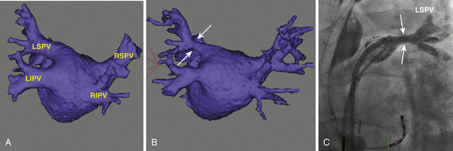
PV stenosis is one of the most serious complications of AF ablation and has been reported with a wide range of incidence (0% to 42%), mainly because of different ablation strategies and differing methodology for estimating postablation PV ostia. The severity of PV stenosis is generally categorized as mild (<50%), moderate (50% to 70%), or severe (>70%). When moderate and mild lesions are included, the overall rate is as high as 15.5% (Fig. 32-7). However, the rate of severe PV stenosis has fallen to as low as 1.0% to 1.4% with increasing experience and improvements in technique, such as performing ablation outside the PVs and the use of ICE. Late progression of PV stenosis to severe stenosis or even complete occlusion can occur in up to 27% of patients (Fig. 32-8), particularly in the smaller PVs. Of note, stenosis seems to be more common in the left-sided PVs.11
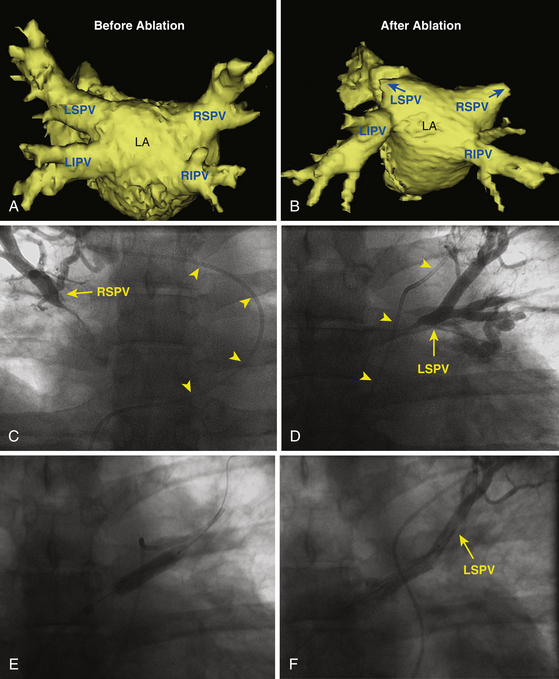
Circumferential LA ablation, with ablation limited to atrial tissue outside the PV orifice, seems to have lower rates of PV stenosis, whereas focal ablation inside the PV has a higher risk. Moreover, with PV isolation techniques, the use of an individual encircling lesion set that requires RF ablation between the ipsilateral PVs carries a higher risk of PV stenosis. With the focal ablation approach, PV stenosis can occur at a rate up to 33% to 42%. Although this represents an overestimation of the problem because increased TEE flow velocity was used to establish the diagnosis, it remains a major concern. With PV isolation techniques, the incidence of severe PV stenosis is approximately 1% to 5%. MR and spiral CT scanning have shown that although current PV isolation techniques are associated with minimal reduction of the PV ostial diameter, stenosis exceeding 50% can occur in up to 18% of cases, whereas very severe stenosis (>90%) is found in up to 2% of cases. Following circumferential LA ablation, the prevalence of PV stenosis likely ranges between 2% and 7%. In one report, a detectable reduction in PV diameter was present in 38% of PVs; however, moderate and severe PV stenosis was observed in 3.2% and 0.6% of PVs, respectively.3,9
Mechanism
The mechanism of the development of PV stenosis remains unclear. Acute reduction of PV diameter (by approximately 30%) has been demonstrated during ablation. It was initially speculated that these changes are caused by edema and spasm. Thermal injury, induced by RF, has recently been shown to produce Ca2+-mediated irreversible tissue contracture occurring with the production of most if not all RF lesions, and therefore almost certainly contributes to stenosis. It is well known that thermal injury produces denaturation of extracellular proteins, especially collagen. Thermally induced collagen shrinkage has been well documented in animal and human studies. When near-circumferential lesions are produced within the tubular confines of the PVs, the consequences can be easily demonstrated as PV contracture. Thus, PV stenosis likely results from a combination of endothelial disruption with platelet activation and later neointimal proliferation, reversible edema, collagen denaturation, and shrinkage and thermal contracture. The occurrence and degree of PV stenosis correlate with the amount of energy delivered and lesion extension. The high incidence of mild PV stenosis likely reflects PV reverse remodeling rather than pathological PV stenosis. This hypothesis is based on the observation that all the mild PV stenoses were concentric rather than eccentric.3,9
When severe stenosis or occlusion of a PV develops suddenly, gradual decline and then cessation of the arterial flow to the affected lung segment are observed. This is caused by a decline in the arteriovenous gradient as well as compression by the developing tissue edema. As a consequence, the involved alveoli are affected by the resulting ischemia and surrounding edema, leading to atelectasis, infarction, or susceptibility to infections. With the resulting alterations in pulmonary hemodynamics, redistribution of blood flow occurs with the opening of vascular channels or neovascularization in which tissue hypoxia is known to play a role. Hence, the venous drainage of the affected segment becomes mainly dependent on the ipsilateral veins draining the healthy lobes. If the ipsilateral vein(s) is also stenosed, the impedance to the pulmonary flow increases, adding to the hemodynamic burden. Symptoms attributable to PV stenosis are typically not seen unless the perfusion of the affected lobe falls below 20% or the perfusion of the entire lung on the affected side falls below 25%.40
Clinical Presentation
PV stenosis after ablation is frequently asymptomatic, especially when a mild or moderate degree of PV stenosis is present or a single vein is involved. Severe PV stenosis can be associated with various respiratory symptoms that frequently mimic more common lung diseases, such as asthma, pneumonia, lung cancer, and pulmonary embolism. A high degree of suspicion is necessary to avoid performing misleading diagnostic procedures and to allow proper and prompt management. The onset of symptoms is usually several months after ablation. The initial manifestation is generally dyspnea on exertion, which typically evolves over the course of 1 to 3 months. Persistent cough is a common symptom. Pleuritic chest pain is a late symptom, and hemoptysis is uncommon. Both pleuritic chest pain and hemoptysis are likely related to complete vessel or branch occlusion.3,9
Detection
To date, it remains unclear which is the best and most cost-effective noninvasive modality for detecting PV stenosis after ablation. TEE and CT scanning are most commonly used (Videos 24 and 25  ); however, no single imaging modality has been able to assess all relevant aspects of PV stenosis. Therefore, complementary methods are used (see Fig. 32-7). Although many investigators recommend routine follow-up CT or MR imaging for detection of asymptomatic PV stenosis 3 to 4 months after ablation of AF, it is unknown whether early diagnosis and treatment of asymptomatic PV stenosis provide any long-term advantage to the patient.40 Nevertheless, it is recommended that follow-up PV imaging be performed to screen for PV stenosis during the initial experience of an AF ablation technique for quality control purposes.3,9
Spiral CT and MR imaging of the PVs are readily available and can reveal the correct diagnosis; they are probably the most helpful in identifying the location and extent of the stenosis (see Fig. 32-7). However, the sensitivity and specificity of these imaging modalities need to be studied further. Of note, the diagnosis of PV occlusion cannot be made reliably using CT or MR imaging, and pulmonary artery wedge angiography is the only method for confirming the diagnosis.41
TEE provides adequate visualization of the superior PVs, but imaging of the right and left inferior PVs is inconsistent. Hence, TEE is not typically used as a first-line imaging study for routine screening. Nonetheless, TEE provides additional functional data regarding the significance of PV stenosis.40 On TEE, PV stenosis is usually indicated by an increased maximal PV Doppler flow velocity or by the presence of turbulence and deformity of the flow signal, as defined by a minimal flow between systolic and diastolic peak flow of 60% of the mean of both peaks. ICE allows straightforward imaging of all PVs and provides a good view into the first 1 to 3 cm of the vein. Color flow contrast imaging is also useful for identifying the location of the orifice of the most tightly stenotic vessels.
Prevention
The best way to manage PV stenosis is to avoid it. PV stenosis is independently related to RF lesion location, size, and distribution and to baseline PV diameter . The prevalence of this complication has decreased because of various factors, including abandonment of in-vein ablation at the site of the AF focus, limiting ablation to the extraostial portion of the PV or PV antrum, use of advanced imaging techniques to guide catheter placement and RF application, reduction in target ablation temperature and energy output, and increased operator experience.11
Management
PV intervention is recommended in symptomatic patients. PV stenting appears to be associated with a lower restenosis rate compared with angioplasty (Video 26).  42 For asymptomatic patients with severe PV stenosis, some investigators have also suggested interventional therapy because lesions can progress and eventually lead to total occlusion, precluding dilation and potentially resulting in hemodynamic compromise (see Fig. 32-8).11 Others have proposed regular clinical follow-up and intervention considered only when symptoms develop. However, it is important to understand that patients can become symptomatic only after the long-term sequelae of PV occlusion become manifest, at which time intervention may not be technically feasible or, even when successful, may not be associated with significant improvement in perfusion of the affected lung segments. It is also important to consider the age, functional capacity, and associated comorbidities as well as anatomical and technical factors pertaining to the stenotic vein when making a decision regarding interventional treatment in asymptomatic patients.11
TEE or ICE can facilitate accurate stent placement by reliably identifying the orifice of the tightly stenotic vein. Unfortunately, both in-stent and in-segment restenosis can recur in up to 61% of patients, and repeat intervention is warranted in symptomatic patients. Stenosis within the body of the stent is likely caused by neointimal hyperplasia and fibrosis. Out-of-stent restenosis is usually observed at bifurcation points beyond the stent into the vessel, also suggesting the progression of PV pathology, despite stent placement. There is no experience to date with the use of drug-eluting stents in this setting, but such a high restenosis rate makes a strong case for the investigation of those devices and larger diameter stents.11
Atrioesophageal Fistula
Incidence
The true incidence of atrioesophageal fistula after catheter ablation is unknown, but has been estimated to be between 0.03% and 0.2%, although underreporting is likely.43,44 Despite its rarity, atrioesophageal fistula remains a devastating complication associated with high mortality, accounting for 15.6% of cases with fatal outcome (the second leading cause of death post AF ablation, following cardiac tamponade).45
On the other hand, esophageal mucosal changes consistent with thermal injury have been reported in up to 47% of the patients following AF ablation, and esophageal ulcerations confirmed by esophagogastroscopy or capsule endoscopy can be observed in 14% to 18%.46,47
Mechanism
The precise mechanism of atrioesophageal fistula formation has not yet been determined. Proposed potential mechanisms include direct thermal injury of the esophageal wall in immediate proximity to the posterior LA wall, thermal injury of the arterial blood supply to the esophagus, and mechanical injury to the esophagus during periprocedural TEE as a contributing or predisposing factor.3
The esophagus is located at the center of the posterior mediastinum and runs in close proximity to the posterior LA wall for about 5 cm of its course. In that region, the esophagus is separated from the LA only by the pericardial sac (the oblique sinus), which insinuates itself between the openings of the right and left PVs. The LA posterior wall thickness is 2 to 4 mm and the thickness of the esophageal wall is 2 to 3 mm in cross section at the LA-esophageal area of contact. During RF catheter ablation, lesion depth, extension, and volume are related to the design of the ablation electrode and RF power delivered. Theoretically, esophageal damage can occur, even during LA ablation using a standard 4-mm-tip ablation catheter. However, cooled and large-tip ablation catheters induce extended lesions. Thus, delivering high-power RF applications on the LA posterior wall between the left and right PVs can potentially deeply damage the esophagus, resulting in atrioesophageal fistula formation.48,49
The risk of esophageal injury likely is enhanced by increasing the magnitude and duration of local tissue heating (i.e., the total ablation energy delivered to cardiac tissue near the esophagus), which is related to catheter tip size, contact pressure, catheter orientation, and power output and duration. In fact, all reported cases of atrioesophageal fistulas have in common attempts to perform deep RF lesions on the LA posterior wall. Additionally, ablation strategies incorporating extensive ablation in the LA posterior wall and the type of AF (persistent more than paroxysmal AF, possibly due to the additional linear ablation lesions) have been associated with an increased rate of esophageal ulcerations. A short LA-to-esophagus distance, the use of nasogastric tubes, and general anesthesia are other potential risk factors for esophageal injury during RF ablation.49,50
Cryoballoon ablation commonly causes significant decreases in esophageal temperature, especially during cryoablation of the inferior PVs, resulting in esophageal ulcerations. Although no instances of atrioesophageal fistula formation after cryoballoon PV isolation have yet been reported, the total number of cryoballoon ablation cases performed is relatively small to reliably detect this rare complication. Furthermore, esophageal ulcerations have been observed following cryoballoon ablation at rates (17% of patients) similar to those seen with RF ablation. Although there is no definitive proof that esophageal ulcer formation is predictive of fistulas, it is reasonable to assume that esophageal ulcerations may represent the first step on the way to atrioesophageal fistula. Therefore, until further experience indicates otherwise, cryoballoon ablation should not be considered completely safe in regard to atrioesophageal fistula formation.51
Excessive esophageal heating, esophageal ulcerations, and atrioesophageal fistula formation have been observed post PV isolation using high-intensity focused ultrasound (HIFU). In a recent study, elevated esophageal temperature prompting cessation of HIFU energy delivery occurred in 9% of PVs. Despite use of the safety algorithm, the occurrence of esophageal thermal damage and lethal atrioesophageal fistula could not be prevented, occurring in 1 of 28 patients. This safety concern argues against the clinical use of HIFU in its current iteration for PV isolation.52
Clinical Presentation
Leukocytosis is the earliest and most sensitive laboratory marker. Thoracic CT or MR imaging is the most valuable diagnostic examination (Fig. 32-9, Video 27  ). The dramatic neurological complications occur with a delay of at least a few hours after the first symptoms. Endoscopy is a diagnostic modality that should be avoided because insufflation of the esophagus with air can result in a devastating cerebrovascular accident and death secondary to a large air embolus. Immediate surgery (within a few hours after the first symptoms) can potentially prevent neurological complications and possibly result in a high survival rate, without residue. Delay of treatment seems to have devastating results.3
Prevention
Various strategies may be used to avoid the development of an atrioesophageal fistula, including the following: (1) assessment of esophageal position before and during ablation; (2) avoiding ablation in the vicinity of the esophagus; (3) mechanical displacement of the esophagus; (4) monitoring of the esophageal temperature during energy delivery; and (5) reduction of ablation energy power output and duration at sites close to the esophagus. However, because of the rarity of this complication, it remains unproven whether the use of these approaches lowers or eliminates the risk of esophageal perforation or fistula formation, and the optimal technique has not yet been determined. Therefore, it appears prudent to apply a combination of these preventive techniques during AF ablation. These strategies are discussed in detail in Chapter 11.48–50,53–55
Radiation Exposure
Radiation exposures during the different interventional procedures are highly variable. Cardiac catheterizations generally expose patients to an average dose of 250 rad (2.5 Gy). Percutaneous coronary interventions are particularly dangerous (average dose, 640 rad [6.4 Gy]) because radiation is focused only on those vessels with stenosis. Although these represent standard exposure estimates, interventional procedures are highly variable.56 In one report, only 1 of 15 patients undergoing AF ablation reached a peak skin dose of 2 Gy, despite prolonged fluoroscopy durations (up to 99 minutes). This finding is striking and speaks to the effectiveness of the systems that use several technologies to reduce radiation exposure, such as last image hold, pulsed fluoroscopy, and additional filters.57
Clinical Presentation
In EP procedures, the patient tissue receiving the greatest radiation dose is the skin area of the back at the entrance point of the x-ray beam, and skin injuries are well-recognized complications for catheter ablation procedures. The threshold for transient erythema and epilation is 2 to 3 Gy, for acute skin injury is 2 to 8 Gy, and for chronic radiation injury is 10 Gy.56 Obese patients, those with preexisting health conditions such as collagen vascular disease, diabetes mellitus, or ataxia telangiectasia, and those who received a high radiation dose from a previous procedure, can be at a greater risk for radiation skin damage.
Acute radiation injury (characterized by erythema with vesiculation, erosion, and pain) usually starts within days after exposure and persists up to several weeks (Fig. 32-10). Chronic radiation injury manifests months to years after exposure and presents clinically as permanent erythema, dermal atrophy, and ulceration.
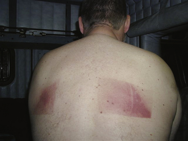
Acute radiation-induced skin injury can be misdiagnosed as contact dermatitis, viral or bacterial infection, or a spider bite, and a high index of suspicion is required. Fluoroscopy-induced injuries affect an area congruent to the entrance of the x-ray beam that typically has well-defined borders (see Fig. 32-10), which occur when the beam is not moved or resized during prolonged fluoroscopy over one site. It is important to alert patients who had undergone prolonged procedures or known to have received a high skin radiation dose to examine him- or herself about 2 to 3 weeks after the procedure to look for skin changes and to contact the interventionalist if any are observed.
The estimated lifetime risk of a fatal malignancy after AF ablation using a modern low-frame pulsed fluoroscopy system is relatively low (0.15% for women and 0.21% for men in one report) and is higher than, although within the range of, previously reported risk to result from the ablation of standard types of supraventricular arrhythmias (0.03% to 0.26%). It has been estimated that for every 60 minutes of fluoroscopy, the mean total lifetime excess risk of a fatal malignancy is 0.03% to 0.065%.
Prevention
Increasing availability and familiarity with 3-D mapping systems should significantly reduce fluoroscopy time and the need for biplane fluoroscopy. The use of remote navigation systems also is likely to reduce fluoroscopy exposure of the patient and operator.57 Additionally, judicious and intermittent use of fluoroscopy, that is, keeping the x-rays on for only a few seconds at a time, long enough to view the current catheter position, can reduce total fluoroscopic times considerably. The presence of grids in x-ray systems primarily increases the contrast and hence the image quality; however, they increase the dose to the patient and staff by a factor of two or more, and removal of the grid can help reduce the dose of radiation. Additionally, periodically rotating the fluoroscope at different angles helps spread the total radiation dose over a broader area of the patient’s skin so that no single region receives the entire dose. Other methods include adjustment of beam quality, using pulsed fluoroscopy, inserting appropriate metal filters (aluminum, copper, or other materials) into the beam at the collimator, and minimizing geometric magnification by keeping the image receptor close to the patient and the source away.
1. Bohnen M., Stevenson W.G., Tedrow U.B., et al. Incidence and predictors of major complications from contemporary catheter ablation to treat cardiac arrhythmias. Heart Rhythm. 2011;8:1661-1666.
2. Doppalapudi H., Yamada T., Kay N. Complications during catheter ablation of atrial fibrillation: identification and prevention. Heart Rhythm. 2009;6:S18-S25.
3. Calkins H., Brugada J., Packer D.L., et al. HRS/EHRA/ECAS Expert Consensus Statement on Catheter and Surgical Ablation of Atrial Fibrillation: recommendations for personnel, policy, procedures and follow-up. A report of the Heart Rhythm Society (HRS) Task Force on Catheter and Surgical Ablation of Atrial Fibrillation. Heart Rhythm. 2007;4:816-861.
4. Natale A., Raviele A., Al-Ahmad A., et al. Venice Chart International Consensus document on ventricular tachycardia/ventricular fibrillation ablation. J Cardiovasc Electrophysiol. 2010;21:339-379.
5. Aliot E.M., Stevenson W.G., Mendral-Garrote J.M., et al. EHRA/HRS Expert Consensus on Catheter Ablation of Ventricular Arrhythmias: developed in a partnership with the European Heart Rhythm Association (EHRA), a Registered Branch of the European Society of Cardiology (ESC), and the Heart Rhythm Society (HRS); in collaboration with the American College of Cardiology (ACC) and the American Heart Association (AHA). Heart Rhythm. 2009;6:886-933.
6. McElderry H.T., Yamada T. How to diagnose and treat cardiac tamponade in the electrophysiology laboratory. Heart Rhythm. 2009;6:1531-1535.
7. Kim R.J., Siouffi S., Silberstein T.A., et al. Management and clinical outcomes of acute cardiac tamponade complicating electrophysiologic procedures: a single-center case series. Pacing Clin Electrophysiol. 2010;33:667-674.
8. Latchamsetty R., Gautam S., Bhakta D., et al. Management and outcomes of cardiac tamponade during atrial fibrillation ablation in the presence of therapeutic anticoagulation with warfarin. Heart Rhythm. 2011;8:805-808.
9. Dixit S., Marchlinski F.E. How to recognize, manage, and prevent complications during atrial fibrillation ablation. Heart Rhythm. 2007;4:108-115.
10. Scherr D., Sharma K., Dalal D., et al. Incidence and predictors of periprocedural cerebrovascular accident in patients undergoing catheter ablation of atrial fibrillation. J Cardiovasc Electrophysiol. 2009;20:1357-1363.
11. Barrett C.D., Di Biase L., Natale A. How to identify and treat patient with pulmonary vein stenosis post atrial fibrillation ablation. Curr Opin Cardiol. 2009;24:42-49.
12. Gautam S., John R.M., Stevenson W.G., et al. Effect of therapeutic INR on activated clotting times, heparin dosage, and bleeding risk during ablation of atrial fibrillation. J Cardiovasc Electrophysiol. 2011;22:248-254.
13. Hussein A.A., Martin D.O., Saliba W., et al. Radiofrequency ablation of atrial fibrillation under therapeutic international normalized ratio: a safe and efficacious periprocedural anticoagulation strategy. Heart Rhythm. 2009;6:1425-1429.
14. Mirski M.A., Lele A.V., Fitzsimmons L., Toung T.J. Diagnosis and treatment of vascular air embolism. Anesthesiology. 2007;106:164-177.
15. Roberts-Thomson K.C., Steven D., Seiler J., et al. Coronary artery injury due to catheter ablation in adults: presentations and outcomes. Circulation. 2009;120:1465-1473.
16. Cesario D., Boyle N., Shivumar K. Lesion forming technologies for catheter ablation. In: Zipes D.P., Jalife J., editors. Cardiac electrophysiology: from cell to bedside. ed 5. Philadelphia: WB Saunders; 2009:1051-1058.
17. Callans D.J. Catheter ablation of idiopathic ventricular tachycardia arising from the aortic root. J Cardiovasc Electrophysiol. 2009;20:969-972.
18. Tabatabaei N., Asirvatham S.J. Supravalvular arrhythmia: identifying and ablating the substrate. Circ Arrhythm Electrophysiol. 2009;2:316-326.
19. Mykytsey A., Kehoe R., Bharati S., et al. Right coronary artery occlusion during RF ablation of typical atrial flutter. J Cardiovasc Electrophysiol. 2010;21:818-821.
20. Alaiti M.A., Maroo A., Edel T.B. Troponin levels after cardiac electrophysiology procedures: review of the literature. Pacing Clin Electrophysiol. 2009;32:800-810.
21. Estner H.L., Ndrepepa G., Dong J., et al. Acute and long-term results of slow pathway ablation in patients with atrioventricular nodal reentrant tachycardia—an analysis of the predictive factors for arrhythmia recurrence. Pacing Clin Electrophysiol. 2005;28:102-110.
22. Steven D., Rostock T., Hoffmann B.A., et al. Favorable outcome using an abbreviated procedure for catheter ablation of AVNRT: results from a prospective randomized trial. J Cardiovasc Electrophysiol. 2009;20:522-525.
23. Opel A., Murray S., Kamath N., et al. Cryoablation versus radiofrequency ablation for treatment of atrioventricular nodal reentrant tachycardia: cryoablation with 6-mm-tip catheters is still less effective than radiofrequency ablation. Heart Rhythm. 2010;7:340-343.
24. Sawhney N., Anousheh R., Chen W., Feld G.K. Circumferential pulmonary vein ablation with additional linear ablation results in an increased incidence of left atrial flutter compared with segmental pulmonary vein isolation as an initial approach to ablation of paroxysmal atrial fibrillation. Circ Arrhythm Electrophysiol. 2010;3:243-248.
25. Schmidt M., Daccarett M., Segerson N., et al. Atrial flutter ablation in inducible patients during pulmonary vein atrium isolation: a randomized comparison. Pacing Clin Electrophysiol. 2008;31:1592-1597.
26. Matsuo S., Lim K.T., Haissaguerre M. Ablation of chronic atrial fibrillation. Heart Rhythm. 2007;4:1461-1463.
27. Morady F., Oral H., Chugh A. Diagnosis and ablation of atypical atrial tachycardia and flutter complicating atrial fibrillation ablation. Heart Rhythm. 2009;6(Suppl 8):S29-S32.
28. Kron J., Kasirajan V., Wood M.A., et al. Management of recurrent atrial arrhythmias after minimally invasive surgical pulmonary vein isolation and ganglionic plexi ablation for atrial fibrillation. Heart Rhythm. 2010;7:445-451.
29. Themistoclakis S., Schweikert R.A., Saliba W.I., et al. Clinical predictors and relationship between early and late atrial tachyarrhythmias after pulmonary vein antrum isolation. Heart Rhythm. 2008;5:679-685.
30. Choi J.I., Pak H.N., Park J.S., et al. Clinical significance of early recurrences of atrial tachycardia after atrial fibrillation ablation. J Cardiovasc Electrophysiol. 2010;21:1331-1337.
31. Kesek M., Englund A., Jensen S.M., Jensen-Urstad M. Entrapment of circular mapping catheter in the mitral valve. Heart Rhythm. 2007;4:17-19.
32. Vatasescu R., Shalganov T., Kardos A., et al. Right diaphragmatic paralysis following endocardial cryothermal ablation of inappropriate sinus tachycardia. Europace. 2006;8:904-906.
33. Lachman N., Syed F.F., Habib A., et al. Correlative anatomy for the electrophysiologist. II. Cardiac ganglia, phrenic nerve, coronary venous system. J Cardiovasc Electrophysiol. 2011;22:104-110.
34. Fan R., Cano O., Ho S.Y., et al. Characterization of the phrenic nerve course within the epicardial substrate of patients with nonischemic cardiomyopathy and ventricular tachycardia. Heart Rhythm. 2009;6:59-64.
35. Di Biase L., Burkhardt J.D., Pelargonio G., et al. Prevention of phrenic nerve injury during epicardial ablation: comparison of methods for separating the phrenic nerve from the epicardial surface. Heart Rhythm. 2009;6:957-961.
36. Sacher F., Monahan K.H., Thomas S.P., et al. Phrenic nerve injury after atrial fibrillation catheter ablation: characterization and outcome in a multicenter study. J Am Coll Cardiol. 2006;47:2498-2503.
37. Franceschi F., Dubuc M., Guerra P.G., Khairy P. Phrenic nerve monitoring with diaphragmatic electromyography during cryoballoon ablation for atrial fibrillation: the first human application. Heart Rhythm. 2011;8:1068-1071.
38. Franceschi F., Dubuc M., Guerra P.G., et al. Diaphragmatic electromyography during cryoballoon ablation: a novel concept in the prevention of phrenic nerve palsy. Heart Rhythm. 2011;8:885-891.
39. Schmidt B., Chun K.R., Ouyang F., et al. Three-dimensional reconstruction of the anatomic course of the right phrenic nerve in humans by pace mapping. Heart Rhythm. 2008;5:1120-1126.
40. Baranowski B., Saliba W. Our approach to management of patients with pulmonary vein stenosis following AF ablation. J Cardiovasc Electrophysiol. 2011;22:364-367.
41. Prieto L.R., Kawai Y., Worley S.E. Total pulmonary vein occlusion complicating pulmonary vein isolation: diagnosis and treatment. Heart Rhythm. 2010;7:1233-1239.
42. Neumann T., Kuniss M., Conradi G., et al. Pulmonary vein stenting for the treatment of acquired severe pulmonary vein stenosis after pulmonary vein isolation: clinical implications after long-term follow-up of 4 years. J Cardiovasc Electrophysiol. 2009;20:247-251.
43. Cappato R., Calkins H., Chen S.A., et al. Updated worldwide survey on the methods, efficacy, and safety of catheter ablation for human atrial fibrillation. Circ Arrhythm Electrophysiol. 2010;3:32-38.
44. Dagres N., Hindricks G., Kottkamp H., et al. Complications of atrial fibrillation ablation in a high-volume center in 1,000 procedures: still cause for concern? J Cardiovasc Electrophysiol. 2009;20:1014-1019.
45. Cappato R., Calkins H., Chen S.A., et al. Prevalence and causes of fatal outcome in catheter ablation of atrial fibrillation. J Am Coll Cardiol. 2009;53:1798-1803.
46. Halm U., Gaspar T., Zachaus M., et al. Thermal esophageal lesions after radiofrequency catheter ablation of left atrial arrhythmias. Am J Gastroenterol. 2010;105:551-556.
47. Schmidt M., Nolker G., Marschang H., et al. Incidence of oesophageal wall injury post-pulmonary vein antrum isolation for treatment of patients with atrial fibrillation. Europace. 2008;10:205-209.
48. Dagres N., Anastasiou-Nana M. Prevention of atrial-esophageal fistula after catheter ablation of atrial fibrillation. Curr Opin Cardiol. 2011;26:1-5.
49. Bahnson T.D. Strategies to minimize the risk of esophageal injury during catheter ablation for atrial fibrillation. Pacing Clin Electrophysiol. 2009;32:248-260.
50. Martinek M., Bencsik G., Aichinger J., et al. Esophageal damage during radiofrequency ablation of atrial fibrillation: impact of energy settings, lesion sets, and esophageal visualization. J Cardiovasc Electrophysiol. 2009;20:726-733.
51. Ahmed H., Neuzil P., d’Avila A., et al. The esophageal effects of cryoenergy during cryoablation for atrial fibrillation. Heart Rhythm. 2009;6:962-969.
52. Neven K., Schmidt B., Metzner A., et al. Fatal end of a safety algorithm for pulmonary vein isolation with use of high-intensity focused ultrasound. Circ Arrhythm Electrophysiol. 2010;3:260-265.
53. Chugh A., Rubenstein J., Good E., et al. Mechanical displacement of the esophagus in patients undergoing left atrial ablation of atrial fibrillation. Heart Rhythm. 2009;6:319-322.
54. Bunch T.J., Day J.D. Novel ablative approach for atrial fibrillation to decrease risk of esophageal injury. Heart Rhythm. 2008;5:624-627.
55. Tilz R.R., Chun K.R., Metzner A., et al. Unexpected high incidence of esophageal injury following pulmonary vein isolation using robotic navigation. J Cardiovasc Electrophysiol. 2010;21:853-858.
56. Frazier T.H., Richardson J.B., Fabre V.C., Callen J.P. Fluoroscopy-induced chronic radiation skin injury: a disease perhaps often overlooked. Arch Dermatol. 2007;143:637-640.
57. Lickfett L., Mahesh M., Vasamreddy C., et al. Radiation exposure during catheter ablation of atrial fibrillation. Circulation. 2004;110:3003-3010.