[level-membership-for-cardiothoracic-surgery-category]
Chapter 6 Chest Radiography
Skilled interpretation of chest radiographs is central to the diagnosis and treatment of patients in the cardiothoracic intensive care unit (ICU). In this chapter the common abnormalities of chest radiographs that are encountered in cardiac surgery patients are reviewed. Where appropriate, indications for computed tomography (CT) or ultrasound scanning of the chest are discussed. Before attempting to interpret abnormalities, it is essential to appreciate the findings of the normal chest radiograph and to have a systematic approach to reviewing films. These topics are discussed first.
NORMAL CHEST RADIOGRAPH
Types of Chest Radiographs
Two types of frontal chest radiographs may be obtained:
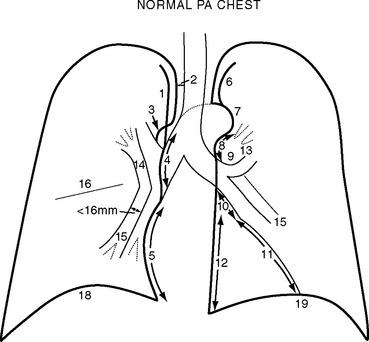
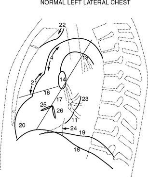
Normal Structures on the Erect Posteroanterior Chest Radiograph
Normal structures identified on the PA and left lateral radiographs are shown in Figs. 6-1 and 6-2.
Systematic Approach to Examining Chest Radiographs
PREOPERATIVE CHEST RADIOGRAPH
Cardiac Chamber Enlargement
The PA and lateral chest radiographs can suggest specific valvular or chamber abnormalities.
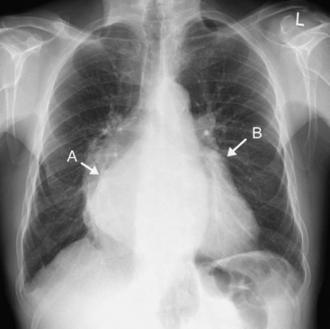
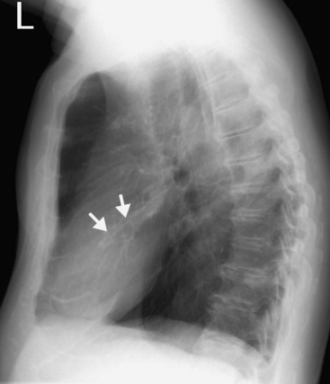
Left Atrial Enlargement
Radiographic signs of left atrial enlargement include (Fig. 6-3):
Right Ventricular Enlargement
Right Atrial Enlargement
Cardiac Calcification
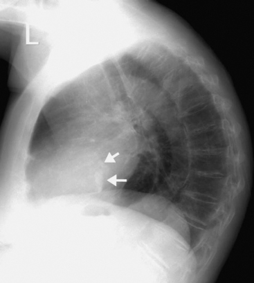
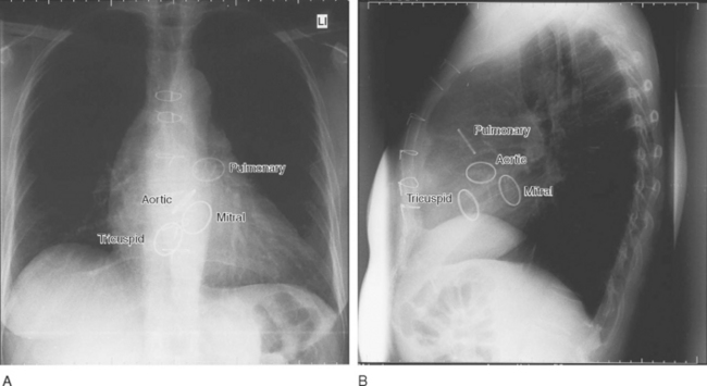
Calcification can be present in many cardiac structures, including the pericardium, the cardiac valves, and the walls of the cardiac chambers, as well as in organized thrombus and in the coronary arteries due to atheroma. Aortic valve calcification can be seen on the lateral radiograph as a ring of calcification projected centrally over the heart (Fig. 6-4). The presence of aortic valve calcification implies stenosis. Mitral annular calcification is common in patients more than 70 years of age; it appears as a C-shaped ring near the posterior and inferior aspects of the heart on the lateral radiograph (Fig. 6-5). Mitral annular calcification does not imply functional impairment of the mitral valve. In contrast, calcification of the mitral leaflets is associated with rheumatic heart disease and usually indicates significant mitral valve dysfunction, usually stenosis. Mitral leaflet calcification is seen in the same region as annular calcification but is punctate and lacks the C-shape of the more benign annular calcification. The positions of each of the four heart valves on frontal and lateral radiographs are shown in Figure 6-6.
Hiatus Hernia
Hiatus hernia results in a retrocardiac mass that is predominantly left-sided but can bulge slightly to the right of the midline on a frontal radiograph. Such hernias are common and are best appreciated on an erect chest radiograph, on which they can usually be seen to contain an air fluid level. On a supine film, a hiatus hernia may be mistaken for a left basal pneumothorax.
Pulmonary Vascularity
Pulmonary Arterial Hypertension
Signs suggestive of pulmonary arterial hypertension include:
On thoracic CT, the signs of pulmonary arterial hypertension include a transverse diameter of the main pulmonary artery greater than that of the adjacent ascending aorta as well as the presence of pericardial fluid and minor pericardial thickening.1
Pulmonary Venous Hypertension and Pulmonary Edema
Three changes in pulmonary vascularity occur in patients with raised left atrial pressure:
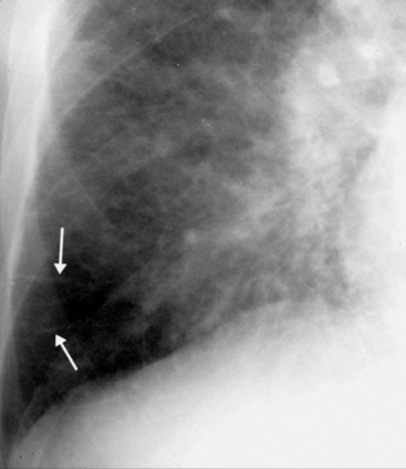
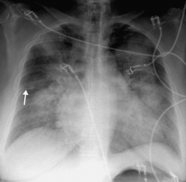
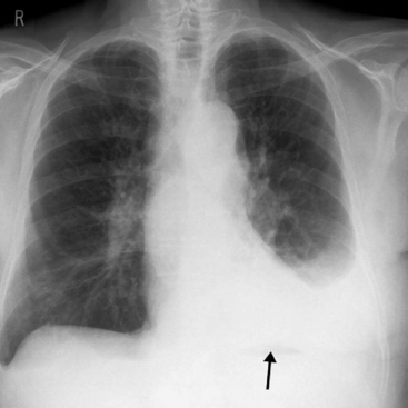
Figure 6.8 AP radiograph, patient erect, showing alveolar pulmonary edema. The perihilar and symmetric nature of the infiltrates favors a diagnosis of alveolar pulmonary edema over ARDS (see Fig. 6-17). Interstitial fluid, as demonstrated by the thickening of the horizontal fissure (arrow), can also be seen.
POSTOPERATIVE AND POSTPROCEDURE CHEST RADIOGRAPHS
Lines and Tubes
The best positions for certain lines and tubes are shown in Figure 6-9.
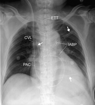
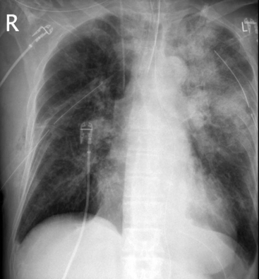
Figure 6.9 Chest radiograph, patient supine, demonstrating multiple lines and tubes. An endotracheal tube (ETT), central venous line (CVL), pulmonary artery catheter (PAC), intraaortic balloon pump (IABP), along with three pleural drains (arrows) can be seen. The outline of the inflated IABP can be seen, which indicates that the radiograph has been taken during diastole. Sternal wires and clips on the internal mammary artery can be seen. In addition, there is left lower lobe collapse (see Fig. 6-16).
Endotracheal Tube
The ideal position for the tip of an endotracheal tube is in the midthoracic trachea, approximately 3 to 4 cm above the carina. Lower positions may result in the migration of the tube into the right main bronchus, and more proximal positions may result in accidental extubation, particularly with neck flexion. The carina lies at the level of the fifth or sixth thoracic vertebral body.2
Pleural and Mediastinal Drains
Malposition of pleural drains is a common cause of patient morbidity. Emergently placed chest tubes are particularly prone to malposition; on CT scan review, as much as 26% of intercostal drains are found to have been misplaced. The most common misplacement is interfissural positioning.3 The interlobar fissures are commonly incomplete, and pulmonary lacerations with pneumothorax, hemothorax, or bronchopleural fistulae can result from such tube positions. A correctly placed pleural drain usually has a curved intrathoracic course, whereas an interfissural tube has a straight intrathoracic course, and the tube tip is directed at the pulmonary hilum.4 If there is doubt about the tube position it may be verified by thoracic CT scan.
Central Venous Catheters
The optimal position for a central venous catheter is for the tip of the catheter to be in the superior vena cava outside the pericardium above the superior vena cava/right atrial junction. A catheter within the right atrium may cause cardiac arrhythmias and, rarely, cardiac perforation. On frontal radiograph, the tip of the catheter should be above the level of the angle between the right main bronchus and the trachea.5 Central venous catheters that are kinked or have curved into the wall of a vein may also cause perforation and should be repositioned.
Nasogastric and Nasojejunal Tubes
A nasojejunal tube should lie with its tip in the proximal jejunum, just beyond the duodenojejunal flexure. Correct placement of a nasojejunal tube is identified by observation that the tube passes across the midline (from the patient’s left to right) and curls in a semicircle to lie with the tip back on the left of the patient’s midline (see Fig. 34-4). Occasionally, in a patient with marked gastric distension, the stomach may extend across the midline, making it difficult to be sure of correct placement. The position can be confirmed by fluoroscopic-contrast examination.
Mediastinum
Mediastinal Widening
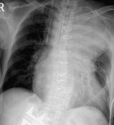
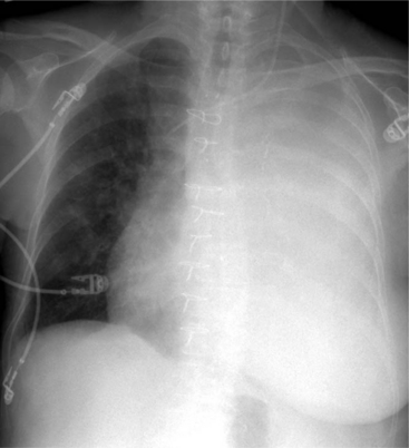
Mediastinal widening is an almost universal finding following cardiac surgery. Widening of up to 50% from the preoperative PA chest film to the postoperative AP supine film is a normal finding. Mediastinal widening of 70% or more (Fig. 6-10) is indicative of mediastinal bleeding and is associated with an increased need for surgical reexploration.6 The differential diagnosis includes upper lobe collapse or consolidation.
Pericardial Effusion
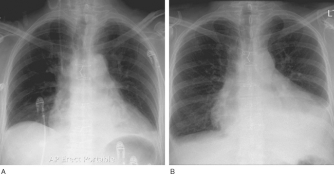
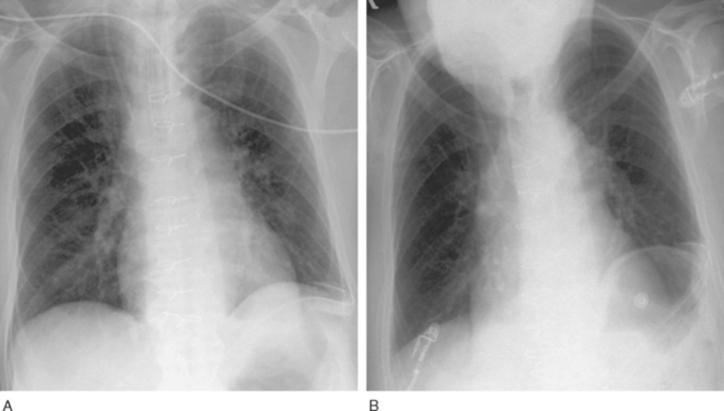
The AP chest radiograph has low sensitivity and specificity for determining the presence of hemodynamically significant pericardial collections in patients after cardiac surgery. Radiographic signs indicating the need for further investigation (usually with echocardiography) include a globular cardiac shadow and a significant increase in apparent cardiac size over a short time interval (Fig. 6-11, A and B).
Lung Collapse
Right Upper Lobe Collapse
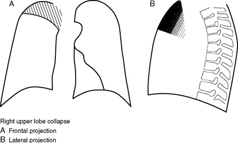
The right upper lobe (Fig. 6-12) collapses medially and the horizontal fissure swings superiorly, creating a well-demarcated density medially in the right upper thorax. The pulmonary hilum on the right is elevated. The trachea is deviated to the right. The right paratracheal stripe and superior vena cava are not visualized. Right upper lobe collapse may be mistaken for mediastinal hematoma, with volume loss tending to support the diagnosis of collapse. Right upper lobe collapse may occur in a ventilated patient due to obstruction by the endotracheal tube of a right upper lobe bronchus that originates in the distal trachea (a variant of normal anatomy).
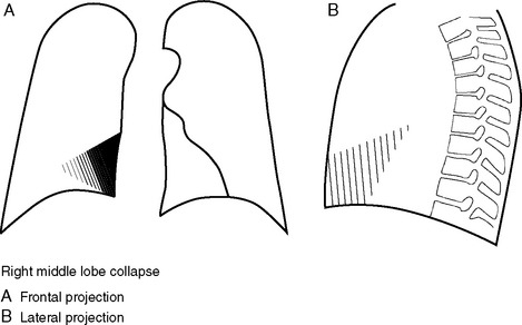
Right Middle Lobe Collapse
Right middle lobe collapse (Fig. 6-13) is more obvious on a lateral projection than a frontal image. The lobe collapses medially to lie adjacent to the right heart border, and this causes loss of definition of a portion of the right heart border. The horizontal fissure will not be visible. On the lateral projection there is a triangular density in the anterior inferior thorax with the apex pointing towards the hilum.
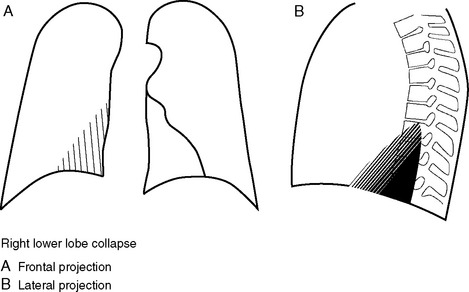
Right Lower Lobe Collapse
The right lower lobe (Fig. 6-14) collapses medially, posteriorly, and inferiorly, creating a wedge of increased density in the right lower thorax. The right lower lobe pulmonary artery is not visualized because of the increased parenchymal density around it. The right hemidiaphragm may be raised, reflecting volume loss. The lateral projection demonstrates increased density overlying the lower vertebrae, and the right hemidiaphragm is obscured.
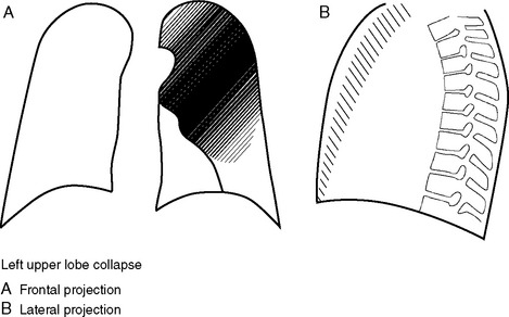
Left Upper Lobe Collapse
The left upper lobe (Fig. 6-15) includes the lingula. This lobe collapses anteriorly and reveals no sharp interface on the frontal film; rather, a veiling density is seen over the left upper thorax because the aerated lower lobe is being seen through the collapsed upper lobe. The upper mediastinum and trachea are displaced to the left, and the left hilum is elevated. The left heart border is indistinct due to loss of air from the lingula. On the lateral radiograph, a dense vertical band of collapsed lung is seen anteriorly.
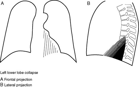
Left Lower Lobe Collapse
The pattern of left lower lobe collapse (Fig. 6-16) mirrors that of the right lower lobe, but the features may be less readily appreciated because the left lower lobe is behind the density of the heart. On the frontal view there is a triangular density behind the heart combined with loss of visualization of the left lower lobe pulmonary artery, inferior displacement of the left hilum, and elevation of the left hemidiaphragm. The descending aorta is indistinct because of the dense lung adjacent to it. On the lateral projection there is increased density overlying the lower vertebrae and loss of the left hemidiaphragm.
Acute Respiratory Distress Syndrome
In the early stages of acute respiratory distress syndrome (ARDS), the chest radiograph may be normal or demonstrate only hazy pulmonary opacities. With time, the presentation progresses to patchy consolidation (Fig. 6-17). In a supine patient, consolidation is typically most extensive in the posterior and inferior aspects of the lower lobes. Pleural effusions and atelectasis are common.
On plain radiography, it can be difficult to make the distinction between cardiogenic pulmonary edema and ARDS. In general, cardiogenic pulmonary edema demonstrates more interstitial thickening, whereas ARDS demonstrates more consolidation on air bronchograms. In cardiogenic pulmonary edema, the development of symptoms tends to mirror radiographic findings, whereas in ARDS, hypoxemia may precede radiographic abnormalities. CT scanning in ARDS demonstrates regions of consolidation, dependant atelectasis, and pleural fluid (see Fig. 27-2) and is useful for the detection of lung abscesses or small pneumothoraces.8
Pleural Effusion
Chest Radiograph, Erect
Small volumes of free fluid result in a slight blunting of the lateral costophrenic angles associated with separation of the inferior and lateral lung from the adjacent costal margin. Fluid accumulates in the posterior costophrenic recess, obscuring vessels below the hemidiaphragm. As the volume of fluid increases, a fluid meniscus develops on the lateral chest wall (Fig. 6-18).
Large quantities of pleural fluid may occasionally collect under the lung and not track up the lateral chest wall. This is termed subpulmonic effusion (Fig. 6-19). The chest radiograph demonstrates apparent elevation and lateral tenting of the hemidiaphragm. On the left, a subpulmonic effusion can be differentiated from elevation of the hemidiaphragm by the separation of the apparent diaphragm from the gastric air bubble.
Chest Radiograph, Supine
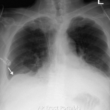
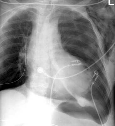
On a chest radiograph taken when the patient is supine, free fluid pools posteriorly in the thorax and creates a veiling density over the hemithorax (Fig. 6-20). The persistent visualization of pulmonary vessels is suggestive of the extrapulmonary nature of the increased density. A pleural cap may be evident at the apex of the lung. The perception of pleural fluid is reduced when the patient is supine, and large effusions may not be recognized.
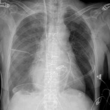
Figure 6.20 Chest radiograph, patient supine, showing a right pleural fluid collection. A veiling density can be seen over the hemithorax. Fluid can also be seen in the horizontal fissure. An aortic prosthetic valve and mitral and tricuspid annuloplasty bands are also seen. Other standard postoperative lines and tubes are also present (see Fig. 6-9).
Ultrasound Imaging
The sonographic estimation of fluid volume is most accurate when the patient is scanned from the back while seated erectly because fluid collects in the posterior costophrenic recess. Alternatively, in the ICU, bedside fluid volume may be estimated with the patient semireclined or in a partial decubitus position, but these positions are less accurate for evaluating small effusions. Draining a collection is facilitated by marking the skin at an appropriate site or by real-time ultrasound-guided placement of a pleural tube. Ultrasound imaging has a tendency to underestimate the volume of fluid. Interfissural collections may not be apparent because ultrasound is unable to image through air to reveal the fluid collection. Ultrasound imaging is highly operator-dependent, and images are prone to being misinterpreted by inexperienced observers.9
Computed Tomography Scanning
CT scanning is the most sensitive and specific means of demonstrating pleural fluid and is the imaging modality of choice for complex pleural fluid collections. The morphology of the fluid collection can provide important clues about whether the fluid is free or loculated. Free fluid tends to layer in a dependent fashion. Pleural thickening suggests a diagnosis of empyema, particularly if there is pleural enhancement with contrast or if there are signs of edema in the chest wall.10 CT scanning may not be able to identify septations within fluid collections that can impede percutaneous drainage; septations are best assessed by ultrasound imaging.
Causes of Pleural Effusions in the Cardiothoracic ICU
Left-sided pleural effusions are common following coronary artery bypass graft surgery. Their occurrence has been attributed to a combination of heart failure and impaired pleural fluid clearance resulting from dissection of the internal mammary artery and pleurotomy.11
Rare causes of pleural effusions include:
Pneumothorax
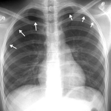
Chest Radiograph, Erect
When a patient is erect, a film shows air rising in the pleural space and separating the lung from the chest wall, particularly at the lung apex (Fig. 6-21). Films taken on expiration do not convincingly increase the pickup rate for pneumothorax.13 False-positives for pneumothorax can occur because of any linear density overlying the apex and lateral aspect of the thorax, particularly overlying skin folds (Fig. 6-22), but also vascular catheters, hair, clothing, and bedding. Skin folds are a common finding in the AP chest radiographs of elderly patients because redundant skin is compressed by the radiographic plate. Skin folds may extend outside of the confines of the thoracic cavity, and lung markings may be visible lateral to the line of the fold. If there is confusion about the presence of a pneumothorax or an artifact, the patient should be repositioned and a repeat radiograph should be performed.
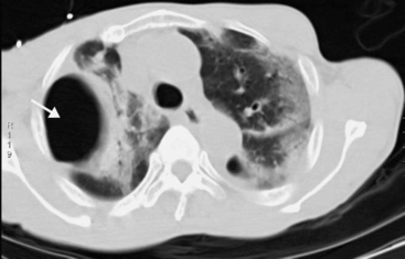
Bullae can be difficult to distinguish from pneumothoraces. Bullae are limited to an anatomic lobe of the lung and do not adopt the shape of the pleural space. Review of old radiographs may be helpful. CT scanning can differentiate a pneumothorax from a bulla by demonstrating the internal structure within the airspace of a bulla and the visceral pleura around a pneumothorax.14 Bullae tend to be oval-shaped (Fig. 6-23), whereas pneumothoraces are typically lens-shaped.
In a tension pneumothorax, the volume of the pneumothorax is usually large and there are signs of mediastinal displacement, diaphragm flattening, and ipsilateral lung collapse. Dynamic hyperinflation following single-lung transplantation can be mistaken for a pneumothorax (see Fig. 13-2). Collapse or fluid on the contralateral side can also give the impression of a pneumothorax.
Chest Radiograph, Supine
Bronchopleural Fistula
A direct communication between an airway and the pleural space is called a bronchopleural fistula. After pneumonectomy, the presence of a bronchopleural fistula is suggested by a decrease in the volume of fluid and an increase in the volume of air in the post-pneumonectomy space (see Fig. 12-6). There may be changes of pneumonia on the contralateral side as a consequence of aspiration. The volume of the affected hemithorax may increase, as demonstrated by a shift of the mediastinum toward the contralateral side, reversing a trend toward reduced volume on the operated side. CT scanning with fine slices and multiplanar reconstructions may identify the site of the fistula.16
Chest Wall and Diaphragm
Sternum
On the chest radiograph, sternal dehiscence is seen as disruption of or alteration in the orientation of the sternal wires and a widening of the junction line between the two sternal halves. Dehiscence is often accompanied by sternal infection. On CT, sternal osteomyelitis results in sternal destruction and fluid collections around the sternum or between the two halves of the sternotomy.17
Diaphragm
Impaired diaphragmatic function due to phrenic nerve injury is common following cardiac surgery. The left hemidiaphragm is the most commonly affected. On a plain radiograph, phrenic nerve paresis is revealed by a raised hemidiaphragm, which commonly becomes apparent after extubation (Fig. 6-25, A and B). Phrenic nerve injury can cause, and also be mistaken for, lower lobe atelectasis. In nonventilated patients, diaphragmatic motion can be assessed at the bedside by ultrasound imaging. Motion is graded as being normal, reduced, absent, or paradoxic. There is strong agreement between absent and paradoxic diaphragmatic motion and impaired phrenic nerve conduction with electrophysiologic testing. Most phrenic nerve injuries that occur as a consequence of cardiac surgery have resolved after 12 months.18
Subdiaphragmatic Air
Subdiaphragmatic air is common following cardiac surgery; it occurs as the result of opening the peritoneal space at the inferior extent of the median sternotomy or during placement of mediastinal and pleural drains. Usually, only small volumes of air are introduced and they escape detection on a chest radiograph taken when a patient is in the supine position, becoming evident only when the first image is obtained in a patient who is erect. Following laparotomy, pneumoperitoneum may persist for more than 2 weeks.19 An increased volume of free air revealed by consecutive radiographs raises the possibility of perforated abdominal viscus and warrants further investigation. If a perforated viscus is suspected and the patient cannot sit up, a plain abdominal radiograph may be obtained when the patient has been placed in a right-sided decubitus position. CT scanning is indicated if further radiologic investigation is required.
SICK PATIENT WITH AN ABNORMAL CHEST RADIOGRAPH
Three important abnormalities viewed on chest radiographs demand immediate attention. The abnormalities and possible diagnoses are outlined in Table 6-1.
Table 6-1 Critical Abnormalities on Chest Radiographs and Possible Causes
| Abnormality | Possible Causes |
|---|---|
| Whiteout hemithorax (Fig. 6-26) | Massive hemothorax or pleural collection |
| There is no volume loss; there may be volume gain. | |
| There may be signs of tension, including flattening and eversion of the hemidiaphragm and displacement of the heart and mediastinum to the contralateral side. | |
| Lung collapse | |
| It is often but not always caused by endobronchial intubation. | |
| The position of the endotracheal tube should be checked. | |
| There may be volume loss, with mediastinal shift toward the affected side. | |
| Lucent hemithorax (Fig. 13-2A) | Large pneumothorax or tension pneumothorax |
| There may be signs of tension, with mediastinal shift away from the affected side. | |
| Unilateral dynamic hyperinflation after single lung transplantation. | |
| Collapse or pleural fluid on the contralateral side. | |
| Very wide mediastinum (Fig. 6-10) | Postoperative hemorrhage, particularly involving the internal mammary artery bed. |
| There may be pericardial effusion. | |
| There may be a central venous catheter accident. |
1 Ng CS, Wells AU, Padley SP. A CT sign of chronic pulmonary arterial hypertension: the ratio of main pulmonary artery to aortic diameter. J Thorac Imaging. 1999;14:270-278.
2 Goodman LR, Conrardy PA, Laing F, et al. Radiographic evaluation of endotracheal tube position. Am J Roentgenol. 1976;127:433-434.
3 Baldt MM, Bankier AA, Germann PS, et al. Complications after emergency tube thoracostomy: assessment with CT. Radiology. 1995;195:539-543.
4 Kurihara Y, Galvin JR, Thompson BH, et al. The utility of the frontal chest radiograph in the evaluation of chest drain placement. Clin Radiol. 1996;51:350.
5 Rutherford JS, Merry AF, Occleshaw CJ. Depth of central venous catheterization: an audit of practice in a cardiac surgical unit. Anaesth Intens Care. 1994;22:267-271.
6 Goodman LR, Kay HR, Teplick SK, et al. Complications of median sternotomy: computed tomographic evaluation. Am J Roentgenol. 1983;141:225-230.
7 Akman C, Kantarci F, Cetinkaya S. Imaging in mediastinitis: a systematic review based on aetiology. Clin Radiol. 2004;59:573-585.
8 Desai SR. Acute respiratory distress syndrome: imaging of the injured lung. Clin Radiol. 2002;57:8-17.
9 Koh DM, Burke S, Davies N, et al. Transthoracic US of the chest: clinical uses and applications. Radiographics. 2002;22:e1.
10 Waite RJ, Carbonneau RJ, Balikian JP, et al. Parietal pleural changes in empyema: appearances at CT. Radiology. 1990;175:145-150.
11 Kollef MH. Chronic pleural effusion following coronary artery revascularization with the internal mammary artery. Chest. 1990;97:750-751.
12 Prince SE, Cunha BA. Postpericardiotomy syndrome. Heart Lung. 1997;26:165-168.
13 Seow A, Kazerooni EA, Pernicano PG, et al. Comparison of upright inspiratory and expiratory chest radiographs for detecting pneumothoraces. Am J Roentgenol. 1996;166:313-316.
14 Phillips GD, Trotman-Dickenson B, Hodson ME, et al. Role of CT in the management of pneumothorax in patients with complex cystic lung disease. Chest. 1997;112:275-278.
15 Kong A. The deep sulcus sign. Radiology. 2003;228:415-416.
16 Kim EA, Lee KS, Shim YM, et al. Radiographic and CT findings in complications following pulmonary resection. Radiographics. 2002;22:67-86.
17 Boiselle PM, Mansilla AV, White CS, et al. Sternal dehiscence in patients with and without mediastinitis. J Thorac Imaging. 2001;16:106-110.
18 DeVita MA, Robinson LR, Rehder J, et al. Incidence and natural history of phrenic neuropathy occurring during open heart surgery. Chest. 1993;103:850-856.
19 Gayer G, Jonas T, Apter S, et al. Postoperative pneumoperitoneum as detected by CT: prevalence, duration, and relevant factors affecting its possible significance. Abdom Imaging. 2000;25:301-305.
[/level-membership-for-cardiothoracic-surgery-category][not-level-membership-for-cardiothoracic-surgery-category]
Chapter 6 Chest Radiography
Skilled interpretation of chest radiographs is central to the diagnosis and treatment of patients in the cardiothoracic intensive care unit (ICU). In this chapter the common abnormalities of chest radiographs that are encountered in cardiac surgery patients are reviewed. Where appropriate, indications for computed tomography (CT) or ultrasound scanning of the chest are discussed. Before attempting to interpret abnormalities, it is essential to appreciate the findings of the normal chest radiograph and to have a systematic approach to reviewing films. These topics are discussed first.
NORMAL CHEST RADIOGRAPH
Types of Chest Radiographs
Two types of frontal chest radiographs may be obtained:
Normal Structures on the Erect Posteroanterior Chest Radiograph
Normal structures identified on the PA and left lateral radiographs are shown in Figs. 6-1 and 6-2.
Systematic Approach to Examining Chest Radiographs
PREOPERATIVE CHEST RADIOGRAPH
Cardiac Chamber Enlargement
The PA and lateral chest radiographs can suggest specific valvular or chamber abnormalities.
Left Atrial Enlargement
Radiographic signs of left atrial enlargement include (Fig. 6-3):
Right Ventricular Enlargement
Right Atrial Enlargement
Cardiac Calcification
Calcification can be present in many cardiac structures, including the pericardium, the cardiac valves, and the walls of the cardiac chambers, as well as in organized thrombus and in the coronary arteries due to atheroma. Aortic valve calcification can be seen on the lateral radiograph as a ring of calcification projected centrally over the heart (Fig. 6-4). The presence of aortic valve calcification implies stenosis. Mitral annular calcification is common in patients more than 70 years of age; it appears as a C-shaped ring near the posterior and inferior aspects of the heart on the lateral radiograph (Fig. 6-5). Mitral annular calcification does not imply functional impairment of the mitral valve. In contrast, calcification of the mitral leaflets is associated with rheumatic heart disease and usually indicates significant mitral valve dysfunction, usually stenosis. Mitral leaflet calcification is seen in the same region as annular calcification but is punctate and lacks the C-shape of the more benign annular calcification. The positions of each of the four heart valves on frontal and lateral radiographs are shown in Figure 6-6.
Hiatus Hernia
Hiatus hernia results in a retrocardiac mass that is predominantly left-sided but can bulge slightly to the right of the midline on a frontal radiograph. Such hernias are common and are best appreciated on an erect chest radiograph, on which they can usually be seen to contain an air fluid level. On a supine film, a hiatus hernia may be mistaken for a left basal pneumothorax.
Pulmonary Vascularity
Pulmonary Arterial Hypertension
Signs suggestive of pulmonary arterial hypertension include:
On thoracic CT, the signs of pulmonary arterial hypertension include a transverse diameter of the main pulmonary artery greater than that of the adjacent ascending aorta as well as the presence of pericardial fluid and minor pericardial thickening.1
Pulmonary Venous Hypertension and Pulmonary Edema
Three changes in pulmonary vascularity occur in patients with raised left atrial pressure:
Figure 6.8 AP radiograph, patient erect, showing alveolar pulmonary edema. The perihilar and symmetric nature of the infiltrates favors a diagnosis of alveolar pulmonary edema over ARDS (see Fig. 6-17). Interstitial fluid, as demonstrated by the thickening of the horizontal fissure (arrow), can also be seen.
[/not-level-membership-for-cardiothoracic-surgery-category]
