[level-membership-for-critical-care-medicine-category]
Cardiovascular Therapeutic Management
Pacemakers
Pacemakers are electronic devices that can be used to initiate the heartbeat when the heart’s intrinsic electrical system cannot effectively generate a rate adequate to support cardiac output. Pacemakers may be used temporarily, either supportively or prophylactically, until the condition responsible for the rate or conduction disturbance resolves. They also may be used on a permanent basis if the patient’s condition persists despite adequate therapy. The use of permanent pacemakers as a form of device-based therapy has expanded significantly in the last decade.1
Indications for Temporary Pacing
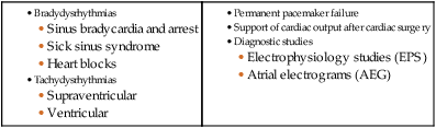
The clinical indications for instituting temporary pacemaker therapy are similar regardless of the cause of the rhythm disturbance that necessitates the placement of a pacemaker (Box 16-1). The causes range from ischemia and electrolyte imbalances to sequelae related to acute myocardial infarction (MI) or cardiac surgery.
Diagnostic Indications
Several diagnostic uses for temporary pacing have evolved. Electrophysiology studies (EPS) are performed in cardiac catheterization laboratories equipped with specialized pacing equipment. During an EPS, catheters with pacing electrodes are used to diagnose the patient’s potential for dysrhythmias.2 These electrodes are used to induce dysrhythmias in patients with recurrent symptomatic tachydysrhythmias. This allows the physician to closely evaluate the particular dysrhythmia and determine appropriate therapy. For those patients whose tachydysrhythmia is found to be refractory to conventional antidysrhythmic therapy, radiofrequency (RF) current catheter ablation of the responsible tissue can be done safely and effectively in the electrophysiology laboratory. After a mapping procedure has localized the site of dysrhythmia formation, short bursts of RF current are delivered through the catheter, destroying the offending tissue with heat. Ablation has been shown to be an effective treatment for patients with symptomatic supraventricular tachycardias that result from atrioventricular (AV) node re-entry or accessory pathways, such as Wolff-Parkinson-White syndrome.3,4 Catheter ablation may also be used as a therapeutic strategy for selected patients with atrial fibrillation.5
Intracardiac electrograms—recordings of cardiac electrical activity obtained from pacing electrodes—may provide useful diagnostic information. The atrial electrogram (AEG) is an amplified recording of atrial activity that can be obtained through the use of an atrial pacing electrode or an esophageal pill electrode and a standard electrocardiogram (ECG) machine. It may be used after cardiac surgery to facilitate the diagnosis of supraventricular dysrhythmias in patients with temporary atrial epicardial wires already in place.6
The Pacemaker System
Pacing Lead Systems
The bipolar lead used in transvenous pacing has two electrodes on one catheter (Fig. 16-1). The distal, or negative, electrode is at the tip of the pacing lead and is in direct contact with the heart, usually inside the right atrium or ventricle. Approximately 1 cm from the negative electrode is a positive electrode. The negative electrode is attached to the negative terminal, and the positive electrode is attached to the positive terminal of the pulse generator, either directly or by means of a bridging cable (see Fig. 16-1B).
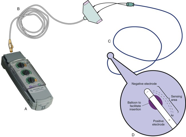
A unipolar pacing system (epicardial or transvenous) has only one electrode (the negative electrode) making contact with the heart. For a permanent pacemaker, the positive electrode can be created by the metallic casing of the subcutaneously implanted pulse generator (Fig. 16-2), or as is the case with a unipolar epicardial lead system, the positive electrode can be formed by a piece of surgical steel wire sewn into the subcutaneous tissue of the chest or the metal portion of a surface ECG electrode.
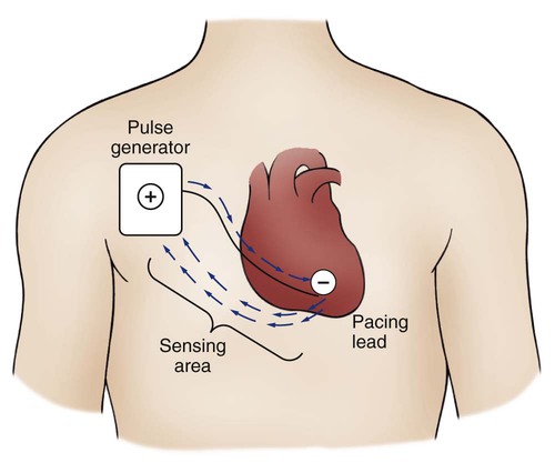
Because the unipolar pacing system has a wide sensing area as a result of the relatively long distance between the negative and positive electrodes, it has better sensing capabilities than does a bipolar system. However, this feature makes the unipolar system more susceptible to sensing extraneous signals, such as the electrical artifacts created by normal muscle movements (i.e., myopotentials) or by external electromagnetic interference (EMI), which may result in inappropriate inhibition of the pacing stimulus. This problem is of more concern in permanent pacing systems, in which the “can” of the pacemaker generator may be used as a part of the pacing circuit. Because the can is located near a large muscle mass, upper body movement can result in the inappropriate sensing of myopotentials.7
Pacing Routes
Several routes are available for temporary cardiac pacing (Box 16-2). Permanent pacing usually is accomplished transvenously, although when a thoracotomy is otherwise indicated, as in cardiac surgery, the physician may elect to insert permanent epicardial pacing wires.
Transcutaneous cardiac pacing involves the use of two large skin electrodes, one placed anteriorly and the other posteriorly on the chest, connected to an external pulse generator. It is a rapid, noninvasive procedure that nurses can perform in the emergency setting and is recommended in the advanced cardiac life support (ACLS) algorithm for the treatment of symptomatic bradycardia that does not respond to atropine.8 Improved technology related to stimulus delivery and the development of large electrode pads that help disperse the energy have helped reduce the pain associated with cutaneous nerve and muscle stimulation. Discomfort may still be an issue for some patients, particularly when higher energy levels are required to achieve capture. This route is typically used as a short-term therapy until the situation resolves or another route of pacing can be established.
The insertion of temporary epicardial pacing wires has become a routine procedure during most cardiac surgical cases. Ventricular and, in many cases, atrial pacing wires are loosely sewn to the epicardium. The terminal pins of these wires are pulled through the skin before the chest is closed. If both chambers have pacing wires attached, the atrial wires exit subcostally to the right of the sternum and the ventricular wires exit in the same region but to the left of the sternum. These wires can be removed several days after surgery by gentle traction at the skin surface with minimal risk of bleeding.9
Five-Letter Pacemaker Codes
In the 1960s, pacemaker terminology was limited to fixed-rate and demand pacing; AV sequential pacing was introduced in the early 1970s. Although these terms are still useful for understanding pacemaker function (Box 16-3), the continued expansion of functional capabilities of pulse generators has made it necessary to develop a more precise classification system. In 1974, the Inter-Society Commission for Heart Disease (ICHD) adopted a three-letter code for describing the various pacing modalities available. The code has since undergone several revisions, including the addition of two more letters representing programming characteristics and multisite pacing functions, to accommodate the development of newer devices that are rate responsive or that pace from more than one site within the atria and the ventricles. Table 16-1 describes the current five-letter code.10 The original three-letter code remains adequate to describe temporary pacemaker function.
TABLE 16-1
| POSITION I: CHAMBERS PACED | POSITION II: CHAMBERS SENSED | POSITION III: RESPONSE TO SENSING | POSITION IV: RATE MODULATION | POSITION V: MULTISITE PACING |
| 0 = None | 0 = None | 0 = None | 0 = None | 0 = None |
| A = Atrium | A = Atrium | T = Triggered | R = Rate Modulation | A = Atrium |
| V = Ventricle | V = Ventricle | I = Inhibited | V = Ventricle | |
| D = Dual (A + V) | D = Dual (A + V) | D = Dual (T + I) | D = Dual (A + V) |
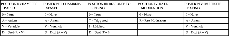
Modified from Bernstein AD, et al. The Revised NASPE/BPEG generic pacemaker code for antibradycardia, adaptive-rate and multisite pacing. PACE. 2002;25:260.
The original code is based on three categories, each represented by a letter. The first letter refers to the cardiac chamber that is paced. The second letter designates which chamber is sensed, and the third letter indicates the pacemaker’s response to the sensed event. These three letters are used to describe the mode of pacing. For example, a VVI pacemaker paces the ventricle when the pacemaker fails to sense an intrinsic ventricular depolarization, but sensing of a spontaneous ventricular depolarization inhibits ventricular pacing. A VOO pacemaker paces the ventricle at a fixed rate and has no sensing capabilities. In DDD pacing, atrial and ventricular leads are used for pacing and sensing. In response to sensed activity, the pacemaker inhibits the pacing stimulus; a sensed P wave in the atrium inhibits the atrial spike, and a sensed R wave in the ventricle inhibits the ventricular pacing spike. A sensed P wave may also be used to trigger a ventricular pacing stimulus if normal conduction through the AV node is impaired. Table 16-2 provides a description of temporary pacing modes.
TABLE 16-2
EXAMPLES OF TEMPORARY PACING MODES
| PACING MODE | DESCRIPTION |
| Asynchronous | |
| AOO | Atrial pacing, no sensing |
| VOO | Ventricular pacing, no sensing |
| DOO | Atrial and ventricular pacing, no sensing |
| Synchronous | |
| AAI | Atrial pacing, atrial sensing, inhibited response to sensed P waves |
| VVI | Ventricular pacing, ventricular sensing, inhibited response to sensed QRS complexes |
| DVI | Atrial and ventricular pacing, ventricular sensing; both atrial and ventricular pacing are inhibited if a spontaneous ventricular depolarization is sensed |
| DDD | Both chambers are paced and sensed; inhibited response of the pacing stimuli to sensed events in their respective chambers; triggered response to sensed atrial activity to allow for rate-responsive ventricular pacing |
Physiologic pacing has traditionally been used to describe modes in which the normal physiologic, or sequential, relationship between atrial and ventricular stimulation and contraction is maintained. AV synchrony increases the volume in the ventricle before contraction and helps to improve cardiac output. This may be achieved with atrial pacing in patients who have an intact conduction system or by dual chamber pacing when atrial-to-ventricular conduction is impaired (i.e., during heart block). More recently, physiologic pacing has evolved to include the maintenance of ventricular synchrony as well. Strategies to achieve this include minimizing the use of ventricular pacing and simultaneous pacing of both right and left ventricles.1
Pacemaker Settings
The rate control (Fig. 16-3) regulates the number of impulses that can be delivered to the heart per minute. The rate setting depends on the physiologic needs of the patient, but it usually is maintained between 60 and 80 beats/min. Pacing rates for overdrive suppression of tachydysrhythmias may greatly exceed these values. Some generators have special controls for overdrive pacing that allow for rates of up to 800 stimuli per minute. If the pacemaker is operating in a dual-chamber mode, the ventricular rate control also regulates the atrial rate.
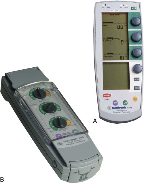
The output dial regulates the amount of electrical current, measured in milliamperes (mA), that is delivered to the heart to initiate depolarization. The point at which depolarization occurs, called threshold, is indicated by a myocardial response to the pacing stimulus (i.e., capture). Threshold can be determined by gradually decreasing the output setting until 1 : 1 capture is lost. The output setting is then slowly increased until 1 : 1 capture is re-established; this threshold to pace is less than 1 mA with a properly positioned pacing electrode. The output is set two to three times higher than threshold, because thresholds tend to fluctuate over time. Box 16-4 details the procedure for measuring pacing thresholds. Separate output controls for atrium and ventricle are used with a dual-chamber pulse generator.
The sensitivity control regulates the ability of the pacemaker to detect the heart’s intrinsic electrical activity. Sensitivity is measured in millivolts (mV) and determines the size of the intracardiac signal that the generator will recognize. If the sensitivity is adjusted to its most sensitive setting—a setting of 0.5 to 1 mV—the pacemaker can respond even to low-amplitude electrical signals coming from the heart. Turning the sensitivity to its least sensitive setting (i.e., adjusting the dial to a setting of 20 mV or to the area labeled async) results in inability of the pacemaker to sense any intrinsic electrical activity and causes the pacemaker to function at a fixed rate. A sense indicator (often a light) on the pulse generator signals each time intrinsic cardiac electrical activity is sensed. A pulse generator may be designed to sense atrial activity or ventricular activity, or both. Box 16-5 describes the procedure for measuring sensitivity. The sensitivity is set at half of the value of the sensitivity threshold to ensure that all appropriate intrinsic cardiac signals are sensed. For example, if the measured sensitivity threshold is 3.0 mV, the generator is set at 1.5 mV. The pacemaker’s sensing ability can be quickly evaluated by observing for a change in pacing rhythm in response to spontaneous depolarizations.
Temporary dual chamber pacemakers have other settings that are required in the DDD mode (see Fig. 16-3B). The lower rate, or base rate, determines the rate at which the generator will pace when intrinsic activity falls below the set rate of the pacemaker. The upper rate determines the fastest ventricular rate the pacemaker will deliver in response to sensed atrial activity. This setting is needed to protect the patient’s heart from being paced in response to rapid atrial dysrhythmias. The pulse width, which can be adjusted from 0.05 to 2 msec, controls the length of time that the pacing stimulus is delivered to the heart. There also is an atrial refractory period, programmable from 150 to 500 msec, which regulates the length of time, after a sensed or paced ventricular event, during which the pacemaker cannot respond to another atrial stimulus. An emergency button is also available on most models to allow for rapid initiation of asynchronous (DOO) pacing during an emergency.
Pacing Artifacts
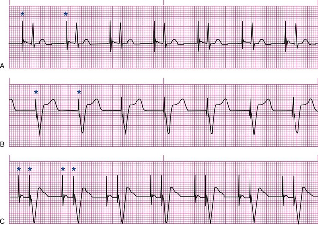
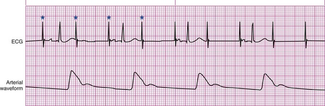
All patients with temporary pacemakers require continuous ECG monitoring. The pacing artifact is the spike that is seen on the ECG tracing as the pacing stimulus is delivered to the heart. A P wave is visible after the pacing artifact if the atrium is being paced (Fig. 16-4A). Similarly, a QRS complex follows a ventricular pacing artifact (see Fig. 16-4B). With dual-chamber pacing, a pacing artifact precedes both the P wave and the QRS complex (see Fig. 16-4C).
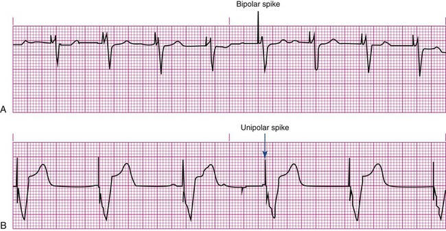
Not all paced beats look alike. For example, the artifact (spike) produced by a unipolar pacing electrode is larger than that produced by a bipolar lead (Fig. 16-5). The QRS complex of paced beats appears different, depending on the location of the pacing electrode. If the pacing electrode is positioned in the RV, a left bundle branch block (LBBB) pattern is displayed on the ECG. A right bundle branch block (RBBB) pattern is visible if the pacing stimulus originates from the left ventricle (LV).
Pacemaker Malfunctions
Pacing Abnormalities
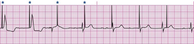
Failure of the pacemaker to deliver the pacing stimulus results in disappearance of the pacing artifact, even if the patient’s intrinsic rate is less than the set rate on the pacer (Fig. 16-6). This can occur intermittently or continuously and can be attributed to failure of the pulse generator or its battery, a loose connection between the various components of the pacemaker system, broken lead wires, or stimulus inhibition as a result of EMI. Tightening connections, replacing the batteries or the pulse generator itself, or removing the source of EMI may restore pacemaker function.
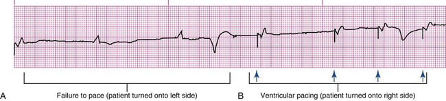
If the pacing stimulus fires but fails to initiate a myocardial depolarization, a pacing artifact will be present but will not be followed by the expected P wave or QRS complex, depending on the chamber being paced (Fig. 16-7). This loss of capture most often can be attributed to displacement of the pacing electrode or to an increase in threshold (electrical stimulus necessary to elicit a myocardial depolarization) as a result of medications, metabolic disorders, electrolyte imbalances, or fibrosis or myocardial ischemia at the site of electrode placement. In many cases, increasing the output (mA) elicits capture. For transvenous leads, repositioning the patient onto the left side may improve lead contact and restore capture.
Pacing can occur at inappropriate rates. For example, impending battery failure in a permanent pacemaker can result in a gradual decrease in the paced rate, also referred to as rate drift. Inappropriate stimuli from a pacemaker may result in a pacemaker-mediated tachycardia. This usually is caused by sensing of inappropriate signals in a dual-chamber pacemaker that is in a trigger mode, such as DDD. The tachycardia can be terminated by placing a magnet over the generator to transiently suspend sensing.11
Sensing Abnormalities
Sensing abnormalities include both undersensing and oversensing.
Undersensing.
Undersensing is the inability of the pacemaker to sense spontaneous myocardial depolarizations. Undersensing results in competition between paced complexes and the heart’s intrinsic rhythm. This malfunction is manifested on the ECG by pacing artifacts that occur after or are unrelated to spontaneous complexes (Fig. 16-8). Undersensing can result in the delivery of pacing stimuli into a relative refractory period of the cardiac depolarization cycle (see Fig. 12-25 in Chapter 12). A ventricular pacing stimulus delivered into the downslope of the T wave (R-on-T phenomenon) is a real danger with this type of pacer aberration, because it may precipitate a lethal dysrhythmia. The nurse must act quickly to determine the cause and initiate appropriate interventions. Often, the cause can be attributed to inadequate wave amplitude (height of the P or R wave). If this is the case, the situation can be promptly remedied by increasing the sensitivity by moving the sensitivity dial toward its lowest setting. Other possible causes include inappropriate (asynchronous) mode selection, lead displacement or fracture, loose cable connections, and pulse generator failure.
Nursing Management
Prevention of Pacemaker Malfunction
It is important to be aware of all sources of EMI within the critical care environment that may interfere with the pacemaker’s function. Sources of EMI in the clinical area include electrocautery, defibrillation current, radiation therapy, magnetic resonance imaging devices, and transcutaneous electrical nerve stimulation (TENS) units.12 In most cases, if EMI is suspected of precipitating pacemaker malfunction, conversion to the asynchronous mode (fixed rate) can maintain pacing until the cause of the EMI is removed.
Microshock Protection
Because the pacing electrode provides a direct, low-resistance path to the heart, the nurse takes special care while handling the external components of the pacing system to avoid conducting stray electrical current from other equipment. Even a small amount of stray current transmitted through the pacing lead could precipitate a lethal dysrhythmia. The possibility of microshock can be minimized by wearing gloves when handling the pacing wires and by proper insulation of terminal pins of pacing wires when they are not in use (Box 16-6). The latter precaution can be accomplished by the use of caps provided by the manufacturer or by improvising with a plastic syringe or section of disposable rubber glove. The wires are taped securely to the patient’s chest to prevent accidental electrode displacement.
 Box 16-6 Patient Safety Alert
Prevention of Microshock

• Wear gloves when handling pacing wires
• Secure all connections between pulse generator, pacing cable, and leads
• Insulate lead tips with nonconducting materials when not attached to generator (manufacturer’s cap, finger cot, plastic syringe)
• Keep dressings and pacing equipment dry
Patient Education
Patient teaching for the person with a temporary pacemaker emphasizes the prevention of complications (Box 16-7). The patient is instructed not to handle any exposed portion of the lead wire and to notify the nurse if the dressing over the insertion site becomes soiled, wet, or dislodged. The patient also is advised not to use any electrical devices brought in from home that could interfere with pacemaker functioning. Patients with temporary transvenous pacemakers need to be taught to restrict movement of the affected extremity to prevent lead displacement.
Permanent Pacemakers
Almost 400,000 permanent pacemakers are implanted annually in the United States, and critical care nurses are likely to encounter these devices in their clinical practice.13 These pacemakers were originally designed to provide an adequate ventricular rate in patients with symptomatic bradycardia. Today, the goal of pacemaker therapy is to simulate, as much as possible, normal physiologic cardiac depolarization and conduction. Sophisticated generators permit rate-responsive pacing, effecting responses to sensed atrial activity (DDD) or to a variety of physiologic sensors (body motion or minute ventilation). For patients who do not have a functional sinus node that can increase their heart rate, rate-responsive pacemakers may improve exercise capacity and quality of life.14 Table 16-3 describes the types of rate-responsive pacing generators in clinical use. The concept of physiologic pacing continues to evolve, because studies have indicated that pacing initiated from the RV apex—even in a dual-chamber mode—may promote heart failure in patients with permanent pacemakers.1 This has prompted further research to identify alternative sites for pacing and modes that can maximize intrinsic AV conduction and minimize ventricular pacing.15
TABLE 16-3
PERMANENT PACEMAKER RATE-RESPONSE PACING MODES
| PULSE GENERATOR | DESCRIPTION |
| AAIR | AAI features plus rate-responsive pacing; used for patients with a symptomatic bradycardia who have a paceable atrium and intact atrioventricular conduction |
| VVIR | VVI features plus rate-responsive pacing; used for patients with an atrium that is unpaceable as a result of chronic atrial fibrillation or other atrial dysrhythmia |
| DDDR | DDD features plus rate-responsive pacing; used for patients with a symptomatic bradycardia in which the atrium is paceable but atrioventricular conduction is, or may become, unreliable |
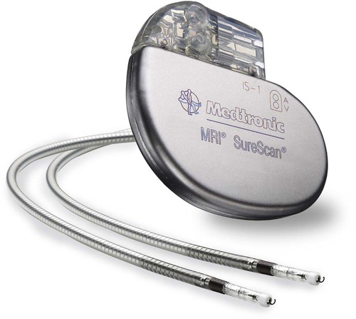
The patient who undergoes implantation of a permanent pacemaker is usually in the hospital for less than 24 hours. Longer lengths of stay are expected for patients with serious complications such as MI or cardiogenic shock. Technologic advances in the computer industry have had a major impact on permanent pacemakers. Microprocessors have allowed for the development of increasingly smaller generators despite the incorporation of more complex features. Today’s generators are smaller, more energy-efficient, and more reliable than previous models. The most recent enhancement has been the release of a pacemaker that is compatible with magnetic resonance imaging (MRI).16 An example of a modern pacemaker is shown in Figure 16-9. A rapidly expanding role for permanent pacemakers has been the use of these devices as a type of nonpharmacologic therapy for treatment of conditions such as heart failure and atrial fibrillation.
Cardiac Resynchronization Therapy
About one third of patients with severe heart failure have ventricular conduction delays (prolonged QRS duration or bundle branch block). These conduction delays have been shown to create a lack of synchrony between the contractions of the LV and RV. The hemodynamic consequences of this dyssynchrony include impaired ventricular filling with decreased ejection fraction, cardiac output, and mean arterial pressure.17 Cardiac resynchronization therapy (CRT) uses atrial pacing plus stimulation of both the LV and RV (biventricular pacing), in an attempt to optimize atrial and ventricular mechanical activity. The CRT device uses three pacing leads, one each in the right atrium and the RV and a specially designed transvenous lead that is inserted through the coronary sinus to pace the LV.18 Because many patients with heart failure are also at risk for sudden cardiac death, biventricular pacing is available on some implantable cardioverter defibrillators (ICDs). A number of clinical trials have shown that CRT improves symptoms, functional status, and mortality in patients with moderate to advanced heart failure.18 New research indicates that CRT may also be beneficial in preventing the progression of heart failure in less symptomatic patients.19
Atrial Fibrillation Suppression
There is a growing incidence of atrial fibrillation, and atrial pacing has been proposed as a possible preventive therapy for this dysrhythmia in selected patients. Atrial pacing in patients with bradycardia has been shown to lower the recurrence of atrial fibrillation, especially compared with ventricular pacing. Atrial-based modes that promote intrinsic conduction and minimize episodes of ventricular pacing are most effective.1 Most pacemakers can be programmed to mode switch to a non–P-wave tracking mode if rapid atrial rates are sensed.20 Strategies for patients with paroxysmal atrial fibrillation, which include pacing both atriums (bi-atrial pacing) and transiently pacing the atrium at a rate higher than the patient’s intrinsic sinus rate, require further study.1
Nursing Management
Nursing management for patients after permanent pacemaker implantation includes monitoring for complications related to insertion and for pacemaker malfunction. Postoperative complications are rare but include cardiac perforation and tamponade, pneumothorax, hematoma, lead displacement, and infection.20,21
Critical care nurses also may be involved in monitoring patients with permanent pacemakers after discharge. Some units are equipped with transtelephonic monitoring equipment that allows patients to transmit information over the telephone from a monitoring device in their home. Transmission of the patient’s ECG can provide information to confirm proper pacemaker function (capture and sensing) and to determine battery status (rate). Newer technology that uses an Internet-based remote monitoring system for pacemaker follow-up offers significant advantages and may soon replace standard transtelephonic ECG evaluation.22
Implantable Cardioverter Defibrillators
An implantable cardioverter defibrillator (ICD) is an electronic device that is used in the treatment of tachydysrhythmias. The ICD is capable of identifying and terminating life-threatening ventricular dysrhythmias. Initially, an ICD was recommended only for patients who had survived an episode of cardiac arrest caused by ventricular fibrillation (VF) or ventricular tachycardia (VT). As clinical trials found improved survival with ICD therapy when compared to treatment with antidysrhythmic medications, ICD use was expanded to include primary prevention of sudden cardiac death.23 Current heart failure guidelines recommend ICD implantation in high-risk patients (i.e., those with a left ventricular ejection fraction less than 35%) even without evidence of VT or VF on an EPS.24 This expanded use of ICDs has resulted in over 100,000 implants per year in the United States.13
The ICD System
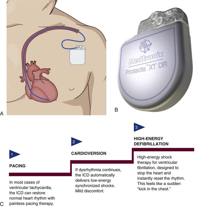
The ICD system consists of leads and a generator and is similar to a pacemaker but with some key differences. The leads contain not only electrodes for sensing and pacing, but also integrated defibrillator coils capable of delivering a shock. The generator is larger, to accommodate a more powerful battery and a high-voltage capacitor, along with the microprocessor.25 It is surgically placed in the subcutaneous tissue of the pectoral region in the upper chest (Fig. 16-10). The early model generators could defibrillate or cardiovert only lethal dysrhythmias. The current generation of devices delivers a tiered therapy, with options for programmable antitachycardia pacing, bradycardia backup pacing, low-energy cardioversion, and high-energy defibrillation. With tiered therapy, antitachycardia pacing is used as the first line of treatment in some cases of VT. If the VT can be pace-terminated successfully, the patient will not receive a shock from the generator and may not even realize that the ICD terminated the dysrhythmia. If programmed bursts of pacing do not terminate the VT, the ICD will cardiovert the rhythm. If the dysrhythmia deteriorates into VF, the ICD is programmed to defibrillate at a higher energy. If the dysrhythmia terminates spontaneously, the device will not discharge. Occasionally, the electrical rhythm may deteriorate to asystole or a slow idioventricular rhythm; in such cases, the bradycardia backup pacing function is activated.
Product development for ICDs has resulted in dual-chamber devices with leads in both atria and ventricles. The introduction of atrial leads allows for dual-chamber pacing to optimize hemodynamic performance and atrial sensing to more accurately discriminate between atrial and ventricular tachycardias and to decrease the incidence of inappropriate shocks. ICDs may also incorporate triple-lead systems (leads in one atrium and both ventricles) to allow for CRT and defibrillation in one device. Other developments in ICD technology include improved diagnostic and telemetry functions, such as the ability to provide real-time electrograms obtained from the ICD electrodes or the ability to perform remote device interrogation by telephone or Internet.25
Insertion of ICD
The ICD has progressed in both programmable functions and insertion technique. Initially, all ICDs were implanted surgically during open heart surgery or via thoracotomy, with electrode patches attached directly to the heart. Today’s smaller generators, combined with the use of transvenous leads, obviate the need for major surgery. Transvenous electrode leads are inserted into the subclavian vein and advanced into the right side of the heart, where contact with the endocardium is achieved. To improve defibrillation efficacy, an additional subcutaneous patch may be placed with some models. The endocardial leads are connected to the generator by tunneling through the subcutaneous tissue, and thoracotomy is avoided. Procedural complications are infrequent but may include hematoma, pneumothorax, or lead dislodgement.26
Nursing Management
If the ICD system was implanted during open heart surgery, the postoperative nursing management is similar to that for any patient undergoing cardiac surgery. If an endocardial lead system is implanted, the nursing management is less intense and the hospital stay is shorter. The nursing management of the patient with an ICD includes assessing for dysrhythmias and monitoring for complications related to insertion. In the case of a ventricular dysrhythmia, it is important to know the type of ICD implanted, how the device functions, and whether it is activated (i.e., on). If the patient experiences a shockable rhythm, the nurse should be prepared to defibrillate in the event that the device fails. During external defibrillation, the paddles or patches should not be placed directly over the ICD generator, as long as this can be accomplished without delay of defibrillation.27 For recurring shocks, patients should be assessed for underlying causes, such as electrolyte imbalance, ischemia, or worsening heart failure.25 Most patients continue to take some antidysrhythmic medications to decrease the number of shocks required and to slow the rate of the tachycardia. Complications associated with the permanent ICD include infection from the implanted system, broken leads, and sensing of supraventricular tachydysrhythmias resulting in unneeded discharges.
Patient Education
To facilitate a positive psychologic adjustment to the ICD, education of the patient and family about the device is vital (Box 16-8). Preoperative teaching for the ICD patient includes information about how the device works and what to expect during the implantation procedure. After implantation, education is focused on aspects of living with an ICD. Patients need information pertaining to scheduled device follow-up and instructions about what to do if they experience a shock. Many institutions have successfully used family support groups for this patient population. Finally, since the ICD is an adjunctive treatment rather than a for cure heart failure, patients need to understand the importance of continued risk-factor modification and prescribed medications.
Fibrinolytic Therapy
Fibrinolytic therapy is an important clinical intervention for the patient experiencing acute ST-elevation myocardial infarction (STEMI). Before the introduction of fibrinolytic agents, medical management of acute MI was focused on decreasing myocardial oxygen demands to minimize myocardial necrosis and preserve ventricular function. Today, efforts to limit the size of the infarction are directed toward timely reperfusion of the jeopardized myocardium through restoration of blood flow in the culprit vessel (the open artery theory). Two options are available for opening the artery—fibrinolytics and mechanical intervention. Although mechanical catheter-based intervention has been proven to yield better outcomes when performed in a timely fashion, only one-third of U.S. hospitals are estimated to have this capability.28 For this reason, fibrinolytic therapy continues to play a major role in the treatment of acute MI.
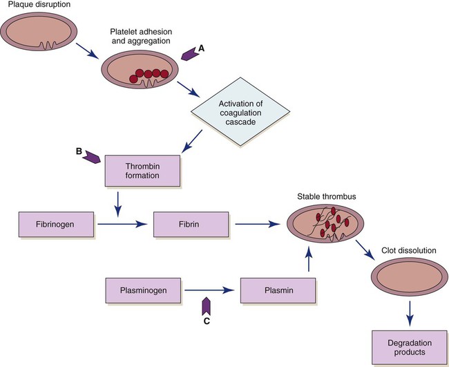
The use of fibrinolytic therapy is predicated on the theory that the significant event in acute coronary syndromes (e.g., unstable angina, acute MI) is the rupture of an atherosclerotic plaque with thrombus formation (Fig. 16-11). The thrombus, which is composed of aggregated platelets bound together with fibrin strands, occludes the coronary artery, depriving the myocardium of oxygen previously supplied by that artery. The administration of a fibrinolytic agent results in lysis of the acute thrombus, resulting in recanalization, or opening, of the obstructed coronary artery and restoration of blood flow to the affected tissue. In addition to restoring perfusion, adjunctive measures (anticoagulants and antiplatelet therapy) are taken to prevent further clot formation and repeat occlusion.
Eligibility Criteria
Certain criteria have been developed, based on research findings, to determine the patient population that would most likely benefit from the administration of fibrinolytic therapy. Patients with recent onset of chest pain (less than 12 hours’ duration) and persistent ST elevation (greater than 0.1 mV in two or more contiguous leads) are considered candidates for fibrinolytic therapy.29 Patients who present with bundle branch blocks that may obscure ST-segment analysis and a history suggesting an acute MI are also considered candidates for therapy (see “Myocardial Infarction” in Chapter 15). The goal of therapy is to administer fibrinolytic therapy within 30 minutes after presentation (“door to needle”), because early reperfusion yields the greatest benefit.30
Exclusion criteria are usually based on the increased risk of bleeding incurred from the use of fibrinolytics. Patients who have stable clots that might be disrupted by fibrinolytic therapy (recent surgery, facial or head trauma,) usually are not considered candidates for fibrinolytic therapy. Other common criteria for the use of fibrinolytic therapy are presented in Box 16-9.
Currently, fibrinolytic therapy is not indicated for patients with unstable angina or non–ST-elevation myocardial infarction (NSTEMIs).31 It is believed that these conditions result from plaque rupture with the formation of an only partially occlusive thrombus. Fibrinolysis breaks up the clot and releases thrombin, and this can paradoxically increase the material necessary for further thrombosis.32 Instead, these patients are treated with antiplatelet agents (e.g., aspirin, clopidogrel, glycoprotein IIb/IIIa inhibitors) and antithrombin medications (e.g., heparin).
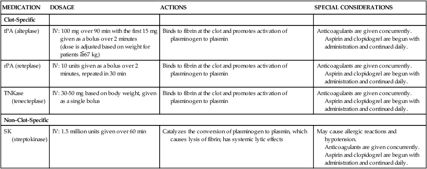
Fibrinolytic Agents
Four fibrinolytic agents are currently available for intravenous treatment of acute STEMI. All of these agents stimulate lysis of the clot by converting inactive plasminogen to plasmin, an enzyme responsible for degradation of fibrin (see Fig. 16-11). The first generation fibrinolytic agents (e.g., streptokinase, urokinase) had their primary effect on circulating plasminogen. Newer fibrinolytic agents (e.g., alteplase, reteplase, tenecteplase) have a greater effect on clot plasminogen than on circulating plasminogen and are therefore considered clot selective. A comparison of currently approved fibrinolytic agents is provided in Table 16-4. Because patients with an area of plaque disruption are still at risk for clot formation and reocclusion, fibrinolytic therapy is used in conjunction with anticoagulants and antiplatelet agents. Current guidelines recommend that anticoagulant therapy be administered for a minimum of 48 hours after reperfusion. Unfractionated heparin (UFH) has been used traditionally, but low–molecular-weight heparin (LMWH) and fondaparinux are also acceptable options.33 Antiplatelet therapy with clopidogrel is recommended for 14 days, and aspirin should be continued indefinitely.30
TABLE 16-4
PHARMACOLOGIC MANAGEMENT
Fibrinolytic Agents for Use in Acute Myocardial Infarction
| MEDICATION | DOSAGE | ACTIONS | SPECIAL CONSIDERATIONS |
| Clot-Specific | |||
| tPA (alteplase) | IV: 100 mg over 90 min with the first 15 mg given as a bolus over 2 minutes (dose is adjusted based on weight for patients  67 kg) 67 kg) |
Binds to fibrin at the clot and promotes activation of plasminogen to plasmin | Anticoagulants are given concurrently. Aspirin and clopidogrel are begun with administration and continued daily. |
| rPA (reteplase) | IV: 10 units given as a bolus over 2 minutes, repeated in 30 min | Binds to fibrin at the clot and promotes activation of plasminogen to plasmin | Anticoagulants are given concurrently. Aspirin and clopidogrel are begun with administration and continued daily. |
| TNKase (tenecteplase) | IV: 30-50 mg based on body weight, given as a single bolus | Binds to fibrin at the clot and promotes activation of plasminogen to plasmin | Anticoagulants are given concurrently. Aspirin and clopidogrel are begun with administration and continued daily. |
| Non–Clot-Specific | |||
| SK (streptokinase) | IV: 1.5 million units given over 60 min | Catalyzes the conversion of plasminogen to plasmin, which causes lysis of fibrin; has systemic lytic effects | May cause allergic reactions and hypotension. Anticoagulants are given concurrently. Aspirin and clopidogrel are begun with administration and continued daily. |
Tissue Plasminogen Activator
Marketed under the trade name Activase, tissue plasminogen activator (tPA), or alteplase, is a naturally occurring enzyme (i.e., nonantigenic) that is clot specific and has a very short half-life (3 to 4 minutes). It converts plasminogen to plasmin after binding to the fibrin-containing clot. This clot-specific action results in an increased concentration and activity of plasmin at the site of the clot, where it is needed. Several different intravenous dosing regimens have been proposed and tested in the clinical setting, but accelerated-dose tPA is considered most effective means of establishing early patency of the occluded vessel.34
Recombinant Plasminogen Activator
Recombinant plasminogen activator (rPA), or reteplase, is a variant of the natural human enzyme tPA. Reteplase is less fibrin selective and has a longer half-life than tPA, making it suitable for bolus administration rather than as a continuous infusion. This new-generation plasminogen activator is given as a double bolus and then followed with adjunctive therapies. Unlike tPA, reteplase does not require weight-based dosing. Studies have shown that reteplase is as effective as tPA in the treatment of acute MI and is easier to administer.34
Tenecteplase
Tenecteplase (TNKase) is the newest of the fibrinolytic agents. It is a genetically engineered variant of alteplase with slower plasma clearance and better fibrin specificity. Studies have shown that TNKase is as effective as alteplase, with similar rates of bleeding complications between the two agents.35 TNKase requires only a single bolus injection, which may help facilitate more rapid treatment both in and out of the hospital. Although the need for weight-based dosing is a potential disadvantage of this medication, TNKase is currently the most widely used fibrinolytic agent in the United States.34
Outcomes of Fibrinolytic Therapy
The benefit of fibrinolytic therapy correlates with the degree of restoration of normal blood flow in the infarct-related artery. Coronary artery patency is defined by angiographic perfusion grades developed by the Thrombolysis in Myocardial Infarction (TIMI) study group in 1985 (Box 16-10).36 Achievement of TIMI grade 3 flow is associated with the best long-term survival. Studies also indicate that rapid restoration of normal blood flow, within 90 minutes after treatment, results in improved LV function and reduced mortality. The three fibrin-specific fibrinolytics have been shown to achieve TIMI 3 flow in 60% of patients at 90 minutes.29 The area of fibrinolytic therapy continues to evolve, and medication dose ranges and regimens are subject to change when research findings are updated. Whereas fibrinolytic agents target the fibrin portion of the clot, other treatment strategies are focusing on the platelet portion of the clot (see Fig. 16-11). Oral antiplatelet agents (aspirin or clopidogrel) are administered in conjunction with fibrinolytics. The effectiveness of combining intravenous antiplatelet agents (glycoprotein IIb/IIIa receptor antagonists) with a lower dose of a fibrinolytic has been evaluated in clinical trials. Combination therapy provided reperfusion rates equivalent to those obtained with a fibrinolytic alone, but was associated with an increased risk of bleeding.34 There was speculation that a planned strategy for administering fibrinolytics or glycoprotein IIb/IIIa receptor antagonists, or both, to patients who must be transported to another facility for percutaneous intervention would improve outcomes. Although promising in theory, this facilitated “upstream” approach to revascularization may increase the risk for bleeding complications in some patients.37
Evidence of Reperfusion
Several phenomena may be observed after the reperfusion of an artery that has been completely occluded by a thrombus (Box 16-11). While recognition of these noninvasive markers of recanalization is important for assessing the patient’s response to fibrinolytic therapy, they are less reliable than angiography in determining whether reperfusion has been successful.
Pain and Reperfusion Dysrhythmias
One possible sign of reperfusion is the abrupt cessation of chest pain as blood flow is restored to the ischemic myocardium. Another potential indicator of reperfusion is the appearance of various “reperfusion dysrhythmias.” A variety of dysrhythmias can occur—premature ventricular contractions (PVCs), bradycardias, heart block, VT—but accelerated idioventricular rhythms have shown the best correlation with reperfusion.35 Reperfusion dysrhythmias are usually self-limiting or nonsustained, and aggressive antidysrhythmic therapy is not required. However, vigilant monitoring of the patient’s ECG is essential, because a stable condition can deteriorate rapidly and the dysrhythmias may necessitate emergency treatment.
ST Segment
Another noninvasive marker of recanalization is rapid return to baseline of the elevated ST segments, which indicates restoration of blood flow to previously ischemic myocardial tissue. A monitoring lead should be chosen that clearly demonstrates ST elevation before initiation of therapy38 (see “Continuous ST-Segment Monitoring” in Chapter 14). The inability to achieve 50% resolution of the ST elevation within 60 minutes of administering the medication is generally considered criteria for failure of fibrinolytic therapy.35
Cardiac Biomarkers
Serial measurement of serum biomarkers may serve as further evidence of successful reperfusion following fibrinolytics. Cardiac specific creatine kinase and troponin rise rapidly and then decrease markedly after reperfusion of the ischemic myocardium. This phenomenon is called washout, because it is thought to result from the rapid readmission of substances released by damaged myocardial cells into the circulation after restoration of blood flow (see “Cardiac Biomarkers” in Chapter 14).
Nursing Management
Nursing management of the patient undergoing fibrinolytic therapy begins with identifying potential candidates. In many institutions, checklists are used to facilitate the rapid identification of patients who are candidates for fibrinolytics. The nurse prepares the patient for fibrinolytic therapy by starting intravenous lines and obtaining baseline laboratory values and vital signs. Throughout the administration of the fibrinolytic agent, assessment of the patient continues for clinical indicators of reperfusion and complications related to therapy. Several nursing diagnoses are linked to management of the patient receiving fibrinolytic therapy (Box 16-12).
 Box 16-12 Nursing Diagnoses
Fibrinolytic Therapy
• Risk for Decreased Cardiac Tissue Perfusion, p. 1155
• Acute Pain related to transmission and perception of cutaneous, visceral, muscular, or ischemic impulses, p. 1123
• Anxiety related to threat of biologic, psychological, or social integrity, p. 1125
• Deficient Fluid Volume related to absolute loss, p. 1132
• Deficient Knowledge related to lack of previous exposure to information, p. 1134 (see Box 16-14, Patient Education for Fibrinolytic Therapy)
The most common complication related to thrombolysis is bleeding, from the fibrinolytic therapy itself and also because the patients routinely receive anticoagulation therapy to minimize the possibility of rethrombosis. The nurse must continually monitor for clinical manifestations of bleeding (Box 16-13). Mild gingival bleeding and oozing around venipuncture sites is common and not a cause of concern. Should serious bleeding occur, such as intracranial or internal bleeding, all fibrinolytic and antithrombotic therapies are discontinued and volume expanders or coagulation factors, or both, are administered.
Patient Education
Education for the patient receiving fibrinolytic therapy includes information regarding the actions of fibrinolytic agents, with emphasis on precautions to minimize bleeding (Box 16-14). For example, the patient is cautioned against vigorous tooth brushing and told to refrain from using straight-edge razors. Information is provided regarding ongoing risk-factor management in the prevention of atherosclerotic CAD.
Catheter Interventions for Coronary Artery Disease
During the past 3 decades, the use of catheter procedures to open coronary arteries blocked or narrowed by CAD has expanded dramatically. These procedures are collectively referred to as percutaneous coronary intervention (PCI). Today, PCI includes balloon angioplasty, atherectomy, and stent implantation. Advances in device technology, along with more effective anticoagulant and antiplatelet regimens, have reduced complication rates and improved procedural outcomes.39 Patients undergoing scheduled PCI based interventions generally remain in the hospital overnight and then go home. In the setting of emergency PCI, associated with an MI the hospital stay lasts a few days depending on the cardiovascular work-up that is required.
Indications for Catheter-Based Interventions
Indications for catheter-based interventions have been considerably broadened since the initial application of balloon angioplasty. Whereas only patients with single-vessel CAD were once considered for PTCA, patients with multivessel disease, even those who have previously undergone saphenous vein grafting, internal mammary artery (IMA) grafting, or fibrinolytic therapy for acute MI, may now be candidates for catheter intervention. Previously seen as a rescue procedure to reduce a severe stenosis that persisted after fibrinolytic therapy, PCI has become preferred as the initial method of treatment for acute MI (primary PCI).33
Earlier restrictions regarding the characteristics and location of the atherosclerotic lesion have also changed with operator experience and improved technology. Distal, moderately calcified, and bifurcation stenoses are considered suitable for PCI. Left main coronary artery lesions, although considered high risk, can be successfully treated under certain conditions. It is now possible to traverse and dilate a totally occluded vessel.40 Lesion morphology related to shape, size, location, and amount of calcification has been more clearly defined through clinical experience and is used to guide the selection of specific catheter-based interventions (see “Coronary Artery Disease” in Chapter 15).
Surgical Backup
Initially, most institutions required that patients preparing to undergo PCI be candidates for CABG. Complications such as intimal dissection with abrupt closure of the vessel could arise during the procedure, requiring the patient to undergo emergency CABG. Today, most dissections are effectively treated with stent placement, with less than 1% of patients requiring emergency bypass surgery. Nevertheless, the availability of cardiac surgical services on site is still recommended. There is currently an exception made for institutions that offer PCI only for treatment of acute STEMI. In this setting, an organized plan for emergent transfer to a surgical center may be used in lieu of on-site surgical access.41 The emphasis on surgical backup may lessen in the future, as recent studies showed equivalent outcomes for elective PCI performed in hospitals with and without on-site surgery.42,43
Percutaneous Transluminal Coronary Angioplasty
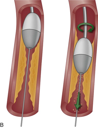
Percutaneous transluminal coronary angioplasty (PTCA) involves the use of a balloon-tipped catheter that, when advanced through an atherosclerotic lesion (atheroma), can be inflated intermittently for the purpose of dilating the stenotic area and improving blood flow through it (Fig. 16-12). The high inflation pressure of the balloon stretches the vessel wall, fractures the plaque, and enlarges the vessel lumen. After balloon deflation, the vessel exhibits some degree of elastic recoil, resulting in a residual stenosis of approximately 30%. A successful angioplasty procedure is one in which the stenosis is reduced to less than 50% of the vessel lumen diameter.44
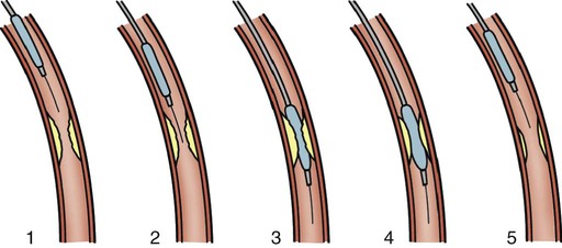
Although PTCA has relatively high success rates in initially opening occluded vessels, this technique by itself has major limitations, including the risk of acute vessel closure and a high frequency of restenosis. In the early application of angioplasty, acute closure occurred in up to 8% of patients as a result of dissection of the vessel wall and associated thrombus formation or vessel spasm. Restenosis occurred in more than one third of patients who underwent PTCA within the first 6 months and was diagnosed when patients experienced a recurrence of anginal symptoms.39 Studies showed that restenosis was influenced by the final lumen diameter achieved by the procedure, the severity of elastic recoil of the vessel walls in response to the balloon inflation, and the amount of intimal hyperplasia that occurred as the vessel healed over the treated area. Patient characteristics such as a history of diabetes or unstable angina were also found to increase the risk of restenosis.45
In the current era of PCI, design enhancements have led to low-profile catheters that are able to traverse tortuous anatomy and noncompliant balloons that prevent overdistention of the vessel.44 Another modification has been the cutting balloon—a device that produces incisions in the plaque before the balloon is dilated. Even with these improvements PTCA is rarely used alone as an intervention, except to treat lesions in very small coronary arteries.44 Nevertheless, balloon angioplasty remains an essential adjunctive technique in PCI for dilating vessels and for deploying intracoronary stents.
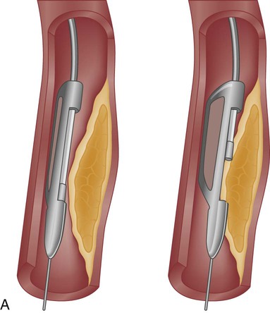
Atherectomy
Atherectomy is the excision and removal of the atherosclerotic plaque by cutting, shaving, or grinding. Two specialized coronary catheters are used in coronary intervention: directional coronary atherectomy (DCA) and rotational ablation (Rotablator). Initially, it was thought that removing (rather than compressing) the atherosclerotic plaque would decrease the rate of restenosis. Despite significant improvements in initial procedural success, atherectomy failed to significantly reduce the rate of restenosis. Atherectomy is useful for removing plaque in calcified or fibrotic lesions, which helps increase wall compliance and facilitate angioplasty and stent placement. In the current era, atherectomy devices are used in less than 5% of PCI procedures.44
Directional Coronary Atherectomy
The DCA catheter consists of a rotating, cup-shaped blade within a windowed cylindrical chamber on one side and a low-inflation balloon on the other. The catheter is positioned within the lesion, and the balloon is inflated, forcing the atheromatous plaque into the chamber window. The cutting blade is then used to shave the protruding plaque, which is collected within the chamber. The ability to turn the catheter in various directions within the vessel led to the name of the device. A DCA catheter is pictured in Figure 16-13A. Because DCA extracts pieces of atheroma that can be studied microscopically (rather like a biopsy specimen), it has contributed significantly to our understanding of atherosclerosis and restenosis.
Rotablator
The Rotablator device has a high-speed, rotating, diamond-coated bur that drills through the plaque, creating tiny particles (see Fig. 16-13B). The particulate matter is carried through the bloodstream and disposed of by the reticuloendothelial system. This is the most frequently used device to debulk heavily calcified lesions that cannot be dilated by angioplasty or prevent delivery of a coronary stent. Rotational atherectomy may also be used for chronic total occlusion and for calcified bifurcation lesions.44
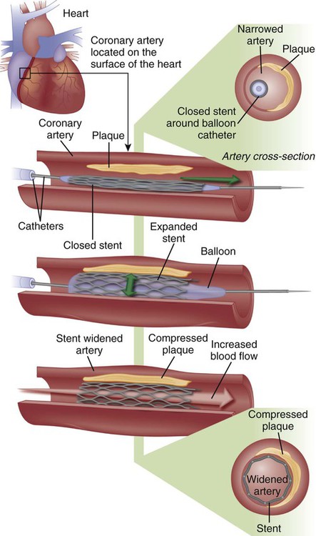
Coronary Stents
A major development in the field of interventional cardiology has been the coronary stent prosthesis. A stent is a metal structure that is introduced into the coronary artery over a guidewire and expanded into the vessel wall at the site of the lesion. Bare metal stents were first used to treat acute or threatened vessel closure after failed PTCA. The stent acted as a scaffold to tack dissection flaps against the vessel wall and provided mechanical support to minimize elastic recoil. Subsequent studies confirmed the clinical benefits of stents, which led to elective coronary stenting as a primary procedure. Stent implantation was initially limited to large vessels (greater than 3 mm) with proximal, discrete lesions. Improvements in stent design and operator technique allow for their deployment in smaller vessels with diffuse disease, vessels with lesions at bifurcations, and vessels with thrombus. Multiple stents may be implanted sequentially within a vessel to fully cover the area of the lesion. Stents are currently the predominant form of PCI and are used in more than 90% of all interventional procedures.44
Numerous stents are available. They are composed of various types of metal (stainless steel, titanium, cobalt chromium) and come in a variety of configurations (e.g., mesh, coil). Most stents are balloon expandable (Fig. 16-14).
Stent Thrombosis
Early use of stents was hampered by a high incidence of subacute stent thrombosis. This thrombosis tended to occur during the first 2 to 14 days after stent placement, and resulted in MI in the majority of cases.39 Later it was found that stent thrombosis was in part due to inadequate stent expansion within the vessel—which could be remedied by applying high-pressure balloon inflations within the stent during deployment. In addition, antiplatelet therapy was found to be more important than anticoagulation in preventing stent thrombosis.39 Because platelet activation is a complex process involving multiple pathways, combination therapy with two or more agents has proven most effective.46 The current standard of care for PCI typically includes dual antiplatelet therapy with aspirin and a thienopyridine. These oral agents are administered before the procedure and continued at discharge.47 Clopidogrel, a second-generation thienopyridine, has been studied extensively but may be ineffective in up to 26% of patients.39 Prasugrel is a newer third-generation thienopyridine that offers a faster onset of action, higher levels of platelet inhibition, and lower incidence of resistance.48 Recently the FDA approved a novel antiplatelet agent, ticagrelor. Advantages of this agent in comparison to clopidogrel and prasugrel are its short half-life and reversible antiplatelet effect. Disadvantages include the need for twice-daily dosing and higher cost.48a A description of oral antiplatelet agents is provided in Table 16-5.
TABLE 16-5
PHARMACOLOGIC MANAGEMENT
Oral Antiplatelet Agents
| MEDICATION | DOSAGE | ACTION | SPECIAL CONSIDERATIONS |
| Aspirin | 81-325 mg | Inhibits synthesis of thromboxane A2 resulting in irreversible inhibition of platelet activation | Lower doses are recommended when given with other antithrombotics |
| Clopidogrel (Plavix) | 300-600 mg loading dose 75-150 mg maintenance |
Irreversibly inhibits the ADP P2Y12 platelet receptor to block platelet activation | Onset of action 2-4 hr Should be held 5-7 days before elective surgery to decrease risk of bleeding Some patients may have a genetic resistance to clopidogrel, resulting in inadequate platelet inhibition |
| Prasugrel (Effient) | 60 mg loading dose 10 mg daily maintenance |
Irreversibly inhibits the ADP P2Y12 platelet receptor to block platelet activation | Onset of action 15-30 minutes Should be held 5-7 days before elective surgery to decrease risk of bleeding Contraindicated in patients with prior TIA or stroke; not recommended in patients >75 years of age |
| Ticagrelor (Brilinta) | 180 mg loading dose 90 mg twice daily maintenance |
Reversibly inhibits the ADP P2Y12 platelet receptor to block platelet activation | Onset of action 30 minutes Should be held 5 days before elective surgery to decrease risk of bleeding Contraindicated in patients with a history of ICH or severe hepatic impairment Maintenance aspirin dose above 100 mg reduces effectiveness |
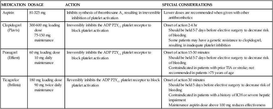
ADP, Adenosine diphosphate; ICH, intracranial hemorrhage; TIA, transient ischemic attack.
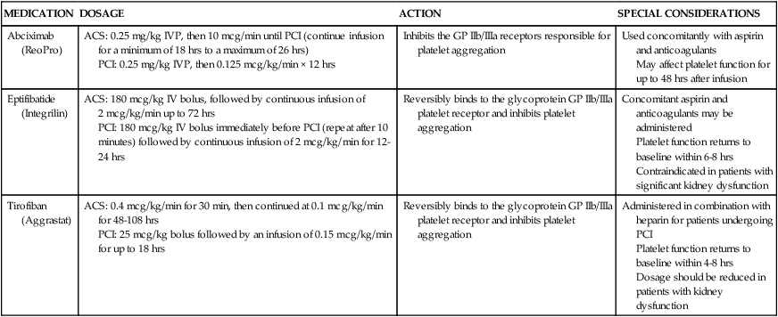
More potent intravenous antiplatelet agents—glycoprotein IIb/IIIa inhibitors—may also be used during PCI procedures, especially in high-risk patients.47 These medications act on the glycoprotein IIb/IIIa receptors on the platelet membrane to inhibit the final phase of platelet aggregation and prevent platelets from binding with fibrinogen. Abciximab (ReoPro) was the first of the glycoprotein IIb/IIIa inhibitors to be approved by the U.S. Food and Drug Administration (FDA) as an adjunct to PTCA for the prevention of abrupt closure of arteries in high-risk patients. Later, two additional agents, eptifibatide (Integrilin) and tirofiban (Aggrastat), were approved. A description of intravenous antiplatelet agents is provided in Table 16-6.
TABLE 16-6
PHARMACOLOGIC MANAGEMENT
Intravenous Antiplatelet Agents
| MEDICATION | DOSAGE | ACTION | SPECIAL CONSIDERATIONS |
| Abciximab (ReoPro) | ACS: 0.25 mg/kg IVP, then 10 mcg/min until PCI (continue infusion for a minimum of 18 hrs to a maximum of 26 hrs) PCI: 0.25 mg/kg IVP, then 0.125 mcg/kg/min × 12 hrs |
Inhibits the GP IIb/IIIa receptors responsible for platelet aggregation | Used concomitantly with aspirin and anticoagulants May affect platelet function for up to 48 hrs after infusion |
| Eptifibatide (Integrilin) | ACS: 180 mcg/kg IV bolus, followed by continuous infusion of 2 mcg/kg/min up to 72 hrs PCI: 180 mcg/kg IV bolus immediately before PCI (repeat after 10 minutes) followed by continuous infusion of 2 mcg/kg/min for 12-24 hrs |
Reversibly binds to the glycoprotein GP IIb/IIIa platelet receptor and inhibits platelet aggregation | Concomitant aspirin and anticoagulants may be administered Platelet function returns to baseline within 6-8 hrs Contraindicated in patients with significant kidney dysfunction |
| Tirofiban (Aggrastat) | ACS: 0.4 mcg/kg/min for 30 min, then continued at 0.1 mcg/kg/min for 48-108 hrs PCI: 25 mcg/kg bolus followed by an infusion of 0.15 mcg/kg/min for up to 18 hrs |
Reversibly binds to the glycoprotein GP IIb/IIIa platelet receptor and inhibits platelet aggregation | Administered in combination with heparin for patients undergoing PCI Platelet function returns to baseline within 4-8 hrs Dosage should be reduced in patients with kidney dysfunction |
In-Stent Restenosis
Bare metal stents have been shown to decrease the incidence of restenosis when compared with balloon angioplasty, most likely as a result of achieving the largest possible lumen diameter at the time of the intervention.44 Stents have not, however, proved to be a cure for restenosis as was once hoped. Restenosis within the stent is caused by intimal hyperplasia and can occur in a diffuse pattern throughout the stent, as discrete lesions within the body of the stent, or at the stent margins. The incidence of in-stent restenosis requiring intervention is approximately 20% within the first 6 months after implantation of a bare metal stent.45 Factors that increase the risk of in-stent restenosis are listed in Box 16-15.
Drug-Eluting Stents
In an effort to minimize restenosis, drug-eluting stents (DES) were developed. These stents have polymer coatings impregnated with medications that are released slowly into the endothelium at the site of stent placement to inhibit cellular proliferation. DES coated with sirolimus (an immunosuppressive medication used to prevent organ transplant rejection) and paclitaxel (an anticancer agent) have been approved by the FDA.45 In initial trials, DES were found to decrease the 6-month restenosis rate to less than 10%, and they soon became the predominant stent, implanted in 90% of patients. Later trials demonstrated similar efficacy between bare metal stents and DES in long-term outcomes (stent thrombosis, MI, or death) and raised concerns regarding the possibility of late stent thrombosis (greater than 1 year) in DES.39 As a result, DES usage has decreased somewhat to around 75% of patients.45 Because a DES delays endothelialization, dual antiplatelet therapy must be continued for a longer period to prevent stent thrombosis. A DES is also considerably more expensive than a bare metal stent. A comparison of bare metal stents and DES is provided in Table 16-7.
TABLE 16-7
COMPARISON OF BARE METAL AND DRUG-ELUTING STENTS
| CHARACTERISTICS | BARE METAL STENT | DRUG-ELUTING STENT |
| Restenosis rate (at 6 months) | 15%-20% | 5%-10% |
| Cost | $ | $$$ |
| Duration of dual antiplatelet therapy | Minimum of 1 month for non-ACS patients, at least 12 months for stents implanted for ACS | Minimum of 12 months for either non-ACS or ACS patients, and longer if tolerated |
| Recommended lesion features | Short lesions <20 mm Large vessel diameter >3 mm |
Longer lesions >20 mm Small vessel diameter <3.5 mm |
Future Research
Current DES are coated with permanent polymers that remain after the medication is released. These polymers are thought to cause inflammation and may lead to impaired endothelialization.45 Stent research is now focused on polymers that would dissolve once the stent-medication was released, leaving a bare metal stent in the vessel. Another area of research is a biodegradable stent that would provide an initial scaffolding to hold the vessel open, and then dissolve leaving only the healed vessel. Both of these options could potentially reduce the need for long-term antiplatelet therapy.39
Procedure
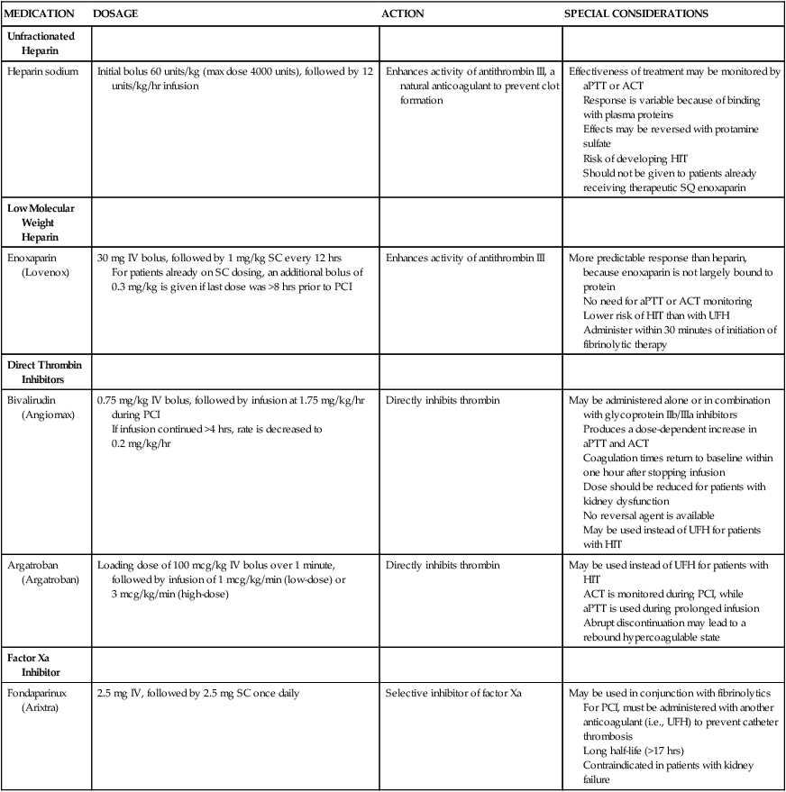
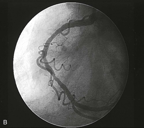
PCI is performed in the cardiac catheterization laboratory under fluoroscopy. Patients typically receive antiplatelet therapy (a thienopyridine and aspirin) before beginning the procedure. An introducer catheter, or sheath, is inserted percutaneously into the femoral artery. Alternatively, access to the arterial system can be obtained through the radial or brachial artery. In some cases, a venous sheath is inserted and used to perform a right-heart catheterization or to insert a pacing catheter, or both. A catheter with pacing capabilities may be indicated if dilation of the right coronary artery or circumflex artery is anticipated, because the blood supply to the conduction system of the heart may be interrupted, requiring emergency pacing. The patient is systemically anticoagulated to prevent clots from forming on or in any of the catheters. Unfractionated heparin has been used traditionally, initiated with a weight-based bolus and then titrated to achieve a target activated clotting time. Other anticoagulants may be selected based on physician preference or if the patient cannot tolerate heparin. Several of these newer agents have been shown to decrease the risk of bleeding complications when compared to UFH.49 Options for anticoagulant agents are described in Table 16-8. A special guiding catheter, designed to engage the coronary ostia, is inserted through the arterial sheath and advanced in a retrograde manner through the aorta. Nitroglycerin or calcium channel blockers may be given at this time to prevent coronary artery spasm and to maximize coronary vasodilation during the procedure. A guidewire is then advanced down the coronary artery and negotiated across the occluding atheroma. The balloon catheter is advanced over this guidewire and positioned across the lesion. The balloon is inflated and deflated repetitively until evidence of dilation is demonstrated on an angiogram (Fig. 16-15). For lesions that do not respond well to angioplasty, additional plaque removal may be done with an atherectomy device.
TABLE 16-8
PHARMACOLOGIC MANAGEMENT
Anticoagulants
| MEDICATION | DOSAGE | ACTION | SPECIAL CONSIDERATIONS |
| Unfractionated Heparin | |||
| Heparin sodium | Initial bolus 60 units/kg (max dose 4000 units), followed by 12 units/kg/hr infusion | Enhances activity of antithrombin III, a natural anticoagulant to prevent clot formation | Effectiveness of treatment may be monitored by aPTT or ACT Response is variable because of binding with plasma proteins Effects may be reversed with protamine sulfate Risk of developing HIT Should not be given to patients already receiving therapeutic SQ enoxaparin |
| Low Molecular Weight Heparin | |||
| Enoxaparin (Lovenox) | 30 mg IV bolus, followed by 1 mg/kg SC every 12 hrs For patients already on SC dosing, an additional bolus of 0.3 mg/kg is given if last dose was >8 hrs prior to PCI |
Enhances activity of antithrombin III | More predictable response than heparin, because enoxaparin is not largely bound to protein No need for aPTT or ACT monitoring Lower risk of HIT than with UFH Administer within 30 minutes of initiation of fibrinolytic therapy |
| Direct Thrombin Inhibitors | |||
| Bivalirudin (Angiomax) | 0.75 mg/kg IV bolus, followed by infusion at 1.75 mg/kg/hr during PCI If infusion continued >4 hrs, rate is decreased to 0.2 mg/kg/hr |
Directly inhibits thrombin | May be administered alone or in combination with glycoprotein IIb/IIIa inhibitors Produces a dose-dependent increase in aPTT and ACT Coagulation times return to baseline within one hour after stopping infusion Dose should be reduced for patients with kidney dysfunction No reversal agent is available May be used instead of UFH for patients with HIT |
| Argatroban (Argatroban) | Loading dose of 100 mcg/kg IV bolus over 1 minute, followed by infusion of 1 mcg/kg/min (low-dose) or 3 mcg/kg/min (high-dose) | Directly inhibits thrombin | May be used instead of UFH for patients with HIT ACT is monitored during PCI, while aPTT is used during prolonged infusion Abrupt discontinuation may lead to a rebound hypercoagulable state |
| Factor Xa Inhibitor | |||
| Fondaparinux (Arixtra) | 2.5 mg IV, followed by 2.5 mg SC once daily | Selective inhibitor of factor Xa | May be used in conjunction with fibrinolytics For PCI, must be administered with another anticoagulant (i.e., UFH) to prevent catheter thrombosis Long half-life (>17 hrs) Contraindicated in patients with kidney failure |

In most procedures, vessel dilation is followed by deployment of an intracoronary stent. A stent is positioned at the target site, the stent is expanded, and the catheter is removed, leaving the stent in place. Intravascular ultrasound is used by some clinicians to evaluate the vessel lumen diameter after stent deployment to ensure optimal expansion.41 Information obtained by ultrasonography provides a better estimate of residual plaque than that provided by angiography, because contrast material may surround the lattice-work of the stent, giving the appearance of a large lumen even when the stent is not fully open. The patient is transferred to the coronary care or angioplasty unit after the procedure for care and observation. Heparin or other anticoagulants are usually discontinued immediately after the procedure, to facilitate early sheath removal. Sheaths are removed when the activated clotting time (ACT) returns to normal in heparinized patients, or sooner if other anticoagulants or a vascular closure device is used. If glycoprotein IIb/IIIa inhibitors were initiated during the procedure, they may be continued for 12 to 24 hours, depending on the agent used. Dual antiplatelet therapy with aspirin and a thienopyridine (clopidogrel, prasugrel or ticagrelor) is routinely prescribed at discharge. Recommendations for thienopyridine administration vary based on the type of stent used (see Table 16-7), whereas aspirin is continued indefinitely.
Acute Complications
The incidence of serious cardiac complications after PCI, including coronary spasm, coronary artery dissection, and acute coronary thrombosis, has decreased significantly with improvements in technology. Stents have proved efficacious in the repair of coronary dissections, decreasing the need for emergency bypass surgery. Acute thrombosis has decreased with the established use of dual antiplatelet agents. Bleeding and hematoma formation at the site of vascular cannulation, compromised blood flow to the involved extremity, and retroperitoneal bleeding with femoral access occur infrequently, but are associated with increased morbidity and lengthened hospitalization.50 Other complications that can occur in the period immediately after PCI include contrast-induced kidney failure, dysrhythmias, and vasovagal response (hypotension, bradycardia, and diaphoresis) during manipulation or removal of introducer sheaths.
Late Complications
Restenosis after PCI continues to be a problem, although rates are much lower with DES than with angioplasty alone. Patients at greatest risk are those with complex lesions, multivessel disease, or diabetes.45 Treatment options for in-stent restenosis include balloon dilation, debulking with an atherectomy device, implantation of another DES or brachytherapy—the localized delivery of intracoronary radiation through specialized catheters. Because healing within the stent is delayed, late thrombosis may occur in patients with DES. Late thrombosis, although rare, is associated with a 45% mortality rate. Premature discontinuation of antiplatelet therapy is the strongest predictor of late stent thrombosis, especially with DES.45
Nursing Management
Nursing management and nursing diagnoses after PCI focus on accurate assessment of the patient’s condition and prompt intervention (Box 16-16). The nurse at the bedside is in a unique position to continuously monitor for clinical manifestations of potential problems and to take quick and appropriate action to minimize the deleterious effects of complications related to the interventional catheter procedure.
 Box 16-16 Nursing Diagnoses
Percutaneous Transluminal Coronary Angioplasty, Coronary Atherectomy, and Stenting
• Risk for Decreased Cardiac Tissue Perfusion, p. 1155
• Risk for Ineffective Peripheral Tissue Perfusion, p. 1158
• Activity Intolerance related to prolonged immobility or deconditioning, p. 1119
• Acute Pain related to transmission and perception of cutaneous, visceral, muscular, or ischemic impulse, p. 1123
• Anxiety related to threat to biologic, psychological, or social integrity, p. 1125
• Deficient Knowledge related to lack of previous exposure to information, p. 1134 (see Box 16-18, Patient Education for Percutaneous Transluminal Coronary Angioplasty, Coronary Atherectomy, and Stenting)
Prevention of Contrast Induced Acute Kidney Injury
Patients undergoing PCI are exposed to significant amounts of contrast dye, with its associated nephrotoxicity. Protective strategies may be implemented before the procedure, especially for patients with evidence of baseline kidney impairment. This may include preprocedural hydration and infusion of sodium bicarbonate.51 While an early study indicated that administration of N-acetylcysteine (Mucomyst) might be beneficial, current guidelines do not recommend it for prevention of contrast-induced acute kidney injury.41 After PCI, hydration is important to maintain adequate flow through the kidneys. Intravenous fluids are administered, and patients are encouraged to take oral fluids as tolerated.
Vascular Site Care
Peripheral ischemia can also occur secondary to cannulation of the vessel, so nursing care includes frequent assessment of the adequacy of circulation to the involved extremity (Box 16-17). The patient is instructed to keep the limb straight and minimize movement. Additional activity restrictions vary depending on the size and location of the sheath, type of anticoagulation prescribed, methods used to achieve hemostasis, and institutional protocols. For femoral access, the head of the bed is not elevated more than 30 degrees while the sheath is in place (to prevent dislodgment) and for a period of time after its removal (to prevent bleeding). For brachial or radial access, a splint may be used to prevent flexion of the arm or wrist. After sheath removal, direct pressure is applied to the puncture site for 15 to 30 minutes until hemostasis is achieved. If direct pressure is inadequate or the patient is at higher risk for bleeding, a C-clamp or other compression device may be used to apply continuous pressure for 1 to 2 hours to ensure adequate hemostasis. Patients usually are allowed to resume ambulation 2 to 6 hours after the procedure, or sooner if a vascular closure device is employed.52
 Box 16-17
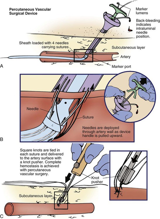
In the last decade, a number of products have been introduced to facilitate adequate hemostasis at the femoral access site after sheath removal. Active closure devices utilize mechanical sutures, collagen plugs, or metal clips to close the vessel when the sheath is removed. Advantages of these devices include a reduced time to hemostasis (under than 5 minutes) regardless of the patient’s level of anticoagulation, earlier ambulation, and increased patient comfort.50 The Perclose closure device contains needles and sutures that are used to suture the artery closed after the interventional procedure (Fig. 16-16). Angio-Seal is a vascular hemostatic device that uses a collagen plug to seal the arterial puncture site. Gentle pressure is maintained over the puncture site for approximately 5 minutes, until hemostasis is achieved. The StarClose vascular closure device consists of a tiny circumferential nitinol (nickel and titanium) clip that is applied to surface of the vessel to close the femoral artery at the end of the procedure.
Reports of complications and increased cost have limited the use of active closure devices.50,53 To avoid these complications, a number of products have been developed to enhance manual compression and shorten the time required to achieve hemostasis. Some of these devices rely on the delivery of prothrombotic materials by a patch, whereas others increase local pressure over the puncture site. These devices do not offer immediate closure, but may decrease the time to ambulation.50 A comparison of vascular closure systems is provided in Table 16-9.
TABLE 16-9
| TECHNOLOGY AND EXAMPLES | DESCRIPTION | COMMENTS |
| Patch | ||
| Chito-Seal Clo-Sur P.A.D. D-Stat Syvek Patch |
Patches that contain materials to promote clotting are applied directly to the puncture site, along with manual compression. | Less expensive than active closure devices No foreign material is left in the patient |
| Suture | ||
| Perclose A-T ProGlide |
Sutures deployed through the sheath are used to close the arteriotomy site. | Allows for immediate reaccess through the site if needed (see Fig. 16-16) Device failure may require surgical repair |
| Plug or Sealant | ||
| Angio-Seal Duett Mynx |
Placement of a procoagulant sealant such as collagen or thrombin is used to close the artery. Angio-Seal also includes an intravascular suture to anchor the collagen plug in place. The Mynx system uses a balloon catheter to inject sealant into the puncture site tract. | Reaccess must be done 1 cm above the previous arterial access site to avoid dislodging the sealant Extrusion of the sealant into the vessel may compromise the arterial lumen Components are absorbed within 30-90 days, depending on the sealant used |
| Clip or Staple | ||
| EVS-Angiolink StarClose |
Circumferential staples or clips are deployed at the site of the arteriotomy to close the vessel. | Extravascular clip does not compromise the artery lumen |
Patient Education
In most cases, patients undergoing elective angioplasty, atherectomy, or stent procedures are hospitalized for approximately 24 hours. All patients require education about their medication regimen and about risk-factor modification (Box 16-18). Because of the abbreviated hospital stay, the nurse often has time to do little more than identify the offending risk factors and initiate basic instruction. Patients are referred to local cardiac rehabilitation centers for more extensive teaching and follow-up to facilitate understanding and compliance with risk-factor modification.
Another point of instruction that must be addressed is the patient’s knowledge deficit related to discharge medications. Patients are sent home on a regimen of antiplatelet medications and medications for secondary prevention, such as lipid-lowering agents and blood pressure medications. A nitrate such as isosorbide may be prescribed to promote vasodilation, or, if the patient has demonstrated evidence of a vasospastic component to the disease, calcium channel blockers may be used. It is essential that the patient clearly understands the rationale for therapy and the potential side effects of each medication. Patients also need to understand the importance of not discontinuing their antiplatelet therapy; deaths have been reported when patients discontinued this therapy before elective procedures.46 It is important that patients be provided with written information and a number to call if problems occur.
Percutaneous Valve Repair
Balloon Valvuloplasty
Percutaneous catheter technology has also been adapted to allow for nonsurgical interventions for stenotic cardiac valves. Current guidelines recommend balloon aortic valvuloplasty for adults only as a bridge to surgery for patients with unstable hemodynamics and who are at a high risk for AVR or in patients with aortic stenosis who are not surgical candidates.54 Balloon aortic valvuloplasty has a limited role in adults, because restenosis and clinical deterioration occur within 6 to 12 months in most patients, and there has been no significant difference in long-term survival shown between it and medical therapy alone.55,56
Balloon valvuloplasty is performed in the cardiac catheterization laboratory by placing a balloon across the stenotic valve and inflating it to reduce stenosis.57 Regurgitant flow can result, particularly after mitral valvuloplasty, and may result in the need for emergent valve replacement if severe. The risks of balloon valvuloplasty are similar to those inherent in most catheterization procedures and include cardiac perforation, thromboembolic events, dysrhythmias, and vascular complications caused by the sheath. Postprocedural nursing management is similar to that for other percutaneous cardiac catheter procedures.
Transcatheter Aortic Valve Replacement
Transcatheter aortic valve replacement (TAVR) is a transformational therapy for patients who have severe aortic stenosis but who are extremely high-risk surgical candidates or who are inoperable by virtue of associated comorbidities.55 TAVR can be done with spinal or general anesthesia in a cardiac catheterization lab or in a hybrid operating room. Transcatheter aortic valves are bioprosthetic valves that are loaded onto a stent or frame, which are then expanded to anchor the valve in the aortic annulus with no sutures required.57 Different approaches are used to deploy the device, but once it is in place, contrast medium is used to ensure correct positioning of the catheter valve across the aortic annulus.57
While TAVR has been shown to have excellent clinical outcomes in high-risk patients, complications are fairly common due to the complexity of the procedure and the morbidity of the patients. Vascular complications are the most frequent adverse outcome of TAVR, especially with the transfemoral approach due to the large-caliber sheaths and severe atherosclerosis of the arteries.55 The incidence of early ischemic stroke (within the first 30 days) and need for permanent pacemakers postoperatively continues to be of major concern.58,59,60 Factors affecting regurgitation through the valve include the ratio of the valve size to the annulus size, positioning of the valve, and calcification of the native valve, all of which may contribute to mild or severe paravalvular aortic regurgitation.61 Postoperative assessment includes monitoring hemodynamics and fluid balance, observing for signs of stroke and kidney injury along with identifying rhythm disturbances that may require back-up pacing or medical interventions. Multiple comorbid diseases have usually made patients candidates for TAVR and thus nursing care must focus on preventing complications associated with these conditions.57
[/level-membership-for-critical-care-medicine-category][not-level-membership-for-critical-care-medicine-category]
Cardiovascular Therapeutic Management
Pacemakers
Pacemakers are electronic devices that can be used to initiate the heartbeat when the heart’s intrinsic electrical system cannot effectively generate a rate adequate to support cardiac output. Pacemakers may be used temporarily, either supportively or prophylactically, until the condition responsible for the rate or conduction disturbance resolves. They also may be used on a permanent basis if the patient’s condition persists despite adequate therapy. The use of permanent pacemakers as a form of device-based therapy has expanded significantly in the last decade.1
Indications for Temporary Pacing
The clinical indications for instituting temporary pacemaker therapy are similar regardless of the cause of the rhythm disturbance that necessitates the placement of a pacemaker (Box 16-1). The causes range from ischemia and electrolyte imbalances to sequelae related to acute myocardial infarction (MI) or cardiac surgery.
Diagnostic Indications
Several diagnostic uses for temporary pacing have evolved. Electrophysiology studies (EPS) are performed in cardiac catheterization laboratories equipped with specialized pacing equipment. During an EPS, catheters with pacing electrodes are used to diagnose the patient’s potential for dysrhythmias.2 These electrodes are used to induce dysrhythmias in patients with recurrent symptomatic tachydysrhythmias. This allows the physician to closely evaluate the particular dysrhythmia and determine appropriate therapy. For those patients whose tachydysrhythmia is found to be refractory to conventional antidysrhythmic therapy, radiofrequency (RF) current catheter ablation of the responsible tissue can be done safely and effectively in the electrophysiology laboratory. After a mapping procedure has localized the site of dysrhythmia formation, short bursts of RF current are delivered through the catheter, destroying the offending tissue with heat. Ablation has been shown to be an effective treatment for patients with symptomatic supraventricular tachycardias that result from atrioventricular (AV) node re-entry or accessory pathways, such as Wolff-Parkinson-White syndrome.3,4 Catheter ablation may also be used as a therapeutic strategy for selected patients with atrial fibrillation.5
Intracardiac electrograms—recordings of cardiac electrical activity obtained from pacing electrodes—may provide useful diagnostic information. The atrial electrogram (AEG) is an amplified recording of atrial activity that can be obtained through the use of an atrial pacing electrode or an esophageal pill electrode and a standard electrocardiogram (ECG) machine. It may be used after cardiac surgery to facilitate the diagnosis of supraventricular dysrhythmias in patients with temporary atrial epicardial wires already in place.6
The Pacemaker System
Pacing Lead Systems
The bipolar lead used in transvenous pacing has two electrodes on one catheter (Fig. 16-1). The distal, or negative, electrode is at the tip of the pacing lead and is in direct contact with the heart, usually inside the right atrium or ventricle. Approximately 1 cm from the negative electrode is a positive electrode. The negative electrode is attached to the negative terminal, and the positive electrode is attached to the positive terminal of the pulse generator, either directly or by means of a bridging cable (see Fig. 16-1B).
A unipolar pacing system (epicardial or transvenous) has only one electrode (the negative electrode) making contact with the heart. For a permanent pacemaker, the positive electrode can be created by the metallic casing of the subcutaneously implanted pulse generator (Fig. 16-2), or as is the case with a unipolar epicardial lead system, the positive electrode can be formed by a piece of surgical steel wire sewn into the subcutaneous tissue of the chest or the metal portion of a surface ECG electrode.
Because the unipolar pacing system has a wide sensing area as a result of the relatively long distance between the negative and positive electrodes, it has better sensing capabilities than does a bipolar system. However, this feature makes the unipolar system more susceptible to sensing extraneous signals, such as the electrical artifacts created by normal muscle movements (i.e., myopotentials) or by external electromagnetic interference (EMI), which may result in inappropriate inhibition of the pacing stimulus. This problem is of more concern in permanent pacing systems, in which the “can” of the pacemaker generator may be used as a part of the pacing circuit. Because the can is located near a large muscle mass, upper body movement can result in the inappropriate sensing of myopotentials.7
Pacing Routes
Several routes are available for temporary cardiac pacing (Box 16-2). Permanent pacing usually is accomplished transvenously, although when a thoracotomy is otherwise indicated, as in cardiac surgery, the physician may elect to insert permanent epicardial pacing wires.
Transcutaneous cardiac pacing involves the use of two large skin electrodes, one placed anteriorly and the other posteriorly on the chest, connected to an external pulse generator. It is a rapid, noninvasive procedure that nurses can perform in the emergency setting and is recommended in the advanced cardiac life support (ACLS) algorithm for the treatment of symptomatic bradycardia that does not respond to atropine.8 Improved technology related to stimulus delivery and the development of large electrode pads that help disperse the energy have helped reduce the pain associated with cutaneous nerve and muscle stimulation. Discomfort may still be an issue for some patients, particularly when higher energy levels are required to achieve capture. This route is typically used as a short-term therapy until the situation resolves or another route of pacing can be established.
The insertion of temporary epicardial pacing wires has become a routine procedure during most cardiac surgical cases. Ventricular and, in many cases, atrial pacing wires are loosely sewn to the epicardium. The terminal pins of these wires are pulled through the skin before the chest is closed. If both chambers have pacing wires attached, the atrial wires exit subcostally to the right of the sternum and the ventricular wires exit in the same region but to the left of the sternum. These wires can be removed several days after surgery by gentle traction at the skin surface with minimal risk of bleeding.9
Five-Letter Pacemaker Codes
In the 1960s, pacemaker terminology was limited to fixed-rate and demand pacing; AV sequential pacing was introduced in the early 1970s. Although these terms are still useful for understanding pacemaker function (Box 16-3), the continued expansion of functional capabilities of pulse generators has made it necessary to develop a more precise classification system. In 1974, the Inter-Society Commission for Heart Disease (ICHD) adopted a three-letter code for describing the various pacing modalities available. The code has since undergone several revisions, including the addition of two more letters representing programming characteristics and multisite pacing functions, to accommodate the development of newer devices that are rate responsive or that pace from more than one site within the atria and the ventricles. Table 16-1 describes the current five-letter code.10 The original three-letter code remains adequate to describe temporary pacemaker function.
TABLE 16-1
| POSITION I: CHAMBERS PACED | POSITION II: CHAMBERS SENSED | POSITION III: RESPONSE TO SENSING | POSITION IV: RATE MODULATION | POSITION V: MULTISITE PACING |
| 0 = None | 0 = None | 0 = None | 0 = None | 0 = None |
| A = Atrium | A = Atrium | T = Triggered | R = Rate Modulation | A = Atrium |
| V = Ventricle | V = Ventricle | I = Inhibited | V = Ventricle | |
| D = Dual (A + V) | D = Dual (A + V) | D = Dual (T + I) | D = Dual (A + V) |
Modified from Bernstein AD, et al. The Revised NASPE/BPEG generic pacemaker code for antibradycardia, adaptive-rate and multisite pacing. PACE. 2002;25:260.
The original code is based on three categories, each represented by a letter. The first letter refers to the cardiac chamber that is paced. The second letter designates which chamber is sensed, and the third letter indicates the pacemaker’s response to the sensed event. These three letters are used to describe the mode of pacing. For example, a VVI pacemaker paces the ventricle when the pacemaker fails to sense an intrinsic ventricular depolarization, but sensing of a spontaneous ventricular depolarization inhibits ventricular pacing. A VOO pacemaker paces the ventricle at a fixed rate and has no sensing capabilities. In DDD pacing, atrial and ventricular leads are used for pacing and sensing. In response to sensed activity, the pacemaker inhibits the pacing stimulus; a sensed P wave in the atrium inhibits the atrial spike, and a sensed R wave in the ventricle inhibits the ventricular pacing spike. A sensed P wave may also be used to trigger a ventricular pacing stimulus if normal conduction through the AV node is impaired. Table 16-2 provides a description of temporary pacing modes.
TABLE 16-2
EXAMPLES OF TEMPORARY PACING MODES
| PACING MODE | DESCRIPTION |
| Asynchronous | |
| AOO | Atrial pacing, no sensing |
| VOO | Ventricular pacing, no sensing |
| DOO | Atrial and ventricular pacing, no sensing |
| Synchronous | |
| AAI | Atrial pacing, atrial sensing, inhibited response to sensed P waves |
| VVI | Ventricular pacing, ventricular sensing, inhibited response to sensed QRS complexes |
| DVI | Atrial and ventricular pacing, ventricular sensing; both atrial and ventricular pacing are inhibited if a spontaneous ventricular depolarization is sensed |
| DDD | Both chambers are paced and sensed; inhibited response of the pacing stimuli to sensed events in their respective chambers; triggered response to sensed atrial activity to allow for rate-responsive ventricular pacing |
Physiologic pacing has traditionally been used to describe modes in which the normal physiologic, or sequential, relationship between atrial and ventricular stimulation and contraction is maintained. AV synchrony increases the volume in the ventricle before contraction and helps to improve cardiac output. This may be achieved with atrial pacing in patients who have an intact conduction system or by dual chamber pacing when atrial-to-ventricular conduction is impaired (i.e., during heart block). More recently, physiologic pacing has evolved to include the maintenance of ventricular synchrony as well. Strategies to achieve this include minimizing the use of ventricular pacing and simultaneous pacing of both right and left ventricles.1
Pacemaker Settings
The rate control (Fig. 16-3) regulates the number of impulses that can be delivered to the heart per minute. The rate setting depends on the physiologic needs of the patient, but it usually is maintained between 60 and 80 beats/min. Pacing rates for overdrive suppression of tachydysrhythmias may greatly exceed these values. Some generators have special controls for overdrive pacing that allow for rates of up to 800 stimuli per minute. If the pacemaker is operating in a dual-chamber mode, the ventricular rate control also regulates the atrial rate.
The output dial regulates the amount of electrical current, measured in milliamperes (mA), that is delivered to the heart to initiate depolarization. The point at which depolarization occurs, called threshold, is indicated by a myocardial response to the pacing stimulus (i.e., capture). Threshold can be determined by gradually decreasing the output setting until 1 : 1 capture is lost. The output setting is then slowly increased until 1 : 1 capture is re-established; this threshold to pace is less than 1 mA with a properly positioned pacing electrode. The output is set two to three times higher than threshold, because thresholds tend to fluctuate over time. Box 16-4 details the procedure for measuring pacing thresholds. Separate output controls for atrium and ventricle are used with a dual-chamber pulse generator.
The sensitivity control regulates the ability of the pacemaker to detect the heart’s intrinsic electrical activity. Sensitivity is measured in millivolts (mV) and determines the size of the intracardiac signal that the generator will recognize. If the sensitivity is adjusted to its most sensitive setting—a setting of 0.5 to 1 mV—the pacemaker can respond even to low-amplitude electrical signals coming from the heart. Turning the sensitivity to its least sensitive setting (i.e., adjusting the dial to a setting of 20 mV or to the area labeled async) results in inability of the pacemaker to sense any intrinsic electrical activity and causes the pacemaker to function at a fixed rate. A sense indicator (often a light) on the pulse generator signals each time intrinsic cardiac electrical activity is sensed. A pulse generator may be designed to sense atrial activity or ventricular activity, or both. Box 16-5 describes the procedure for measuring sensitivity. The sensitivity is set at half of the value of the sensitivity threshold to ensure that all appropriate intrinsic cardiac signals are sensed. For example, if the measured sensitivity threshold is 3.0 mV, the generator is set at 1.5 mV. The pacemaker’s sensing ability can be quickly evaluated by observing for a change in pacing rhythm in response to spontaneous depolarizations.
Temporary dual chamber pacemakers have other settings that are required in the DDD mode (see Fig. 16-3B). The lower rate, or base rate, determines the rate at which the generator will pace when intrinsic activity falls below the set rate of the pacemaker. The upper rate determines the fastest ventricular rate the pacemaker will deliver in response to sensed atrial activity. This setting is needed to protect the patient’s heart from being paced in response to rapid atrial dysrhythmias. The pulse width, which can be adjusted from 0.05 to 2 msec, controls the length of time that the pacing stimulus is delivered to the heart. There also is an atrial refractory period, programmable from 150 to 500 msec, which regulates the length of time, after a sensed or paced ventricular event, during which the pacemaker cannot respond to another atrial stimulus. An emergency button is also available on most models to allow for rapid initiation of asynchronous (DOO) pacing during an emergency.
Pacing Artifacts
All patients with temporary pacemakers require continuous ECG monitoring. The pacing artifact is the spike that is seen on the ECG tracing as the pacing stimulus is delivered to the heart. A P wave is visible after the pacing artifact if the atrium is being paced (Fig. 16-4A). Similarly, a QRS complex follows a ventricular pacing artifact (see Fig. 16-4B). With dual-chamber pacing, a pacing artifact precedes both the P wave and the QRS complex (see Fig. 16-4C).
Not all paced beats look alike. For example, the artifact (spike) produced by a unipolar pacing electrode is larger than that produced by a bipolar lead (Fig. 16-5). The QRS complex of paced beats appears different, depending on the location of the pacing electrode. If the pacing electrode is positioned in the RV, a left bundle branch block (LBBB) pattern is displayed on the ECG. A right bundle branch block (RBBB) pattern is visible if the pacing stimulus originates from the left ventricle (LV).
Pacemaker Malfunctions
Pacing Abnormalities
Failure of the pacemaker to deliver the pacing stimulus results in disappearance of the pacing artifact, even if the patient’s intrinsic rate is less than the set rate on the pacer (Fig. 16-6). This can occur intermittently or continuously and can be attributed to failure of the pulse generator or its battery, a loose connection between the various components of the pacemaker system, broken lead wires, or stimulus inhibition as a result of EMI. Tightening connections, replacing the batteries or the pulse generator itself, or removing the source of EMI may restore pacemaker function.
If the pacing stimulus fires but fails to initiate a myocardial depolarization, a pacing artifact will be present but will not be followed by the expected P wave or QRS complex, depending on the chamber being paced (Fig. 16-7). This loss of capture most often can be attributed to displacement of the pacing electrode or to an increase in threshold (electrical stimulus necessary to elicit a myocardial depolarization) as a result of medications, metabolic disorders, electrolyte imbalances, or fibrosis or myocardial ischemia at the site of electrode placement. In many cases, increasing the output (mA) elicits capture. For transvenous leads, repositioning the patient onto the left side may improve lead contact and restore capture.
Pacing can occur at inappropriate rates. For example, impending battery failure in a permanent pacemaker can result in a gradual decrease in the paced rate, also referred to as rate drift. Inappropriate stimuli from a pacemaker may result in a pacemaker-mediated tachycardia. This usually is caused by sensing of inappropriate signals in a dual-chamber pacemaker that is in a trigger mode, such as DDD. The tachycardia can be terminated by placing a magnet over the generator to transiently suspend sensing.11
Sensing Abnormalities
Sensing abnormalities include both undersensing and oversensing.
Undersensing.
Undersensing is the inability of the pacemaker to sense spontaneous myocardial depolarizations. Undersensing results in competition between paced complexes and the heart’s intrinsic rhythm. This malfunction is manifested on the ECG by pacing artifacts that occur after or are unrelated to spontaneous complexes (Fig. 16-8). Undersensing can result in the delivery of pacing stimuli into a relative refractory period of the cardiac depolarization cycle (see Fig. 12-25 in Chapter 12). A ventricular pacing stimulus delivered into the downslope of the T wave (R-on-T phenomenon) is a real danger with this type of pacer aberration, because it may precipitate a lethal dysrhythmia. The nurse must act quickly to determine the cause and initiate appropriate interventions. Often, the cause can be attributed to inadequate wave amplitude (height of the P or R wave). If this is the case, the situation can be promptly remedied by increasing the sensitivity by moving the sensitivity dial toward its lowest setting. Other possible causes include inappropriate (asynchronous) mode selection, lead displacement or fracture, loose cable connections, and pulse generator failure.
Nursing Management
Prevention of Pacemaker Malfunction
It is important to be aware of all sources of EMI within the critical care environment that may interfere with the pacemaker’s function. Sources of EMI in the clinical area include electrocautery, defibrillation current, radiation therapy, magnetic resonance imaging devices, and transcutaneous electrical nerve stimulation (TENS) units.12 In most cases, if EMI is suspected of precipitating pacemaker malfunction, conversion to the asynchronous mode (fixed rate) can maintain pacing until the cause of the EMI is removed.
Microshock Protection
Because the pacing electrode provides a direct, low-resistance path to the heart, the nurse takes special care while handling the external components of the pacing system to avoid conducting stray electrical current from other equipment. Even a small amount of stray current transmitted through the pacing lead could precipitate a lethal dysrhythmia. The possibility of microshock can be minimized by wearing gloves when handling the pacing wires and by proper insulation of terminal pins of pacing wires when they are not in use (Box 16-6). The latter precaution can be accomplished by the use of caps provided by the manufacturer or by improvising with a plastic syringe or section of disposable rubber glove. The wires are taped securely to the patient’s chest to prevent accidental electrode displacement.
Box 16-6 Patient Safety Alert
Prevention of Microshock
• Wear gloves when handling pacing wires
• Secure all connections between pulse generator, pacing cable, and leads
• Insulate lead tips with nonconducting materials when not attached to generator (manufacturer’s cap, finger cot, plastic syringe)
• Keep dressings and pacing equipment dry
Patient Education
Patient teaching for the person with a temporary pacemaker emphasizes the prevention of complications (Box 16-7). The patient is instructed not to handle any exposed portion of the lead wire and to notify the nurse if the dressing over the insertion site becomes soiled, wet, or dislodged. The patient also is advised not to use any electrical devices brought in from home that could interfere with pacemaker functioning. Patients with temporary transvenous pacemakers need to be taught to restrict movement of the affected extremity to prevent lead displacement.
Permanent Pacemakers
Almost 400,000 permanent pacemakers are implanted annually in the United States, and critical care nurses are likely to encounter these devices in their clinical practice.13 These pacemakers were originally designed to provide an adequate ventricular rate in patients with symptomatic bradycardia. Today, the goal of pacemaker therapy is to simulate, as much as possible, normal physiologic cardiac depolarization and conduction. Sophisticated generators permit rate-responsive pacing, effecting responses to sensed atrial activity (DDD) or to a variety of physiologic sensors (body motion or minute ventilation). For patients who do not have a functional sinus node that can increase their heart rate, rate-responsive pacemakers may improve exercise capacity and quality of life.14 Table 16-3 describes the types of rate-responsive pacing generators in clinical use. The concept of physiologic pacing continues to evolve, because studies have indicated that pacing initiated from the RV apex—even in a dual-chamber mode—may promote heart failure in patients with permanent pacemakers.1 This has prompted further research to identify alternative sites for pacing and modes that can maximize intrinsic AV conduction and minimize ventricular pacing.15
TABLE 16-3
PERMANENT PACEMAKER RATE-RESPONSE PACING MODES
| PULSE GENERATOR | DESCRIPTION |
| AAIR | AAI features plus rate-responsive pacing; used for patients with a symptomatic bradycardia who have a paceable atrium and intact atrioventricular conduction |
| VVIR | VVI features plus rate-responsive pacing; used for patients with an atrium that is unpaceable as a result of chronic atrial fibrillation or other atrial dysrhythmia |
| DDDR | DDD features plus rate-responsive pacing; used for patients with a symptomatic bradycardia in which the atrium is paceable but atrioventricular conduction is, or may become, unreliable |
[/not-level-membership-for-critical-care-medicine-category]
