Objectives
• Describe the functions of a temporary pacemaker and an implantable cardioverter-defibrillator.
• Identify the signs of reperfusion in a patient undergoing fibrinolytic therapy.

Be sure to check out the bonus material, including free self-assessment exercises, on the Evolve web site at http://evolve.elsevier.com/Urden/priorities/.
A wide variety of therapeutic interventions is employed in the management of the patient with cardiovascular dysfunction. This chapter focuses on the priority interventions used to manage acute cardiovascular disorders in the critical care setting.
Temporary Pacemakers
Pacemakers are electronic devices that can be used to initiate the heartbeat when the heart’s intrinsic electrical system cannot effectively generate a rate adequate to support cardiac output. Pacemakers may be used temporarily, either supportively or prophylactically, until the condition responsible for the rate or conduction disturbance resolves.1
Indications
The clinical indications for instituting temporary pacemaker therapy are similar regardless of the cause of the rhythm disturbance that necessitates the placement of a pacemaker. The causes range from drug toxicities and electrolyte imbalances to sequelae related to acute myocardial infarction (MI) or cardiac surgery.
The Pacemaker System
A pacemaker system is a simple electrical circuit consisting of a pulse generator and a pacing lead (an insulated electrical wire) with one, two, or three electrodes.
Pacing Pulse Generator
The pulse generator is designed to generate an electrical current that travels through the pacing lead and exits through an electrode (exposed portion of the wire) that is in direct contact with the heart. This electrical current initiates a myocardial depolarization. The current then seeks to return by one of several pathways to the pulse generator to complete the circuit. The power source for a temporary external pulse generator is a standard 9-volt alkaline battery inserted into the generator.
Pacing Lead Systems
The pacing lead used for temporary pacing may be bipolar or unipolar. In a bipolar system, two electrodes (positive and negative) are located within the heart, whereas in a unipolar system, only one electrode (negative) is in direct contact with the myocardium. In both systems, the current flows from the negative terminal of the pulse generator, down the pacing lead to the negative electrode, and into the heart. The current is then picked up by the positive electrode (ground) and flows back up the lead to the positive terminal of the pulse generator.
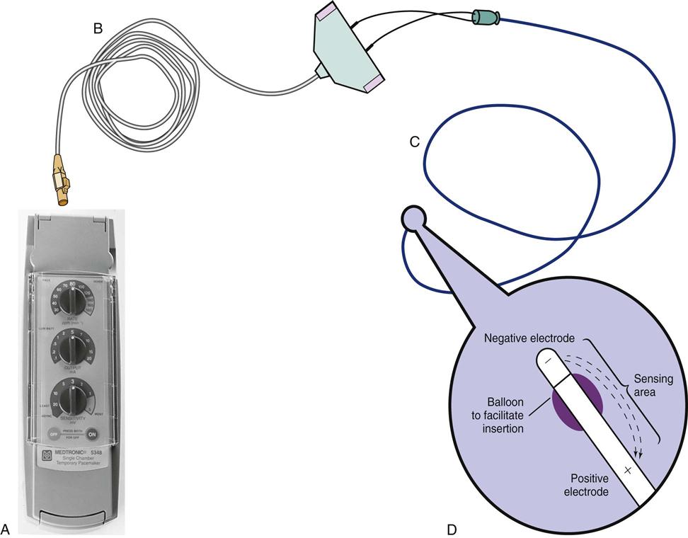
The bipolar lead used in transvenous pacing has two electrodes on one catheter (Figure 13-1). The distal, or negative, electrode is at the tip of the pacing lead and is in direct contact with the heart, usually inside the right atrium or ventricle. Approximately 1 cm from the negative electrode is a positive electrode. The negative electrode is attached to the negative terminal, and the positive electrode is attached to the positive terminal of the pulse generator, either directly or by means of a bridging cable (see Figure 13-1, B).
Pacing Routes
Several routes are available for temporary cardiac pacing. Permanent pacing usually is accomplished transvenously, although when a thoracotomy is otherwise indicated, as in cardiac surgery, the physician may elect to insert permanent epicardial pacing wires.
Transcutaneous Pacing
Transcutaneous cardiac pacing involves the use of two large skin electrodes, one placed anteriorly and the other posteriorly on the chest, connected to an external pulse generator. It is a rapid, noninvasive procedure that nurses can perform in the emergency setting and is recommended as a primary intervention in the advanced cardiac life support (ACLS) algorithm for the treatment of symptomatic bradycardia.2 Improved technology related to stimulus delivery and the development of large electrode pads that help disperse the energy have helped reduce the pain associated with cutaneous nerve and muscle stimulation. Discomfort may still be an issue for some patients, particularly when higher energy levels are required to achieve capture. This route is typically used as a short-term therapy until the situation resolves or another route of pacing can be established.
Epicardial Pacing
The insertion of temporary epicardial pacing wires has become a routine procedure during most cardiac surgical cases. Ventricular and, in many cases, atrial pacing wires are loosely sewn to the epicardium. The terminal pins of these wires are pulled through the skin before the chest is closed. If both chambers have pacing wires attached, the atrial wires exit subcostally to the right of the sternum and the ventricular wires exit in the same region but to the left of the sternum. These wires can be removed several days after surgery by gentle traction at the skin surface with minimal risk of bleeding.3
Transvenous Pacing
Temporary transvenous endocardial pacing is accomplished by advancing a pacing electrode wire through a vein, often the subclavian or internal jugular vein, and into the right atrium or right ventricle (RV). Insertion can be facilitated through direct visualization with fluoroscopy or by the use of the standard electrocardiogram (ECG). In some cases, the pacing wire is inserted through a special pulmonary artery catheter by means of a port that exits in the right atrium or right ventricle.
Codes and Modes
Three-Letter Pacemaker Code
The Inter-Society Commission for Heart Disease (ICHD) has a standardized code for describing the various pacing modes. A three-letter code is used to describe temporary pacing modes. The first letter refers to the cardiac chamber that is paced. The second letter designates which chamber is sensed, and the third letter indicates the pacemaker’s response to the sensed event.4
Five-Letter Pacemaker Code
The five-letter pacemaker code contains the three-letter code categories plus two sections that list additional programming functions (Table 13-1).4
TABLE 13-1
| POSITION I: CHAMBERS PACED | POSITION II: CHAMBERS SENSED | POSITION III: RESPONSE TO SENSING | POSITION IV: RATE MODULATION | POSITION V: MULTISITE PACING |
| 0 = None | 0 = None | 0 = None | 0 = None | 0 = None |
| A = Atrium | A = Atrium | T = Triggered | R = Rate Modulation | A = Atrium |
| V = Ventricle | V = Ventricle | I = Inhibited | V = Ventricle | |
| D = Dual (A + V) | D = Dual (A + V) | D = Dual (T + I) | D = Dual (A + V) |
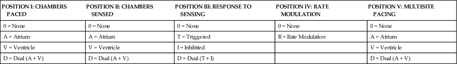
Modified from Bernstein AD, et al: The Revised NASPE/BPEG generic code for antibradycardia, adaptive-rate and multisite pacing, Pacing Clin Electrophysiol 25(2):260, 2002.
Synchronous Pacing Modes
Synchrony implies that the pacemaker only delivers a stimulus when the heart’s intrinsic pacemaker fails to function at a predetermined rate. The most physiological of the synchronous modes are those in which the normal sequential relationship between atrial and ventricular depolarization and contraction is maintained. Atrioventricular (AV) synchrony increases the volume in the ventricle before contraction and thus improves cardiac output. When atrial-to-ventricular conduction is impaired, as during heart block, AV synchrony can be maintained through a dual-chamber (both atrial and ventricular) pacing mode.
DDD Pacing
The most physiological of the AV pacing modes is the DDD mode. In DDD pacing, atrial and ventricular leads are used for both pacing and sensing (Table 13-2). In response to sensed activity, the pacemaker inhibits the pacing stimulus. Therefore a sensed P wave in the atrium will inhibit the atrial pacing stimulus, whereas a sensed R wave in the ventricle will inhibit the ventricular pacing stimulus. DDD pacing is also described as “universal pacing” or “physiological pacing” because it most closely resembles the heart’s intrinsic conduction system.
TABLE 13-2
EXAMPLES OF TEMPORARY PACING MODES
| PACING MODE | DESCRIPTION |
| Asynchronous | |
| AOO | Atrial pacing, no sensing |
| VOO | Ventricular pacing, no sensing |
| DOO | Atrial and ventricular pacing, no sensing |
| Synchronous | |
| AAI | Atrial pacing, atrial sensing, inhibited response to sensed P waves |
| VVI | Ventricular pacing, ventricular sensing, inhibited response to sensed QRS complexes |
| DVI | Atrial and ventricular pacing, ventricular sensing; both atrial and ventricular pacing are inhibited if a spontaneous ventricular depolarization is sensed |
| Universal | |
| DDD | Both chambers are paced and sensed; inhibited response of the pacing stimuli to sensed events in their respective chambers; triggered response to sensed atrial activity to allow for rate-responsive ventricular pacing |
VVI Pacing
The VVI mode is designed to pace the ventricle when the pacemaker does not sense an intrinsic (patient initiated) ventricular depolarization. Other names that are popularly used for this mode include “backup pacing” or “demand pacing” (see Table 13-2). VVI pacing is necessary in specific circumstances; the classic example is symptomatic bradycardia with atrial fibrillation. Because a fibrillating atrium is impossible to pace, one effective intervention is to use VVI pacing to maintain ventricular function.
Asynchronous Pacing Modes
Fixed-rate or asynchronous pacing modes ignore the patient’s intrinsic heartbeat. These modes are uncommon with the exception of two situations. Emergency DOO or VOO pacing may be used in asystole as a lifesaving measure. These modes are sometimes used in the operating room, where electromagnetic interference (EMI) from electrocautery and other electrical equipment can interfere with normal pacemaker function.
Pacemaker Settings
The controls on all external temporary pulse generators are similar. Their functions must be thoroughly understood so that pacing can be initiated quickly in an emergency situation and troubleshooting can be facilitated if problems with the pacemaker arise.
The rate control regulates the number of impulses that can be delivered to the heart per minute. The rate setting depends on the physiological needs of the patient, but it usually is maintained between 60 and 80 beats/min.
The output dial regulates the amount of electrical current, measured in milliamperes (mA), that is delivered to the heart to initiate depolarization. The point at which depolarization occurs, called threshold, is indicated by a myocardial response to the pacing stimulus (i.e., capture). Threshold can be determined by gradually decreasing the output setting until 1 : 1 capture is lost. The output setting is then slowly increased until 1 : 1 capture is reestablished; this threshold to pace is less than 1 mA with a properly positioned pacing electrode. The output is set two to three times higher than threshold, because thresholds tend to fluctuate over time. Box 13-1 details the procedure for measuring pacing thresholds. Separate output controls for atrium and ventricle are used with a dual-chamber pulse generator.
The sensitivity control regulates the ability of the pacemaker to detect the heart’s intrinsic electrical activity. Sensitivity is measured in millivolts (mV) and determines the size of the intracardiac signal that the generator will recognize. If the sensitivity is adjusted to its most sensitive setting—a setting of 0.5 to 1.0 mV—the pacemaker can respond even to low-amplitude electrical signals coming from the heart. Turning the sensitivity to its least sensitive setting (i.e., adjusting the dial to a setting of 20 mV or to the area labeled async) results in inability of the pacemaker to sense any intrinsic electrical activity and causes the pacemaker to function at a fixed rate. A sense indicator (often a light) on the pulse generator signals each time intrinsic cardiac electrical activity is sensed. A pulse generator may be designed to sense atrial activity, ventricular activity, or both. Box 13-2 describes the procedure for measuring sensitivity.
The AV interval control (available only on dual-chamber generators) regulates the time interval between the atrial and ventricular pacing stimuli. This interval is analogous to the PR interval that occurs in the intrinsic ECG. Proper adjustment of this interval to between 150 and 250 milliseconds (msec) preserves AV synchrony and permits maximal ventricular stroke volume and enhanced cardiac output.
Temporary DDD pacemakers have several other digital controls that are unique to this type of temporary pulse generator. The lower rate, or base rate, determines the rate at which the generator will pace when intrinsic activity falls below the set rate of the pacemaker. The upper rate determines the fastest ventricular rate the pacemaker will deliver in response to sensed atrial activity. This setting is needed to protect the patient’s heart from being paced in response to rapid atrial dysrhythmias. The pulse width, which can be adjusted from 0.05 to 2 msec, controls the length of time that the pacing stimulus is delivered to the heart. There is also an atrial refractory period, programmable from 150 to 500 msec, which regulates the length of time, after a sensed or paced ventricular event, during which the pacemaker cannot respond to another atrial stimulus. An emergency button is also available on most models to allow for rapid initiation of asynchronous (DOO) pacing during an emergency.
On all temporary pacemakers, an on/off switch is provided with a safety feature that prevents the accidental termination of pacing. Also a “lock” feature is used to prevent unintended changes to the prescribed settings.
Pacing Artifacts
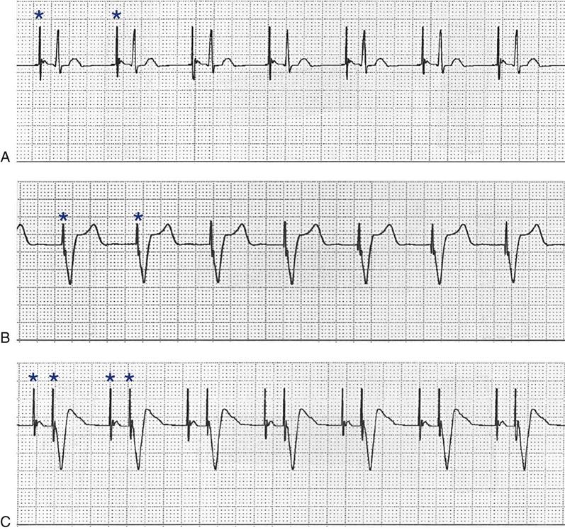
All patients with temporary pacemakers require continuous ECG monitoring. The pacing artifact is the spike that is seen on the ECG tracing as the pacing stimulus is delivered to the heart. A P wave is visible after the pacing artifact if the atrium is being paced (Figure 13-2, A). Similarly, a QRS complex follows a ventricular pacing artifact (see Figure 13-2, B). With dual-chamber pacing, a pacing artifact precedes both the P wave and the QRS complex (see Figure 13-2, C).
Pacemaker Malfunctions
Pacing Abnormalities
Most pacemaker malfunctions can be categorized as abnormalities of either pacing or sensing. Immediate and accurate recognition of these malfunctions is critically important in a pacemaker-dependent individual.
Failure to Pace
Failure of the pacemaker to deliver the pacing stimulus results in the disappearance of the pacing artifact on the bedside ECG monitor, even though the patient’s intrinsic rate is less than the set rate on the pacemaker (Figure 13-3). This can occur either intermittently or continuously and can be attributed to failure of the pulse generator or its battery, a loose connection between the various components of the pacemaker system, broken lead wires, or stimulus inhibition as a result of EMI. Tightening connections, replacing the batteries or the pulse generator itself, or removing the source of EMI may restore pacemaker function.
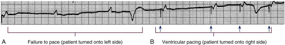
A, Patient with a transvenous pacemaker is turned onto the left side. Immediately, there is a failure to pace (i.e., loss of pacer artifacts on the electrocardiogram). The patient’s heart rate is extremely low without pacemaker support. B, The nurse turns the patient onto the right side, the transvenous electrode floats into contact with the right ventricular wall, and pacing is resumed. (From Kesten KS, Norton CK: Pacemakers: patient care, troubleshooting, rhythm analysis, Baltimore, 1985, Resource Applications.)
Failure to Capture
If the pacing stimulus fires but fails to initiate a myocardial depolarization, a pacing artifact will be present but will not be followed by the expected P wave or QRS complex, depending on the chamber being paced (Figure 13-4). This “loss of capture” most often can be attributed either to displacement of the pacing electrode or to an increase in the threshold (electrical stimulus necessary to elicit a myocardial depolarization) as a result of medications, metabolic disorders, electrolyte imbalances, or fibrosis or myocardial ischemia at the site of electrode placement. In many cases, increasing the output (mA) may elicit capture. For transvenous leads, repositioning the patient to the left side may improve lead contact and restore capture.1
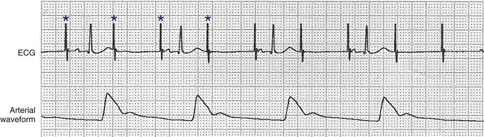
Atrial pacing and capture occur after pacer artifacts (spikes) 1, 3, 5, and 7. The remaining pacer artifacts fail to capture the tissue, resulting in loss of the P wave, no conduction to the ventricles, and no arterial waveform. Each asterisk represents a pacemaker impulse.
Pacing can occur at inappropriate rates. For example, impending battery failure in a permanent pacemaker can result in a gradual decrease in the paced rate, also referred to as rate drift. Inappropriate stimuli from a pacemaker may result in a pacemaker-mediated tachycardia. This usually is caused by sensing of inappropriate signals in a dual-chamber pacemaker that is in a trigger mode, such as DDD. Placing a magnet over the generator to transiently suspend sensing can terminate the tachycardia.1
Sensing Abnormalities
Sensing abnormalities include both undersensing and oversensing.
Undersensing
Undersensing is the inability of the pacemaker to sense spontaneous myocardial depolarizations. Undersensing results in competition between paced complexes and the heart’s intrinsic rhythm. This malfunction is manifested on the ECG by pacing artifacts that occur after or are unrelated to spontaneous complexes (Figure 13-5). Undersensing can result in the delivery of pacing stimuli into a relative refractory period of the cardiac depolarization cycle. A ventricular pacing stimulus delivered into the downslope of the T wave (R-on-T phenomenon) is a real danger with this type of pacer aberration, because it may precipitate a lethal dysrhythmia. The nurse must act quickly to determine the cause and initiate appropriate interventions. Frequently the cause can be attributed to inadequate wave amplitude (height of the P or R wave). If this is the case, the situation can be promptly remedied by increasing the sensitivity by moving the sensitivity dial toward its lowest setting. Other possible causes include inappropriate (asynchronous) mode selection, lead displacement or fracture, loose cable connections, and pulse generator failure.
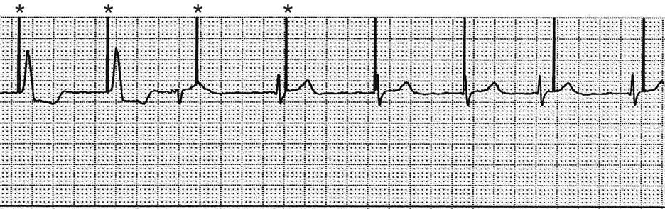
After the first two paced beats, a series of intrinsic beats occur; the pacemaker unit fails to sense these intrinsic QRS complexes. These pacer artifacts do not capture the ventricle because they occur during the refractory period of the cardiac cycle. Each asterisk represents a pacemaker impulse.
Oversensing
Oversensing occurs as a result of inappropriate sensing of extraneous electrical signals that leads to unnecessary triggering or inhibition of stimulus output, depending on the pacer mode. The source of these electrical signals can range from tall peaked T waves to EMI in the critical care environment. Because most temporary pulse generators are programmed in demand modes, oversensing results in unexplained pauses in the ECG tracing as the extraneous signals are sensed and inhibit pacing. Often, moving the sensitivity dial toward 20 mV (less sensitive) stops the pauses. With permanent pacemakers, a magnet may be placed over the generator to restore pacing in an asynchronous mode until appropriate changes in the generator settings can be programmed.
Medical Management
The physician determines the pacing route based on the patient’s clinical situation. Transcutaneous pacing typically is used in emergent situations until a transvenous lead can be secured. If the patient is undergoing heart surgery, epicardial leads may be electively placed at the end of the operation. The physician places the transvenous or epicardial pacing lead or leads, repositioning them as needed to obtain adequate pacing and sensing thresholds. Decisions regarding lead placement may later limit the pacing modes available to the clinician. For example, to perform dual-chamber pacing, both atrial and ventricular leads must be placed. In an emergency, however, interventions are focused on establishing ventricular pacing, and atrial lead placement may not be feasible. After lead placement, the initial settings for output and sensitivity are determined, the pacing rate and mode are selected, and the patient’s response to pacing is evaluated.
Nursing Management
Nursing priorities in the care of a patient with a temporary pacemaker can be combined into four primary areas: (1) preventing pacemaker malfunction, (2) protecting against microshock, (3) monitoring for complications, and (4) providing patient education.
Preventing Pacemaker Malfunction
Continuous ECG monitoring is essential to facilitate prompt recognition of and appropriate intervention for pacemaker malfunction. Proper care of the pacing system can prevent pacing abnormalities.
The temporary pacing lead and bridging cable must be properly secured to the body with tape to prevent accidental displacement of the electrode, which can result in failure to pace or sense. The external pulse generator can be secured to the patient’s waist with a strap or placed in a telemetry bag for the mobile patient. If the patient is on a regimen of bed rest, the pulse generator can be suspended with twill tape from an IV pole mounted overhead on the ceiling. This prevents tension on the lead while the patient is moved (given adequate length of bridging cable) and alleviates the possibility of accidental disconnection or dropping of the pulse generator.
The nurse inspects for loose connections between the leads and pulse generator on a regular basis.5 Replacement batteries and pulse generators must always be available on the unit. Although the battery has an anticipated life span of 1 month, it probably is sound practice to change the battery if the pacemaker has been operating continually for several days. Newer generators provide a low-battery signal 24 hours before complete loss of battery function occurs to prevent inadvertent interruptions in pacing. The pulse generator must always be labeled with the date on which the battery was replaced.
Protecting against Microshock
It is important to be aware of all sources of EMI within the critical care environment that may interfere with the pacemaker’s function. Sources of EMI in the clinical area include electrocautery, defibrillation current, radiation therapy, magnetic resonance imaging devices, and transcutaneous electrical nerve stimulation (TENS) units.3 In most cases, if EMI is suspected of precipitating pacemaker malfunction, conversion to the asynchronous mode (fixed rate) can maintain pacing until the cause of the EMI is removed.
Because the pacing electrode provides a direct, low-resistance path to the heart, the nurse takes special care while handling the external components of the pacing system to avoid conducting stray electrical current from other equipment. Even a small amount of stray current transmitted through the pacing lead could precipitate a lethal dysrhythmia. The possibility of microshock can be minimized by wearing rubber gloves when handling the pacing wires and by proper insulation of terminal pins of pacing wires when they are not in use. The latter precaution can be accomplished by the use of caps provided by the manufacturer or by improvising with a plastic syringe or section of disposable rubber glove. The wires are taped securely to the patient’s chest to prevent accidental electrode displacement. Additional safety measures include using a nonelectric or a properly grounded electric bed, keeping all electrical equipment away from the bed, and permitting the use of only rechargeable electric razors.
Monitoring for Complications
Infection at the lead insertion site is a rare but serious complication associated with temporary pacemakers. The site is carefully inspected for purulent drainage, erythema, and edema, and the patient is observed for signs of systemic infection. Site care is performed according to the institution’s policies and procedures. Although most infections remain localized, endocarditis can occur in patients with endocardial pacing leads.
During transvenous pacing insertion, a balloon at the tip of the catheter is inflated with air to facilitate transvenous insertion. Once the tip of the pacing catheter is correctly positioned within the heart chamber, the balloon is deflated. It is important that the external balloon port is labeled to avoid inadvertent access.5 A rare complication associated with transvenous pacing is myocardial perforation, which can result in rhythmic hiccoughs or cardiac tamponade.
Providing Patient Education
Patient teaching for the person with a temporary pacemaker emphasizes the prevention of complications. The patient is instructed not to handle any exposed portion of the lead wire and to notify the nurse if the dressing over the insertion site becomes soiled, wet, or dislodged. When epicardial pacemaker wires are removed following cardiac surgery, explain that a pulling sensation may be experienced.6 The patient is advised not to use any electrical devices brought in from home that could interfere with pacemaker functioning.
Patients with temporary transvenous pacemakers need to be taught to restrict movement of the affected extremity to prevent lead displacement.
Permanent Pacemakers
More than 195,000 permanent pacemakers are implanted annually in the United States, and critical care nurses are likely to encounter these devices in their clinical practice.7 These pacemakers were originally designed to provide an adequate ventricular rate in patients with symptomatic bradycardia. Today, the goal of pacemaker therapy is to simulate, as much as possible, normal physiological cardiac depolarization and conduction. Sophisticated generators permit rate-responsive pacing, affecting responses to sensed atrial activity (DDD) or to a variety of physiological sensors (body motion, QT interval, minute ventilation). For patients who do not have a functional sinus node that can increase their heart rate, rate-responsive pacemakers have been shown to improve exercise capacity and quality of life.8 Table 13-3 describes the types of rate-responsive pacing modes in clinical use.
TABLE 13-3
PERMANENT PACEMAKER RATE-RESPONSE PACING MODES
| PULSE GENERATOR | DESCRIPTION |
| AAIR | AAI features plus rate-responsive pacing; used for patients with a symptomatic bradycardia who have a paceable atrium and intact AV conduction |
| VVIR | VVI features plus rate-responsive pacing; used for patients with an atrium that is unpaceable as a result of chronic atrial fibrillation or other atrial dysrhythmia |
| DDDR | DDD features plus rate-responsive pacing; used for patients with symptomatic bradycardia in which the atrium is paceable but AV conduction is, or may become, unreliable |
The concept of physiological pacing continues to evolve, because studies have indicated that pacing initiated from the RV apex—even in a dual-chamber mode—may promote heart failure in patients with permanent pacemakers.1 This has prompted further research to identify alternative sites for pacing and modes that can maximize intrinsic AV conduction and minimize ventricular pacing.8
Technological advances in the computer industry have had a major impact on today’s permanent pacemakers. Microprocessors have allowed for the development of increasingly smaller generators despite the incorporation of more complex features. Today’s pacemaker generators are smaller, more energy-efficient, and more reliable than previous models. A new trend in permanent pacemakers is to use these devices as nonpharmacological therapy in treatment of heart failure.
Cardiac Resynchronization Therapy
About one third of patients with severe heart failure have ventricular conduction delays (prolonged QRS duration or bundle branch block). These conduction delays have been shown to create a lack of synchrony between the contractions of the LV and RV. The hemodynamic consequences of this dyssynchrony include impaired ventricular filling with decreased ejection fraction, cardiac output, and mean arterial pressure.9 Cardiac resynchronization therapy (CRT) uses atrial pacing plus stimulation of both the LV and RV (biventricular pacing), in an attempt to optimize atrial and ventricular mechanical activity. The CRT device uses three pacing leads, one each in the right atrium and the RV and a specially designed transvenous lead that is inserted through the coronary sinus to pace the LV.9 Because many patients with heart failure are also at risk for sudden cardiac death, biventricular pacing is available on some implantable cardioverter defibrillators (ICDs). A number of clinical trials have shown symptomatic and structural cardiac improvement with this new therapy.10
Atrial Arrhythmia Suppression
There is a growing incidence of atrial fibrillation, and atrial pacing has been proposed as a possible preventative therapy for this dysrhythmia in selected patients. Atrial pacing in patients with bradycardia has been shown to lower the recurrence of atrial fibrillation, especially compared with ventricular pacing.11 Most pacemakers can be programmed to mode switch to a non-P wave tracking mode if rapid atrial rates are sensed.1 Strategies for patients with paroxysmal atrial fibrillation, which include pacing both atriums (bi-atrial pacing) and transiently pacing the atrium at a rate higher than the patient’s intrinsic sinus rate, require further study.12
Medical Management
Permanent pacemakers may be implanted with the patient under local anesthesia in the operating room or in the cardiac catheterization laboratory. Transvenous leads usually are inserted through the cephalic or subclavian vein and positioned in the right atrium or RV, or both, with fluoroscopic guidance. Satisfactory lead placement is determined by testing the stimulation and sensitivity thresholds with a pacing system analyzer. The leads are then attached to the generator, which is inserted into a surgically created pocket in the subcutaneous tissue below the clavicle.
Nursing Management
Nursing management for patients after permanent pacemaker implantation includes monitoring for complications related to insertion and for pacemaker malfunction. Postoperative complications are rare but include cardiac perforation and tamponade, pneumothorax, hematoma, lead displacement, and infection.13,14
Identification of permanent pacemaker malfunction is the same as that described previously for temporary pacemakers. To evaluate pacemaker function, the nurse must know at least the pacemaker’s programmed mode of pacing and the lower rate setting. With permanent pacemakers, settings are adjusted noninvasively through a specialized programmer that uses pulsed magnetic fields or an RF signal. If a pacemaker problem is suspected, ECG strips are obtained, and the physician is notified so that the pacemaker settings can be reprogrammed as needed. If the patient experiences symptoms of decreased cardiac output, he or she may require support with temporary transcutaneous pacing until the problem is corrected.
Critical care nurses also may be involved in monitoring patients with permanent pacemakers after discharge. Some units are equipped with transtelephonic monitoring equipment that allows patients to transmit information over the telephone from a monitoring device in their home. Transmission of the patient’s ECG can provide information to confirm proper pacemaker function (capture and sensing) and to determine battery status (rate). Newer technology that uses an Internet-based remote monitoring system for pacemaker follow-up may soon replace standard transtelephonic ECG evaluation.15
The foregoing discussion provides an introduction to the basic concepts of pacemaker therapy. However, the nurse who cares for patients with permanent or temporary pacemakers must be familiar with even the most sophisticated modes of pacemaker function. Only by keeping pace with current technology can the nurse accurately interpret pacer function and thereby safely and effectively care for patients with pacemakers.
Implantable Cardioverter Defibrillators
An implantable cardioverter defibrillator (ICD) is an electronic device that is used in the treatment of tachydysrhythmias. The ICD is capable of identifying and terminating life-threatening ventricular dysrhythmias; 114,000 are implanted annually in the U.S.7 Initially, an ICD was recommended only for patients who had survived an episode of cardiac arrest caused by ventricular fibrillation (VF) or ventricular tachycardia (VT). Later, a number of clinical trials compared ICD therapy for such secondary prevention of sudden cardiac death with antidysrhythmic drug therapy and found improved survival with the ICD.1 As a result, ICD use was expanded to include primary prevention of sudden cardiac death in patients with coronary artery disease (CAD), previous MI, or LV dysfunction in whom VT or VF was inducible during EPS. Trials have shown improved survival with ICD implantation in high-risk patients (i.e., those with previous MI and an ejection fraction <35%) even without evidence of VT or VF on an EPS.10 These results have further increased the number of patients who receive an ICD.
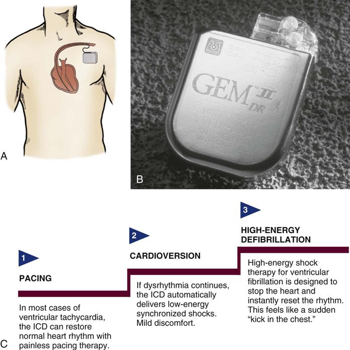
The ICD System
The ICD system contains (1) sensing electrodes to recognize the dysrhythmia and (2) defibrillation electrodes or patches that are in contact with the heart and can deliver a shock. These electrodes are connected to a generator that is surgically placed in the subcutaneous tissue of the pectoral region in the upper chest (Figure 13-6). The early-model generators could defibrillate or cardiovert only lethal dysrhythmias. The current generation of devices delivers a tiered therapy, with options for programmable antitachycardia pacing, bradycardia backup pacing, low-energy cardioversion, and high-energy defibrillation. With tiered therapy, antitachycardia pacing is used as the first line of treatment in some cases of VT. If the VT can be pace-terminated successfully, the patient will not receive a shock from the generator and may not even realize that the ICD terminated the dysrhythmia. If programmed bursts of pacing do not terminate the VT, the ICD will cardiovert the rhythm. If the dysrhythmia deteriorates into VF, the ICD is programmed to defibrillate at a higher energy. If the dysrhythmia terminates spontaneously, the device will not discharge. Occasionally, the electrical rhythm may deteriorate to asystole or a slow idioventricular rhythm; in such cases, the bradycardia backup pacing function is activated.
ICDs are dual-chamber devices with leads in both atria and ventricles. The atrial leads allows for dual-chamber pacing to optimize hemodynamic performance and atrial sensing to more accurately discriminate between atrial and ventricular tachycardias and to decrease the incidence of inappropriate shocks. Implantable defibrillators with atrial capabilities may also be used to deliver therapies such as cardioversion or antitachycardia pacing to patients with atrial tachydysrhythmias, but their use may be limited because of the painful nature of the shocks.12 ICDs may also incorporate triple-lead systems (leads in one atrium and both ventricles) to allow for CRT and defibrillation in one device. Other developments in ICD technology include improved diagnostic and telemetry functions, such as the ability to provide real-time electrograms obtained from the ICD electrodes or the ability to perform remote device interrogation by telephone or Internet.16
ICD Insertion
The ICD has progressed in both programmable functions and insertion design. Transvenous electrode leads are inserted into the subclavian vein and advanced into the right side of the heart, where contact with the endocardium is achieved. The endocardial leads are used for sensing, pacing, cardioversion, and defibrillation, and are connected to the generator by tunneling through the subcutaneous tissue. Technical advances and the development of smaller ICDs have made it feasible to implant these devices in the pectoral position, similar to permanent pacemakers.
Medical Management
Medical management in the ICD patient begins before implantation with a thorough evaluation of the patient’s dysrhythmia and underlying cardiac function. Patients at risk for sudden cardiac death (SCD) undergo an electrophysiology study to determine the origin of the dysrhythmia and the effect of antidysrhythmic agents in suppressing or altering the rate of the dysrhythmia. Further assessment of cardiac status is made to determine whether additional interventions (e.g., cardiac surgery, angioplasty or stent) are indicated to improve cardiac function and decrease SCD risk.
ICD Programming
An electrophysiologist performs the initial programming of the device at the time of implantation. During implantation, defibrillation threshold measurements are obtained. This involves inducing the dysrhythmia and then evaluating the device’s ability to terminate it. After it has been determined that the ICD functions appropriately, further follow-up is conducted on an outpatient basis to monitor the number of discharges and the battery life of the device.
Nursing Management
It is important to know the type of ICD implanted, how the device functions, and whether it is activated (i.e., on). If the patient experiences a shockable rhythm, the nurse should be prepared to defibrillate in the rare event that the device fails. During external defibrillation, the paddles or patches should not be placed directly over the ICD generator. Standard paddle placement may need to be altered in patients with ICDs to achieve successful defibrillation.2 Most patients continue to take antidysrhythmic medications to decrease the number of shocks required and to slow the rate of the tachycardia. Complications associated with the permanent ICD include infection from the implanted system,14 broken leads, and sensing of supraventricular tachydysrhythmias resulting in unneeded discharges.
Providing Patient Education
To facilitate a positive psychological adjustment to the ICD, patient education about the device is vital.17,18 Preoperative teaching for the ICD patient includes information about how the device works and what to expect during the implantation procedure. After implantation, education is focused on aspects of living with an ICD. Patients need information pertaining to scheduled device follow-up and instructions about what to do if they experience a shock. Many institutions have successfully used family support groups for this patient population.
Fibrinolytic Therapy
Fibrinolytic therapy is an important clinical intervention for the patient experiencing acute ST-elevation myocardial infarction (STEMI). Before the introduction of fibrinolytic agents, medical management of acute MI was focused on decreasing myocardial oxygen demands to minimize myocardial necrosis and preserve ventricular function. Today, efforts to limit the size of the infarction are directed toward timely reperfusion of the jeopardized myocardium through restoration of blood flow in the culprit vessel (the open artery theory). Two options are available for opening the artery—fibrinolytics and mechanical intervention. Although mechanical catheter-based intervention has been proven to yield better outcomes when performed in a timely fashion, only 25% of U.S. hospitals are estimated to have this capability.19 For this reason, fibrinolytic therapy continues to play a major role in the treatment of acute MI.
The use of fibrinolytic therapy is predicated on the theory that the significant event in acute coronary syndromes (e.g., unstable angina, acute MI) is the rupture of an atherosclerotic plaque with thrombus formation (Figure 13-7). The thrombus, which is composed of aggregated platelets bound together with fibrin strands, occludes the coronary artery, depriving the myocardium of oxygen previously supplied by that artery. The administration of a fibrinolytic agent results in lysis of the acute thrombus, resulting in recanalization, or opening, of the obstructed coronary artery and restoration of blood flow to the affected tissue. After perfusion is restored, adjunctive measures are taken to prevent further clot formation and repeat occlusion.
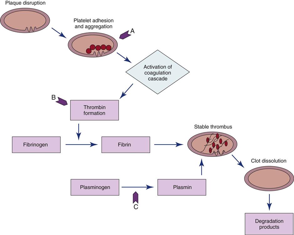
A, Site of action of antiplatelet agents such as aspirin and glycoprotein IIb/IIIa inhibitors. B, Heparin bonds with antithrombin III and thrombin to create an inactive complex. C, Fibrinolytic agents convert plasminogen to plasmin, an enzyme responsible for degradation of fibrin clots.
Eligibility Criteria
Inclusion Criteria
Certain criteria have been developed, based on research findings, to determine the patient population that would most likely benefit from the administration of fibrinolytic therapy. Patients with recent onset of chest pain (<12 hours’ duration) and persistent ST elevation (>0.1 mV in two or more contiguous leads) are considered candidates for fibrinolytic therapy.20 Patients who present with bundle branch blocks that may obscure ST-segment analysis and a history suggesting an acute MI are also considered candidates for therapy. The goal of therapy is to administer fibrinolytic therapy within 30 minutes after presentation at the hospital, described as “door-to-needle” time. Time is crucial because early reperfusion yields the greatest benefit.21
Exclusion criteria are usually based on the increased risk of bleeding incurred from the use of fibrinolytics. Patients who have stable clots that might be disrupted by fibrinolytic therapy (recent surgery, trauma, or stroke) usually are not considered candidates for fibrinolytic therapy. Other selection criteria for the use of fibrinolytic therapy are presented in Box 13-3.
Exclusion Criteria
Currently, fibrinolytic therapy is not indicated for patients with unstable angina or non-ST-elevation myocardial infarction (NSTEMIs). It is believed that these conditions result from plaque rupture with the formation of an only partially occlusive thrombus. Fibrinolysis breaks up the clot and releases thrombin, and this can paradoxically increase the material necessary for further thrombosis.22 Instead, these patients are treated with antiplatelet agents (e.g., aspirin, clopidogrel, glycoprotein IIb/IIIa inhibitors) and antithrombin drugs (e.g., heparin).
Fibrinolytic Agents
Four fibrinolytic agents are currently available for intravenous treatment of acute STEMI. All of these agents stimulate lysis of the clot by converting inactive plasminogen to plasmin, an enzyme responsible for degradation of fibrin. Streptokinase (SK) and urokinase were the first generation of fibrinolytic agents and had their primary effect on circulating plasminogen. Urokinase availability has been limited because of manufacturing problems. Newer fibrinolytic agents (e.g., alteplase, reteplase, tenecteplase) have a greater effect on clot plasminogen than on circulating plasminogen and are described as clot selective. A comparison of currently approved fibrinolytic agents is provided in Table 13-4.
TABLE 13-4
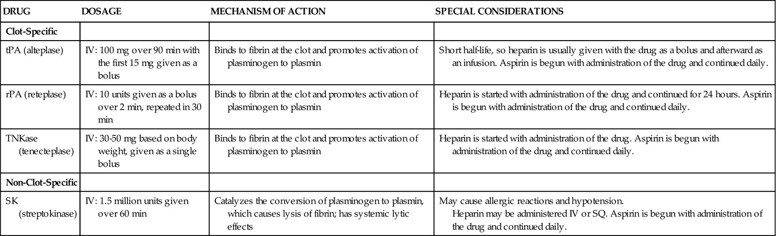
PHARMACOLOGICAL MANAGEMENT: FIBRINOLYTIC AGENTS FOR USE IN ACUTE MYOCARDIAL INFARCTION
| DRUG | DOSAGE | MECHANISM OF ACTION | SPECIAL CONSIDERATIONS |
| Clot-Specific | |||
| tPA (alteplase) | IV: 100 mg over 90 min with the first 15 mg given as a bolus | Binds to fibrin at the clot and promotes activation of plasminogen to plasmin | Short half-life, so heparin is usually given with the drug as a bolus and afterward as an infusion. Aspirin is begun with administration of the drug and continued daily. |
| rPA (reteplase) | IV: 10 units given as a bolus over 2 min, repeated in 30 min | Binds to fibrin at the clot and promotes activation of plasminogen to plasmin | Heparin is started with administration of the drug and continued for 24 hours. Aspirin is begun with administration of the drug and continued daily. |
| TNKase (tenecteplase) | IV: 30-50 mg based on body weight, given as a single bolus | Binds to fibrin at the clot and promotes activation of plasminogen to plasmin | Heparin is started with administration of the drug. Aspirin is begun with administration of the drug and continued daily. |
| Non-Clot-Specific | |||
| SK (streptokinase) | IV: 1.5 million units given over 60 min | Catalyzes the conversion of plasminogen to plasmin, which causes lysis of fibrin; has systemic lytic effects | May cause allergic reactions and hypotension. Heparin may be administered IV or SQ. Aspirin is begun with administration of the drug and continued daily. |
Because patients with an area of plaque disruption are still at risk for clot formation and reocclusion, fibrinolytic therapy is used in conjunction with anticoagulants and antiplatelet agents. Current guidelines recommend that heparin be administered for a minimum of 48 hours after fibrinolytic therapy. Low-molecular-weight heparin (LMWH) is considered an acceptable alternative in patients younger than 75 years who have adequate kidney function. Antiplatelet therapy with clopidogrel is recommended for 14 days, and aspirin should be continued indefinitely20 (Table 13-5).
TABLE 13-5
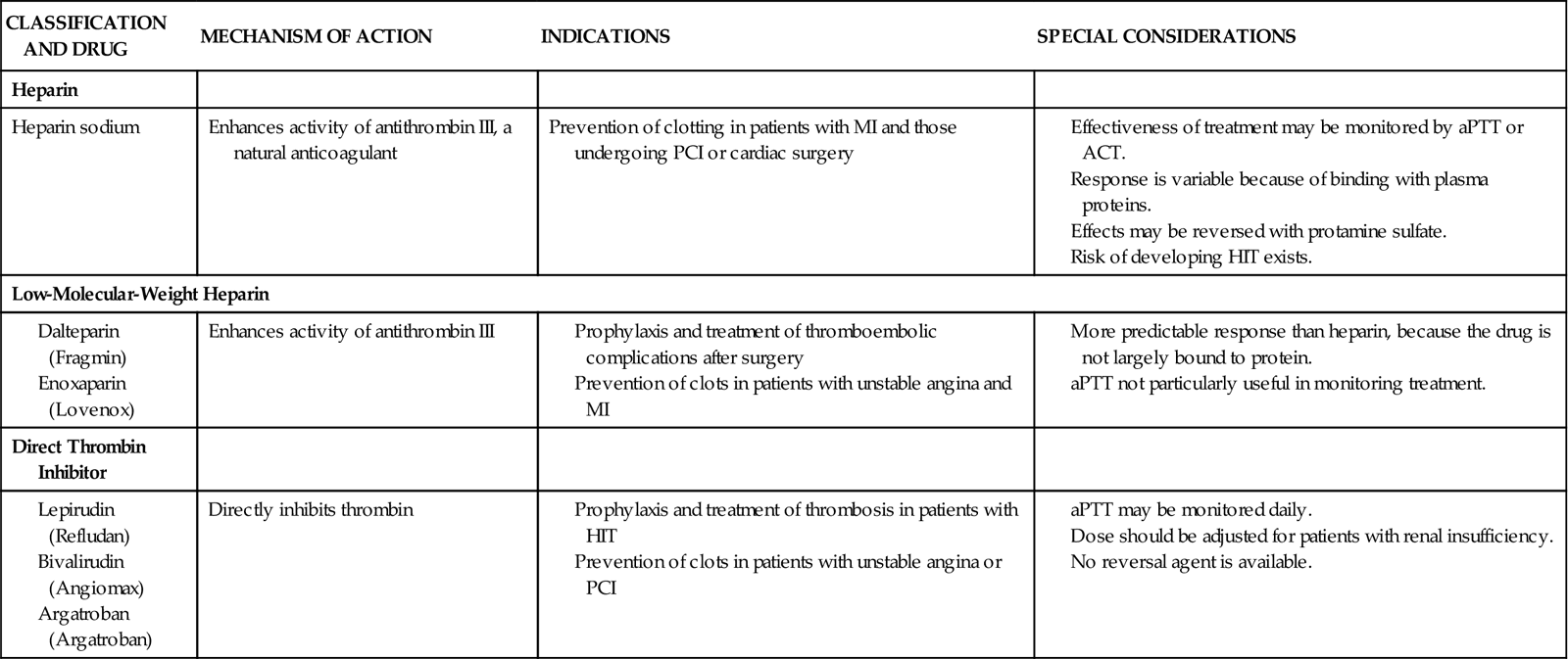
PHARMACOLOGICAL MANAGEMENT: ANTICOAGULANTS
Outcomes of Fibrinolytic Therapy
The benefit of fibrinolytic therapy correlates with the degree of restoration of normal blood flow in the infarct-related artery. Coronary artery patency is defined by angiographic perfusion grades developed by the Thrombolysis in Myocardial Infarction (TIMI) study group in 1985 (Box 13-4).23 Achievement of TIMI grade 3 flow is associated with the best long-term survival. Studies also indicate that rapid restoration of normal blood flow, within 90 minutes after treatment, results in improved LV function and reduced mortality. The three fibrin-specific fibrinolytics have been shown to achieve TIMI 3 flow in 54% to 63% of patients at 90 minutes.24
The area of fibrinolytic therapy continues to evolve, and drug dose ranges and regimens are subject to change when research findings are updated. Whereas fibrinolytic agents target the fibrin portion of the clot, other treatment strategies are focusing on the platelet portion of the clot (see Figure 13-7). Clinical trials evaluating the combination of glycoprotein IIb/IIIa receptor antagonists with fibrinolytic agents (at half-dose) found outcomes equivalent to those of fibrinolytics alone, but with an increased risk for bleeding.25 There was also speculation that a planned strategy for administering fibrinolytics or glycoprotein IIb/IIIa receptor antagonists, or both, to patients who must be transported to another facility for percutaneous intervention would improve outcomes. Although promising in theory, this facilitated approach to revascularization has not been shown to be beneficial and may increase the risk for bleeding complications in some patients.26
Evidence of Reperfusion
In the cardiac catheterization laboratory, the blood flow of a vessel that has been occluded by a thrombus and then opened by fibrinolytic therapy can be observed directly under fluoroscopy. The adequacy of the flow of blood through the coronary artery is described using the standardized thrombolysis in myocardial infarction (TIMI) scale (Box 13-4).
Nursing Management
Nursing priorities for the patient receiving fibrinolytic therapy are directed toward (1) identifying candidates for reperfusion therapy, (2) observing for signs of reperfusion, (3) monitoring for signs of bleeding, and (4) providing patient education.
Identifying Candidates for Reperfusion Therapy
Nursing management of the patient undergoing fibrinolytic therapy begins with identifying potential candidates. In many institutions, checklists are used to facilitate the rapid identification of patients who are candidates for fibrinolytics. The nurse prepares the patient for fibrinolytic therapy by starting intravenous lines and obtaining baseline laboratory values and vital signs.
Observing for Signs of Reperfusion
Reperfusion of the ischemic myocardium may be observed noninvasively by several means, as follows:
Monitoring for Signs of Bleeding
The most common complication related to thrombolysis is bleeding, from the fibrinolytic therapy itself and also because patients routinely receive anticoagulation therapy for several days to minimize the possibility of rethrombosis. The nurse must continually monitor for clinical manifestations of bleeding. Mild gingival bleeding and oozing around venipuncture sites is common and not a cause of concern. Should serious bleeding occur, such as intracranial or internal bleeding, all fibrinolytic and heparin therapies are discontinued and volume expanders or coagulation factors, or both, are administered.
In addition to accurate assessment of the patient for evidence of bleeding, nursing management includes preventive measures to minimize the potential for bleeding. For example, patient handling is limited, injections are avoided if at all possible, and additional pressure is provided to ensure hemostasis at venipuncture and arterial puncture sites. Intravenous lines are placed before lytic therapy is administered. A heparin lock may be used for obtaining laboratory specimens during treatment.
Providing Patient Education
Education for the patient receiving fibrinolytic therapy includes information regarding the actions of fibrinolytic agents, with emphasis on precautions to minimize bleeding. For example, the patient is cautioned against vigorous tooth brushing and told to refrain from using straight-edge razors. Information is provided regarding ongoing risk-factor management in the prevention of atherosclerotic CAD.
Catheter Interventions for Coronary Artery Disease
During the past three decades, the use of catheter procedures to open coronary arteries blocked or narrowed by CAD has expanded dramatically. These procedures are grouped by the term percutaneous coronary intervention (PCI). Today, PCI includes percutaneous transluminal coronary angioplasty (PTCA), atherectomy, and stent implantation. Advances in device technology, along with more effective anticoagulant and antiplatelet regimens, have reduced complication rates and improved procedural outcomes.28
Indications for Catheter-Based Interventions
Indications for catheter-based interventions have been considerably broadened since the initial application of balloon angioplasty. Whereas only patients with single-vessel CAD were once considered for PTCA, patients with multivessel disease, even those who have previously undergone saphenous vein grafting, internal mammary artery (IMA) grafting, or fibrinolytic therapy for acute MI, may now be candidates for catheter intervention. Previously seen as a rescue procedure to reduce a severe stenosis that persisted after fibrinolytic therapy, PCI is now preferred as the initial method of treatment for acute MI (primary PCI) when this therapy is available in the hospital.29 See “Coronary Artery Disease” in Chapter 12.
Surgical Backup
Initially, most institutions required that patients preparing to undergo angioplasty be candidates for coronary artery bypass graft (CABG) surgery. Complications such as intimal dissection with abrupt closure of the vessel could arise during the procedure, requiring the patient to undergo emergency CABG. Today, most dissections are effectively treated with stent placement, with less than 1% of patients requiring emergency bypass surgery. As a result, most institutions use an informal surgical backup plan, such as the first available operating room. Nevertheless, the availability of cardiac surgical services on site is still recommended. The one exception is in institutions that offer PCI only for treatment of acute STEMI. In this setting, an organized plan for emergent transfer to a surgical center may be used in lieu of on-site surgical access.30
Angioplasty
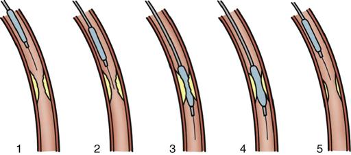
PTCA involves the use of a balloon-tipped catheter that, when advanced through an atherosclerotic lesion (atheroma), can be inflated intermittently for the purpose of dilating the stenotic area and improving blood flow through it (Figure 13-8). The high inflation pressure of the balloon stretches the vessel wall, fractures the plaque, and enlarges the vessel lumen. After balloon deflation, the vessel exhibits some degree of elastic recoil, resulting in a residual stenosis of approximately 30%.31 A successful angioplasty procedure is one in which the stenosis is reduced to less than 50% of the vessel lumen diameter.30
Restenosis occurred in more than one third of patients who underwent PTCA as a solo procedure. Restenosis within the first 6 months was diagnosed when patients experienced a recurrence of anginal symptoms.32 Studies showed that restenosis was influenced by the final lumen diameter after PTCA, the severity of elastic recoil of the vessel walls in response to the balloon inflation, and the amount of intimal hyperplasia that occurred as the vessel healed over the treated area. Patient characteristics such as a history of diabetes or unstable angina were also found to increase the risk of restenosis.33 Today, PTCA is rarely used alone as an intervention, except to treat lesions in very small coronary arteries.31 Nevertheless, balloon angioplasty remains an essential technique in PCI for dilating vessels and for deploying intracoronary stents.
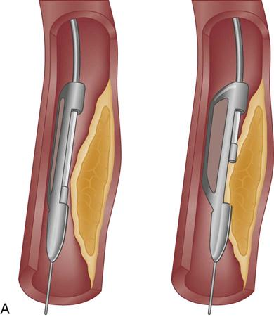
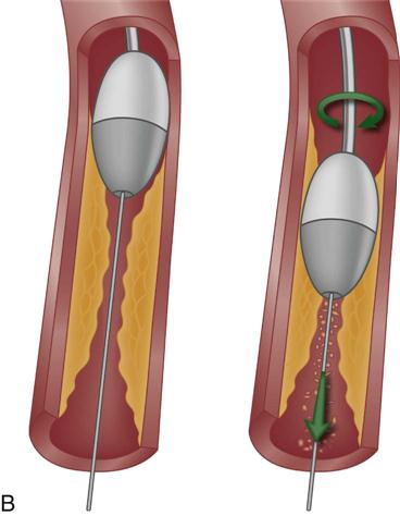
Atherectomy
Atherectomy is the excision and removal of the atherosclerotic plaque by cutting, shaving, or grinding. Specialized coronary catheters are used. Initially, atherectomy devices were used alone in an attempt to avoid the trauma to the vessel that was known to occur with balloon angioplasty and to more efficiently remove the atherosclerotic plaque, thereby decreasing the rate of restenosis. Later, as restenosis was also found to occur with these devices, balloon angioplasty was added as an adjunctive therapy to optimize the diameter of the vessel lumen and offset the intimal hyperplasia that occurred as a result of the procedure. Despite significant improvements in initial procedural success, atherectomy failed to significantly reduce the rate of restenosis.34 In the current era of stenting, atherectomy devices are used in less than 5% of procedures.31
Two atherectomy devices are used in PCI: directional coronary atherectomy (DCA) (Figure 13-9, A) and rotational ablation (Rotablator) (Figure 13-9, B). A randomized clinical trial showed no clinical benefit for the use of DCA in combination with stent, compared with stenting alone.35 As a result, DCA is currently used only for noncalcified lesions that involve a bifurcation of a major side branch or in the ostium of the left anterior descending (LAD) artery.28 Rotational atherectomy is used for chronic total occlusion and for calcified bifurcation lesions.28
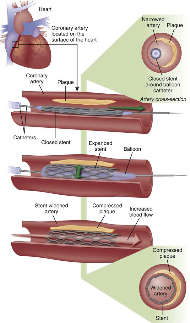
Coronary Stents
A major development in the field of interventional cardiology has been the coronary stent prosthesis. A stent is a metal structure that is introduced into the coronary artery over a guidewire and expanded into the vessel wall at the site of the lesion (Figure 13-10). Bare metal stents were first used to treat acute or threatened vessel closure after failed PTCA.32 The stent acted as a scaffold to tack dissection flaps against the vessel wall and provided mechanical support to minimize elastic recoil. Multiple stents may be implanted sequentially within a vessel to fully cover the area of the lesion. Stents are currently the predominant form of PCI and are used in more than 90% of all interventional procedures.7 Numerous stent models are available. They are composed of various types of metal (stainless steel, titanium, cobalt chromium) and come in a variety of configurations (e.g., mesh, coil). Most stents are balloon expandable (see Figure 13-10).
Stent Thrombosis
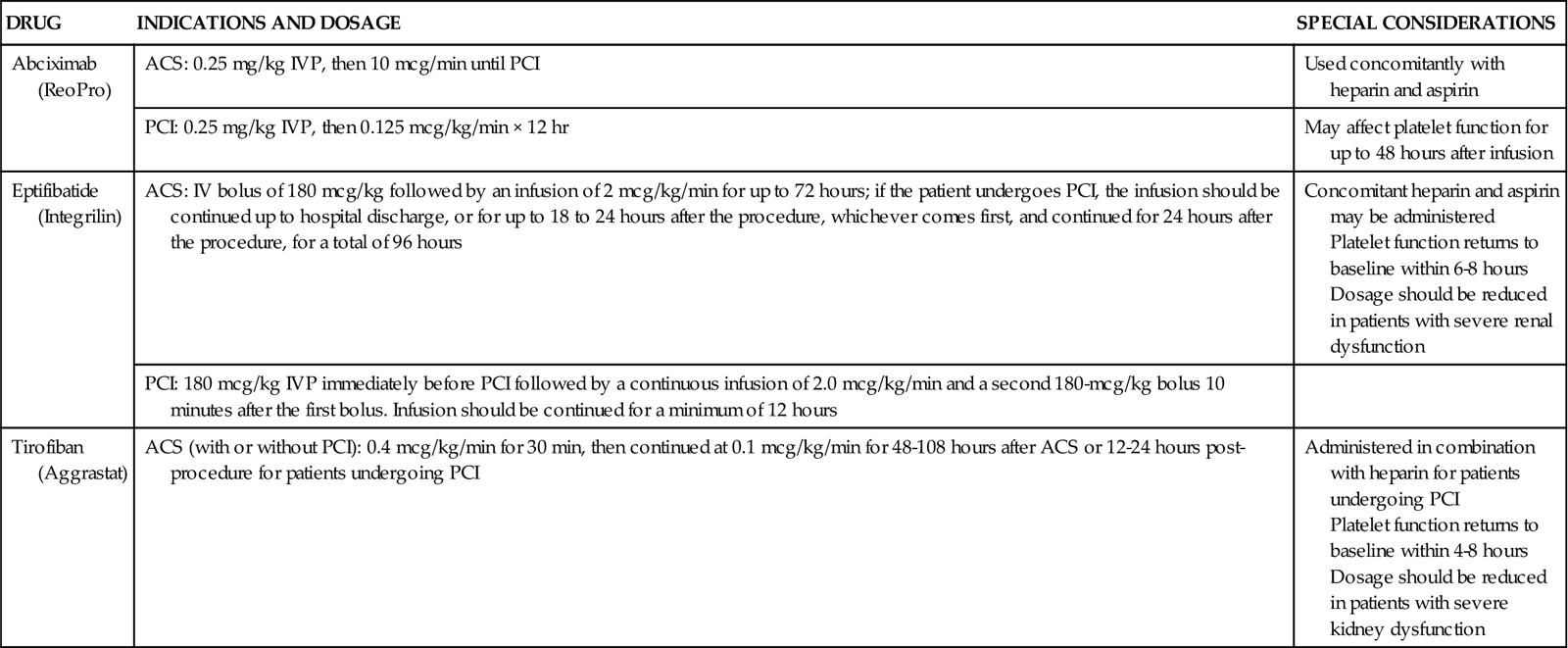
Specific interventions are used to prevent subacute stent thrombosis. High-pressure balloon inflations within the stent are employed to fully open the stent within the vessel, so reduced anticoagulation is sufficient to maintain stent patency. Dual antiplatelet therapy (aspirin and thienopyridine) has been shown to be more important than anticoagulation in preventing stent thrombosis.36 These agents are administered before the procedure and continued at discharge.37 Two potent antiplatelet glycoprotein IIb/IIIa inhibitors, eptifibatide (Integrilin) and tirofiban (Aggrastat), also reduce the formation of intracoronary thrombosis and are used across the spectrum of interventional procedures, from PTCA to atherectomy to stenting.37 Indications and dosing of glycoprotein IIb/IIIa inhibitors are provided in Table 13-6.
TABLE 13-6
PHARMACOLOGICAL MANAGEMENT: GLYCOPROTEIN IIB/IIIA INHIBITORS
| DRUG | INDICATIONS AND DOSAGE | SPECIAL CONSIDERATIONS |
| Abciximab (ReoPro) | ACS: 0.25 mg/kg IVP, then 10 mcg/min until PCI | Used concomitantly with heparin and aspirin |
| PCI: 0.25 mg/kg IVP, then 0.125 mcg/kg/min × 12 hr | May affect platelet function for up to 48 hours after infusion | |
| Eptifibatide (Integrilin) | ACS: IV bolus of 180 mcg/kg followed by an infusion of 2 mcg/kg/min for up to 72 hours; if the patient undergoes PCI, the infusion should be continued up to hospital discharge, or for up to 18 to 24 hours after the procedure, whichever comes first, and continued for 24 hours after the procedure, for a total of 96 hours | Concomitant heparin and aspirin may be administered Platelet function returns to baseline within 6-8 hours Dosage should be reduced in patients with severe renal dysfunction |
| PCI: 180 mcg/kg IVP immediately before PCI followed by a continuous infusion of 2.0 mcg/kg/min and a second 180-mcg/kg bolus 10 minutes after the first bolus. Infusion should be continued for a minimum of 12 hours | ||
| Tirofiban (Aggrastat) | ACS (with or without PCI): 0.4 mcg/kg/min for 30 min, then continued at 0.1 mcg/kg/min for 48-108 hours after ACS or 12-24 hours post-procedure for patients undergoing PCI | Administered in combination with heparin for patients undergoing PCI Platelet function returns to baseline within 4-8 hours Dosage should be reduced in patients with severe kidney dysfunction |
Drug-Eluting Stents
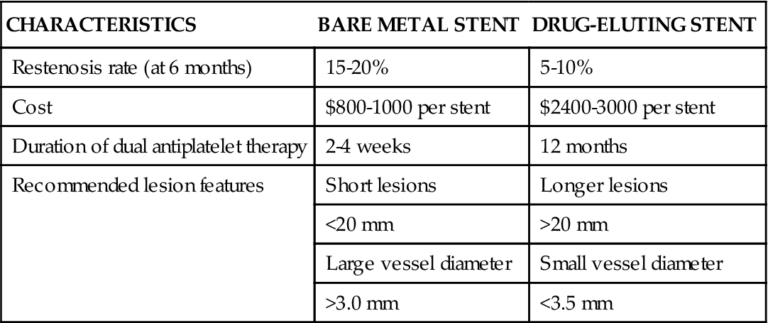
In an effort to minimize restenosis, drug-eluting stents (DES) were developed. These stents have polymer coatings impregnated with drugs that are released slowly into the endothelium at the site of stent placement to inhibit cellular proliferation. DES coated with sirolimus (an immunosuppressive drug used to prevent organ transplant rejection) and paclitaxel (an anticancer agent) have been approved by the FDA.38 In initial trials, DES were found to decrease the 6-month restenosis rate to less than 10%, and they soon became the predominant stent, implanted in 90% of patients. Some trials demonstrated similar efficacy between bare metal stents and DES in long-term outcomes (stent thrombosis, MI, or death) and raised concerns regarding the possibility of late stent thrombosis (>1 year) in DES.39,40 As a result, DES usage has decreased somewhat to between 60% and 70% of patients.30 Because a DES delays endothelialization, dual antiplatelet therapy must be continued for a longer period to prevent stent thrombosis. A DES is also considerably more expensive than a bare metal stent. A comparison of bare metal stents and DES is provided in Table 13-7.
TABLE 13-7
COMPARISON OF BARE METAL AND DRUG-ELUTING STENTS
| CHARACTERISTICS | BARE METAL STENT | DRUG-ELUTING STENT |
| Restenosis rate (at 6 months) | 15-20% | 5-10% |
| Cost | $800-1000 per stent | $2400-3000 per stent |
| Duration of dual antiplatelet therapy | 2-4 weeks | 12 months |
| Recommended lesion features | Short lesions | Longer lesions |
| <20 mm | >20 mm | |
| Large vessel diameter | Small vessel diameter | |
| >3.0 mm | <3.5 mm |
PCI Complications
Acute Complications
The incidence of serious cardiac complications after PCI, including coronary spasm, coronary artery dissection, and acute coronary thrombosis, has decreased significantly with improvements in technology. Stents have proved efficacious in the repair of coronary dissections, decreasing the need for emergency bypass surgery. Acute thrombosis has decreased with the use of glycoprotein IIb/IIIa inhibitors (see Table 13-6). Other complications that can occur in the period immediately after PCI include bleeding and hematoma formation at the site of vascular cannulation, compromised blood flow to the involved extremity, retroperitoneal bleeding, contrast-induced kidney failure, dysrhythmias, and vasovagal response (hypotension, bradycardia, and diaphoresis) during manipulation or removal of introducer sheaths.
Late Complications
Restenosis after PCI continues to be a problem, although rates are much lower with DES than with angioplasty alone. Patients at greatest risk are those with complex lesions, multivessel disease, or diabetes.41 Treatment options for in-stent restenosis include balloon dilation, debulking with an atherectomy device, implantation of another DES or brachytherapy—the localized delivery of intracoronary radiation through specialized catheters. Because healing within the stent is delayed, late thrombosis may occur in patients with DES. Late thrombosis, although rare, is associated with a 45% mortality rate. Premature discontinuation of antiplatelet therapy is the strongest predictor of late stent thrombosis, especially with DES.32
Nursing Management
Nursing management after PCI is focused on accurate assessment of the patient’s condition and prompt intervention. Nursing priorities are directed toward (1) monitoring for recurrent angina, (2) protecting kidney function, (3) monitoring the femoral access site, (4) monitoring peripheral pulses, promoting mobility, and (5) providing patient education.
Monitoring for Recurrent Angina
It is essential that the nurse observe the patient for recurrent angina or ST elevation, which are clinical indicators of myocardial ischemia. Monitoring leads should be selected that will reflect ischemia in the vessels that were treated during the intervention.29 Angina during interventional cardiology procedures is an expected occurrence at the time of balloon inflation or manipulation within the coronary artery. Intraprocedural angina is caused by the temporary interruption of blood flow through the involved artery, which should subside with deflation or removal of the balloon or nitroglycerin administration, or both. Angina after a coronary interventional procedure may be caused by transient coronary vasospasm, or it may signal a more serious complication—acute thrombosis. In any case, the nurse must act quickly to assess for manifestations of myocardial ischemia and initiate clinical interventions as indicated. The physician usually orders intravenous nitroglycerin to be titrated to alleviate chest pain. Continued angina despite maximal vasodilator therapy usually rules out transient coronary vasospasm as the source of ischemic pain, and a return to the cardiac catheterization laboratory must be considered.
Protecting Kidney Function
Patients undergoing PCI are exposed to significant amounts of contrast dye, with its associated nephrotoxicity. Renal protective strategies may be implemented before the procedure, especially for patients with evidence of baseline impairment of kidney function. This may include preprocedural hydration, infusion of sodium bicarbonate, and administration of N-acetylcysteine (Mucomyst).42 After PCI, hydration is essential to maintain adequate flow through the kidneys. Intravenous fluids are administered, and patients are encouraged to take oral fluids as tolerated.43
Monitoring the Femoral Access Site
Assessing for Bleeding
While the femoral sheath is in place or after its removal, bleeding or hematoma at the sheath insertion site may occur due to the effects of anticoagulation. The nurse observes the patient for bleeding or swelling at the puncture site and frequently assesses adequacy of circulation to the involved extremity. The nurse also assesses the patient for back pain, which can indicate retroperitoneal bleeding from the internal arterial puncture site. The patient is instructed to keep the involved leg straight and not to elevate the head of the bed any more than 30 degrees while the sheath is in place (to prevent dislodgment) and for several hours after its removal (to prevent bleeding), unless a vascular closure device is used. After sheath removal, direct pressure is applied to the puncture site for 15 to 30 minutes; a sandbag may be ordered if direct pressure is inadequate for hemostasis. For stent placement or atherectomy, which require a larger sheath size, a C-clamp or femoral compression device may be used to apply continuous pressure for 1 to 2 hours to ensure adequate hemostasis.
Hemostatic Devices
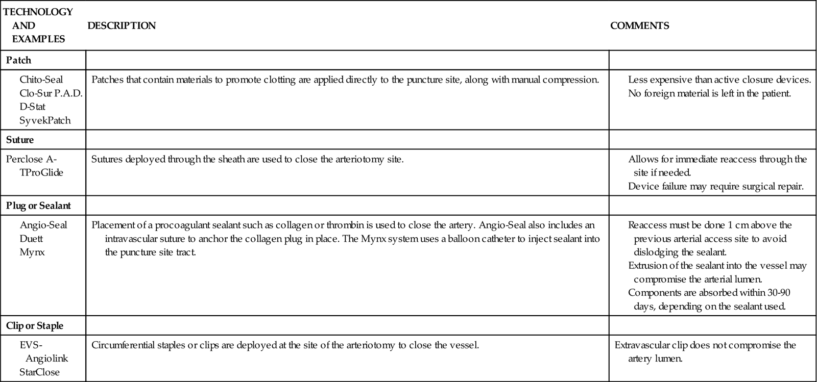
In the last decade, percutaneous vascular hemostatic devices have been introduced to address the problem of achieving adequate hemostasis at the femoral access site after sheath removal. Active closure devices utilize mechanical sutures, collagen plugs, or metal clips to close the vessel when the sheath is removed. Advantages of these devices include a reduced time to hemostasis of less than 5 minutes regardless of the patient’s level of anticoagulation, earlier ambulation, and increased patient comfort.44 Perclose has marketed a percutaneous vascular surgical device that is inserted into the femoral artery in the same position as a conventional introducer sheath. The device contains needles and sutures that are used to suture the artery closed after the interventional procedure. Angio-Seal is a vascular hemostatic device that uses a collagen plug to seal the arterial puncture site. Gentle pressure is maintained over the puncture site for approximately 5 minutes, until hemostasis is achieved. The StarClose vascular closure device consists of a tiny circumferential nitinol (nickel and titanium) clip that is applied to the surface of the vessel to close the femoral artery at the end of the procedure.
Reports of complications and increased cost have limited the use of active closure devices by some clinicians.44,45 To avoid these complications, a number of products have been developed to enhance manual compression and shorten the time required to achieve hemostasis. Some of these devices rely on the delivery of prothrombotic materials by a patch, whereas others increase local pressure over the puncture site. These devices do not offer immediate closure, but may decrease the time to ambulation.44 A comparison of vascular closure systems is provided in Table 13-8.
TABLE 13-8
Monitoring Peripheral Pulses
Excessive bleeding or hematoma formation can become a serious problem if it results in hypotension or compromised blood flow to the involved extremity. Pulses are usually monitored every 15 minutes for the first 2 hours after the procedure and then every 1 to 2 hours until the sheaths are removed. After sheath removal, pulses are again monitored at 15-minute intervals for a brief period.
Promoting Mobility
Patients usually are allowed to resume ambulation 6 to 8 hours after the procedure, depending on institutional protocol, and effectiveness of hemostatic closure of the vascular access site.
Providing Patient Education
In most cases, patients undergoing elective angioplasty, atherectomy, or stent procedures are hospitalized for approximately 24 hours. All patients require education about their medication regimen and about risk-factor modification. Because of the abbreviated hospital stay, the nurse often has time to do little more than identify the offending risk factors and initiate basic instruction. Patients are referred to local cardiac rehabilitation centers for more extensive teaching and follow-up to facilitate understanding and compliance with risk-factor modification.
Another point of instruction that must be addressed is the patient’s knowledge deficit related to discharge medications. Patients are sent home on a regimen of antiplatelet drugs and drugs for secondary prevention, such as lipid-lowering agents and blood pressure medications. A nitrate such as isosorbide may be prescribed to promote vasodilation, or, if the patient has demonstrated evidence of a vasospastic component to the disease, calcium channel blockers may be used. It is essential that the patient clearly understand the rationale for therapy and the potential side effects of each drug. Patients also need to understand the importance of not discontinuing their antiplatelet therapy; deaths have been reported when patients discontinued this therapy before elective procedures.46 It is important that patients be provided with written information and a number to call if problems occur.
Percutaneous Valve Repair
Percutaneous catheter technology has also been adapted to allow for nonsurgical interventions for stenotic cardiac valves. Percutaneous balloon valvuloplasty, also known as balloon valvotomy, has become an accepted alternative to surgical approaches in patients with mitral or pulmonic valve stenosis. Aortic valvotomy has a limited role in adults, because restenosis and clinical deterioration occur within 6 to 12 months in most patients, and the procedure is associated with significant morbidity and mortality.47 Eligibility criteria for balloon valvuloplasty are listed in Box 13-5.
Balloon valvotomy is performed in the cardiac catheterization laboratory. The procedure is similar to a routine cardiac catheterization, including cannulation of the femoral artery and vein with percutaneous introducer sheaths. The balloon dilation catheter is then threaded over a guidewire across the stenotic valvular orifice. The valves may be approached retrograde through the aorta, or antegrade across the interatrial septum. In the antegrade transseptal approach, the balloon catheter is passed across the interatrial septum, which results in the creation of a small atrial septal defect.48 Subsequent inflations of the balloon increase the valve opening by separating fused valve leaflets, cracking calcified leaflets, and stretching valve structures. Inflations are continued until the balloon “waist” disappears, which indicates full inflation. Regurgitant flow can result, particularly after mitral valvotomy, and may result in the need for emergent valve replacement if severe. The risks of balloon valvotomy are similar to those inherent in most catheterization procedures and include cardiac perforation, thromboembolic events, dysrhythmias, and vascular complications caused by the sheath. Postprocedural nursing management is similar to that for other percutaneous cardiac catheter procedures.
A number of additional percutaneous procedures for valve repair are being evaluated in clinical trials. Percutaneous aortic valve replacement has shown promising results as a possible treatment for aortic stenosis. This procedure involves the use of a valvuloplasty balloon catheter to deliver a stainless steel stent with an attached bovine valve within the native aortic valve. After the stent is in position, the balloon is inflated to deploy the stent valve.49 Investigational percutaneous treatments for mitral valve repair include correction of mitral regurgitation with a leaflet clip or an annular ring.50
Cardiac Surgery
Nursing management of the patient undergoing cardiac surgery is demanding but exciting work that requires the talents of an experienced team of critical care nurses. The following discussion introduces basic cardiac surgical techniques and principles of cardiopulmonary bypass and highlights the key points about postoperative care of the adult patient who requires valve replacement or coronary artery revascularization.
Coronary Artery Bypass Surgery
Since its introduction more than 2 decades ago, CABG has proved to be safe and effective in relieving uncontrolled angina pectoris in most patients. Information on coronary artery disease is presented in Chapter 12 and catheter interventions for coronary artery disease are discussed earlier in this chapter.
The combined results of three major randomized trials support the view that CABG affords dramatic improvement of symptoms and quality of life. CABG is more effective than medical therapy (i.e., pharmacological therapy and PCI) for improving survival in patients with left main coronary artery disease, triple-vessel disease, or double-vessel disease involving the LAD artery, and for relief of exercise-induced ischemia or chronic ischemia leading to LV dysfunction. Medical therapy is recommended if the ischemia is prevented by antianginal drugs that are well tolerated by the patient.51 Surgical revascularization has been shown to be more efficacious than stenting in patients with multivessel disease.52 If arterial grafts are used, CABG has superior long-term patency rates, surpassing those of angioplasty or stents.53 Bypass surgery may allow for more complete revascularization, because it can be used on vessels that are not amenable to treatment with a percutaneous approach, such as those with total occlusions or excessive tortuosity.
Myocardial revascularization involves the use of a conduit, or channel, designed to bypass an occluded coronary artery. The two most common conduits are the saphenous vein graft and the internal mammary artery (IMA) graft.
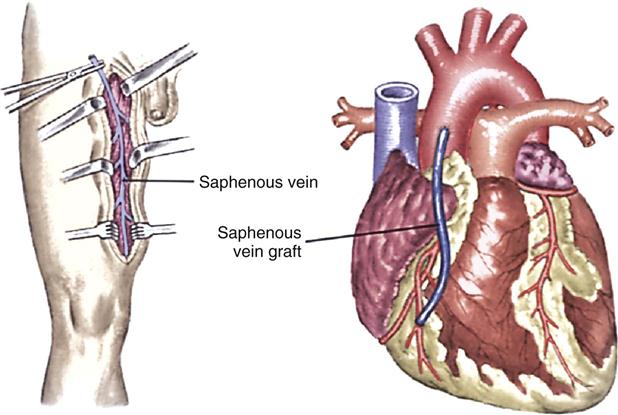
Saphenous Vein Graft
Saphenous vein grafting involves the anastomosis of an excised portion of the saphenous vein proximal to the aorta and distal to the coronary artery below the obstruction (Figure 13-11). Traditionally, the saphenous vein graft was obtained through an open incision, but endoscopic harvesting of this vessel is now possible. This minimally invasive technique of graft procurement decreases postoperative pain and reduces leg wound infection.54
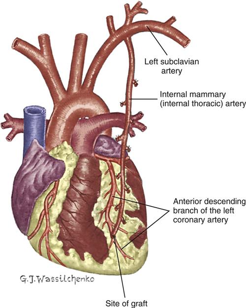
Internal Mammary Artery Graft
The IMA, which usually remains attached to its origin at the subclavian artery, is swung down and anastomosed distal to the coronary artery (Figure 13-12). Either the right IMA or the left IMA may be used as a conduit. Of note, emergency CABG may preclude the use of the IMA because of the extra time required to mobilize the artery and the inability to effect cardioplegia through this conduit. However, the current trend is to use arterial conduits such as the IMA whenever possible, because their long-term patency rates are superior to those of the saphenous vein graft.55
Right Gastroepiploic Artery Graft
The right gastroepiploic artery (GEA) has also been introduced as an alternative conduit for CABG. The artery, which is a branch of the gastroduodenal artery, is pulled up through the diaphragm to the pericardial cavity, and anastomosed to a distal portion of the coronary artery. Although it is a little smaller in diameter than the IMA, studies indicate that patency rates are excellent.56 Because of its size and anatomic location, the gastroepiploic artery is well suited for bypassing the right coronary artery, the circumflex artery, or the posterior descending artery. However, the technical aspects of obtaining this conduit may limit its widespread use.
Radial Artery Grafts
The potential benefit of long-term patency associated with arterial conduits has revived interest in the use of radial artery grafts. First introduced as a potential conduit for myocardial revascularization in the 1970s, radial artery grafts were abandoned because of a high incidence of early graft occlusion and vasospasm. Current early patency rates of 90% or better have been attributed to improved harvesting techniques and the use of postoperative calcium channel blockers to minimize vasospasm.57 A comparison of conduits used for myocardial revascularization is provided in Table 13-9.
TABLE 13-9
CONDUITS USED FOR CORONARY ARTERY BYPASS GRAFTS

Valvular Surgery
Valvular disease results in various hemodynamic dysfunctions that usually can be managed medically as long as the patient remains symptom-free. There is reluctance to intervene surgically early in the course of this disease because of the surgical risks and long-term complications associated with prosthetic valve replacement. These consequences, however, must be weighed against the possibility of irreversible deterioration in LV function that may develop during the compensated asymptomatic phase (see “Valvular Heart Disease” in Chapter 12).
Surgical therapy for aortic valve disease consists primarily of aortic valve replacement, although repairs may be done for selected regurgitant valves.48 Three surgical procedures are available to treat mitral valve disease: commissurotomy, valve repair, and valve replacement. Commissurotomy is performed for mitral stenosis; the fused leaflets are incised, and calcium deposits are débrided to increase valve mobility. Repair of damaged leaflets may be accomplished with pericardial patches. In the setting of mitral regurgitation, valve repair may include reshaping of the leaflets and the use of a ring to reduce the size of the dilated mitral annulus, enhancing leaflet coaptation (annuloplasty). Although it is technically more demanding, valve repair is preferred over replacement to avoid the complications inherent with a prosthetic valve: the risk of thromboembolic events and the need for long-term anticoagulation.58 If reconstruction of the mitral valve is not possible, it is replaced.
The patient undergoing valvular surgery has an anticipated length of hospital stay from 5 to 9 days. The longer length of stay is for patients who undergo cardiac catheterization in addition to valvular surgery. Prosthetic heart valves are designed with an orifice, through which blood flows, and an occluding structure that opens and closes. The two categories of prosthetic heart valves are mechanical valves and biological valves, also described as tissue valves. Mechanical valves are made from combinations of metal alloys, Pyrolite carbon, Dacron, and Teflon, and have rigid occluding devices (Figure 13-13). Their construction renders them highly durable, but all patients with mechanical valves require anticoagulation to reduce the incidence of thromboembolism.59 Biological valves are constructed from animal or human cardiac tissue and have flexible occluding mechanisms. Because of their low thrombogenicity, tissue valves offer the patient freedom from therapeutic anticoagulation. Their durability, however, is limited by their tendency toward early calcification. Box 13-6 provides a description of various valvular prostheses.
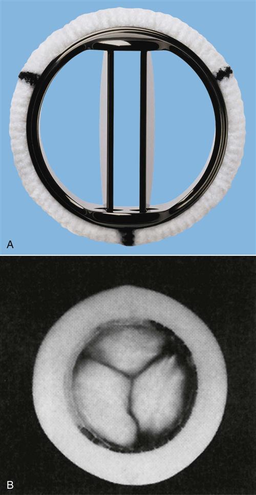
A, The St Jude Medical mechanical heart valve is a mechanical central-flow disk. B, In the Hancock II porcine aortic valve, the flexible Delrin stent and sewing ring are covered in Dacron cloth. (A, Courtesy St Jude Medical, Inc., copyright 1993, St Paul, Minn; B, from Eagle K, et al, editors: The practice of cardiology, ed 2, Boston, 1989, Little, Brown.)
Heart Transplant
Heart transplant is performed for end-stage heart failure with a life expectancy of only 6 to 12 months.60 A median incision and sternotomy is for visualization of the thorax. All of the diseased heart is removed except the posterior walls of the atria that contain the openings of the pulmonary veins and the vena cava. There are four major anastomoses to connect the donor heart to the remaining atrial wall. The right atria, left atria, aorta, and pulmonary artery are connected in that order (Figure 13-14). Immediate postoperative management is similar to other cardiac surgical procedures. For the rest of their lives, recipients must take immunosuppressive drugs to prevent rejection of the new heart.61 Surveillance for rejection, prevention of infection, and comprehensive education about transplant self-care are essential to ensure a long-term success.
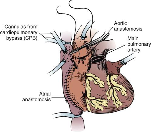
Cardiopulmonary Bypass
Cardiopulmonary bypass (CPB) is a mechanical means of circulating and oxygenating a patient’s blood while diverting most of the circulation from the heart and lungs during cardiac surgical procedures. Numerous clinical sequelae can result from CPB (Table 13-10). Knowledge of these effects allows the nurse to anticipate problems and intervene effectively.
TABLE 13-10
PHYSIOLOGICAL EFFECTS OF CARDIOPULMONARY BYPASS
| EFFECTS | CAUSES |
| Intravascular fluid deficit (hypotension) | Third-spacing |
| Postoperative diuresis | |
| Sudden vasodilation (drugs, rewarming) | |
| Third-spacing (weight gain, edema) | Decreased plasma protein concentration |
| Increased capillary permeability | |
| Myocardial depression (decreased cardiac output) | Hypothermia |
| Increased systemic vascular resistance | |
| Prolonged cardiopulmonary bypass pump run | |
| Preexisting heart disease | |
| Inadequate myocardial protection | |
| Coagulopathy (bleeding) | Systemic heparinization |
| Mechanical trauma to platelets | |
| Depressed release of clotting factors from liver as a result of hypothermia | |
| Pulmonary dysfunction (decreased lung mechanics and impaired gas exchange) | Decreased surfactant production |
| Pulmonary microemboli | |
| Interstitial fluid accumulation in lungs | |
| Hemolysis (hemoglobinuria) | Red blood cells damaged in pump circuit |
| Hyperglycemia (rise in serum glucose concentration) | Decreased insulin release |
| Stimulation of glycogenolysis | |
| Hypokalemia (low serum potassium concentration) | Intracellular shifts during bypass and postoperative diuresis |
| Hypomagnesemia (low serum magnesium concentration) | Postoperative diuresis resulting from hemodilution |
| Neurological dysfunction (decreased level of consciousness, motor/sensory deficits) | Inadequate cerebral perfusion |
| Microemboli to brain (air, plaque fragments, fat globules) | |
| Hypertension (transient rise in blood pressure) | Catecholamine release and systemic hypothermia causing vasoconstriction |
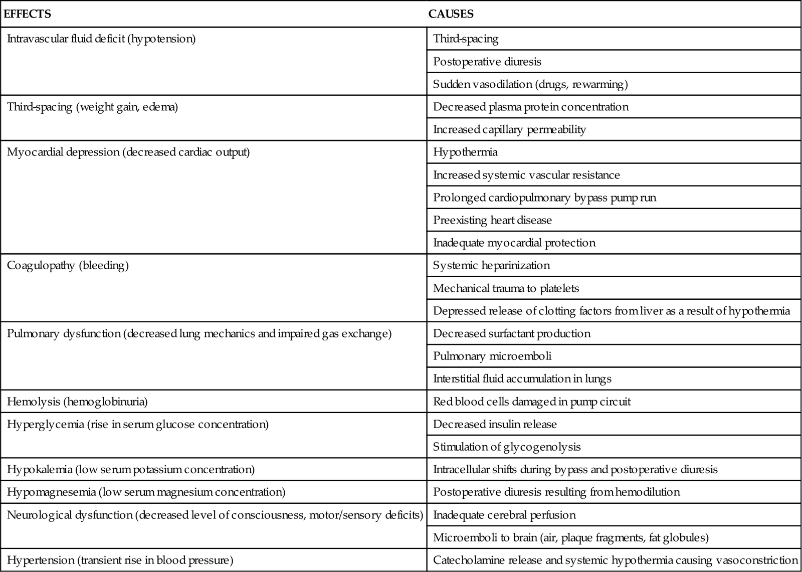
Nursing Management
Nursing priorities are directed toward (1) optimizing cardiac output, (2) temperature regulation, (3) controlling bleeding, (4) maintaining chest tube patency, (5) recognizing cardiac tamponade, (6) promoting early extubation, (7) assessing for neurological complications, (8) preventing infection, (9) preserving kidney function, and (10) providing patient education.
Optimizing Cardiac Output
Postoperative cardiovascular support often is indicated because of a low-output state resulting from preexisting heart disease, a prolonged cardiopulmonary bypass pump run, inadequate myocardial protection, or some combination of these factors. Cardiac output can be maximized by adjustments in heart rate, preload, afterload, and contractility.
Heart Rate
In the presence of low cardiac output, the heart rate can be appropriately regulated by means of temporary pacing or drug therapy. Temporary epicardial pacing usually is instituted when the heart rate of the adult patient who has had cardiac surgery drops to less than 80 beats/min. In the case of tachycardia, intravenous beta-blockers (esmolol) or calcium channel blockers (diltiazem) may be used in the acute postoperative period to slow supraventricular rhythms with a ventricular response that exceeds 110 beats/min. Because ventricular ectopy can result from hypokalemia, serum potassium levels are maintained in the high-normal range (4.5 to 5 mEq/L) to provide some margin for error. Maintaining serum magnesium in a therapeutic range (2 mEq/L) has also been shown to reduce the incidence of dysrhythmias in the postoperative period.62
Atrial fibrillation occurs in one third of patients after cardiac surgery, with a peak occurrence in the first 2 to 3 days after surgery. This rhythm may induce hemodynamic compromise, prolong hospitalization, and increase the patient’s risk of stroke. Prophylactic administration of antidysrhythmic agents such as beta-blockers has been shown to decrease the incidence of atrial fibrillation and its clinical sequelae.63
Preload
In most patients, reduced preload is the cause of low postoperative cardiac output. If a pulmonary artery catheter has been inserted during surgery, monitoring of the pulmonary artery occlusion pressure (PAOP), also known as the wedge pressure, can provide a more convenient and accurate guide to LV preload than monitoring of central venous pressure (CVP) alone. To enhance preload, volume may be administered in the form of crystalloid, colloid, or packed red cells. It is not uncommon to achieve the greatest hemodynamic stability in cardiac surgery patients when filling pressures (PAOP or pulmonary artery diastolic pressure [PADP]) are in the range of 18 to 20 mm Hg (normally 5 to 12 mm Hg).
Afterload
Partly as a result of the peripheral vasoconstrictive effects of hypothermia, many patients who have had cardiac surgery demonstrate postoperative hypertension. Although it is transient, postoperative hypertension can precipitate or exacerbate bleeding from the mediastinal chest tubes. The high SVR (afterload) resulting from the intense vasoconstriction can increase LV workload. Vasodilator therapy with intravenous sodium nitroprusside or nitroglycerin often is used to reduce afterload, control hypertension, and improve cardiac output.
A significant percentage of patients experience hypotension after cardiopulmonary bypass, associated with peripheral vasodilation and a low SVR. This is believed to occur, in part, because of the systemic inflammatory response to cardiopulmonary bypass. Therapy for hypotension after cardiac surgery usually includes volume loading and vasopressors such as phenylephrine or vasopressin to tighten the peripheral vasculature and maintain an adequate mean arterial pressure.64
Contractility
If the adjustments in heart rate, preload, and afterload fail to produce significant improvement in cardiac output, contractility can be enhanced with positive inotropic support or intraaortic balloon pumping (IABP) to augment circulation (discussed later).
Temperature Regulation
Hypothermia can contribute to depressed myocardial contractility in the patient who has had cardiac surgery. Hypothermia may contribute to postoperative bleeding, because the functioning of clotting factors is depressed during hypothermia. After surgery, patients may be rewarmed with the use of warmed air or water blankets. To prevent subsequent excessive temperature elevations, care must be taken to remove the blankets promptly when the body temperature reaches 98.6° F (37° C).
Controlling Bleeding
Postoperative bleeding from the mediastinal chest tubes can be caused by inadequate hemostasis, disruption of suture lines, or coagulopathy associated with cardiopulmonary bypass or hypothermia. Bleeding is more likely to occur with IMA grafts as a result of the extensive chest wall dissection required to free the IMA. If bleeding in excess of 150 mL/hr occurs early in the postoperative period, clotting factors (fresh-frozen plasma, fibrinogen, and platelets) and additional protamine (used to reverse the effects of heparin) may be administered, along with prompt blood replacement. Other medications used in the treatment of postoperative bleeding are described in Table 13-11.
TABLE 13-11
PHARMACOLOGICAL MANAGEMENT: POSTOPERATIVE BLEEDING
| DRUG | DOSAGE | ACTION AND SIDE EFFECTS |
| Aminocaproic acid (Amicar) | Loading dose: 5 g over 1 hour, followed by continuous infusion of 1 g/hr for 8 hr or until bleeding is controlled | Inhibits conversion of plasminogen to plasmin to prevent fibrinolysis, helping to stabilize clots |
| Desmopressin acetate (DDAVP) | 0.3 mg/kg IV over 20-30 minutes | Improves platelet function by increasing levels of factor VIII side effects include facial flushing, tachycardia, headache, and hypotension |
| Protamine sulfate | 25-50 mg IV slowly over 10 minutes | Neutralizes the anticoagulant effect of heparin Can cause hypotension, bradycardia, and allergic reactions |
Autotransfusion devices, which facilitate the collection and reinfusion of shed mediastinal blood, were used in some institutions in the past. Routine autotransfusion of shed mediastinal blood is no longer recommended, because it may further exacerbate bleeding by activating the extrinsic clotting pathway and increase the risk of infection.65 The use of positive end-expiratory pressure (PEEP) in conjunction with mechanical ventilation may be helpful in controlling excessive bleeding in some cases by increasing the intrathoracic pressure enough to effect tamponade of oozing mediastinal blood vessels.65 Rewarming the patient reverses the depressed manufacture and release of clotting factors that results from hypothermia. However, persistent mediastinal bleeding—usually in excess of 500 mL in 1 hour or 300 mL/hr for 2 consecutive hours despite normalization of clotting studies—is an indication for reexploration of the surgical site.
Maintaining Chest Tube Patency
Chest tube stripping to maintain patency of the tubes is controversial because of the high negative pressure generated by routine methods of stripping. It is believed to result in tissue damage that can contribute to bleeding. This risk must be carefully weighed against the real danger of cardiac tamponade if blood is not effectively drained from around the heart. Chest tube stripping often is advocated in instances of excessive postoperative bleeding. However, the technique of “milking” the chest tubes is advisable for routine postoperative care, because this technique generates less negative pressure and decreases the risk of bleeding.
Recognizing Cardiac Tamponade
Cardiac tamponade may occur after surgery if blood accumulates in the mediastinal space, impairing the heart’s ability to pump. Signs of tamponade include elevated and equalized filling pressures (e.g., CVP, PADP, PAOP), decreased cardiac output, decreased blood pressure, jugular venous distention, pulsus paradoxus, muffled heart sounds, sudden cessation of chest tube drainage, and a widened cardiac silhouette on chest x-ray films. Interventions for tamponade may include emergency sternotomy in the intensive care unit or a return to the operating room for surgical evacuation of the clot.
Promoting Early Extubation
Until recently, overnight intubation to facilitate lung expansion and optimize gas exchange was common for patients who had undergone cardiac surgery. Newer protocols that facilitate early extubation (within the first 4 to 8 hours) have been implemented in most institutions.66 Early extubation requires a multidisciplinary approach that incorporates anesthesiologists, surgeons, nurses, and respiratory therapists. Potential candidates must be identified before surgery so that the anesthetic regimen can be modified to support early extubation. One approach is to use short-acting anesthetic agents such as propofol (Diprivan) at the end of the surgery and to minimize the use of opioids. Another option is to administer neostigmine and glycopyrrolate at the end of the surgery to reverse the neuromuscular blockade used during the procedure.
After surgery, patients are evaluated for hemodynamic stability, adequate control of bleeding, and normothermia. After these criteria have been met, the patient is weaned off propofol or given neuromuscular reversal agents, and ventilator weaning can begin. If needed, opioids are given in small increments to manage pain and anxiety. Patients who exhibit hemodynamic instability or intraoperative complications or who have underlying pulmonary disease related to long-term valvular dysfunction may require longer periods of mechanical ventilation. After extubation, supplemental oxygen is administered, and patients are medicated for incisional pain to facilitate adequate coughing and deep breathing.
Assessing for Neurological Complications
The transient neurological dysfunction often seen in patients who have had cardiac surgery has been attributed to decreased cerebral perfusion, cerebral microemboli, and the systemic inflammatory response. It was once thought to be primarily caused by cardiopulmonary bypass, but newer evidence indicates that cognitive decline may be influenced more by patient-related factors such as the degree of preexisting cerebral vascular disease or diabetes.67 Compounding these are environmental factors such as sensory deprivation and sensory overload associated with being in a critical care unit. The term postcardiotomy delirium has been used to describe this postoperative syndrome that initially may manifest as only a mild impairment of orientation but that may progress to agitation, hallucinations, and paranoid delusions. One study indicated that mild preoperative cognitive impairment might be a useful predictor of who is likely to develop postcardiotomy delirium.68
Treatment of delirium may require the use of medications such as benzodiazepines or haloperidol (Haldol). Environmental modifications such as noise reduction, restoring normal day/night lighting patterns, and placing familiar objects at the bedside may help to calm and reorient the patient. Liberalization of visitation policies to allow family members a prolonged presence at the bedside is also highly desirable. Nursing management is organized to maximize optimal sleep patterns whenever possible.
Preventing Infection
Postoperative fever is fairly common after cardiopulmonary bypass. However, persistent temperature elevation to greater than 101° F (38.3° C) must be investigated. Sternal wound infections and infective endocarditis are the most devastating infectious complications, but leg wound infection, pneumonia, and urinary tract infection also can occur. Infection rates are greater in diabetic patients. Studies have shown that maintaining the blood glucose concentration between 80 and 110 mg/dL in the perioperative period by means of a continuous insulin infusion may decrease the risk of infection in this population.69
Preserving Kidney Function
Hemolysis caused by trauma to the red blood cells in the extracorporeal circuit results in hemoglobinuria, which can damage kidney tubules. Small amounts of furosemide (Lasix) usually are given to promote urine flow if the urine output is low (<25 to 30 mL/hr) and tinged pink.
Guidelines for Coronary Artery Bypass Grafting
The American College of Cardiology and the American Heart Association have developed a set of clinical practice guidelines for care of the patient undergoing CABG.51 These guidelines are designed to support clinical decision making with research evidence (Evidence-Based Collaborative Practice box on Coronary Artery Bypass Graft Surgery).
Providing Patient Education
Patient education includes information related to the surgical procedure, risk-factor management, and postoperative self-care. Patients who have undergone valve surgery may also require information regarding the need for antibiotic prophylaxis before invasive procedures and specific instructions pertaining to their anticoagulation regimen.
Minimally Invasive Cardiac Surgery
Over the past decade, new techniques have been developed to address some of the problems associated with traditional cardiac surgery procedures. Many of these procedures can be accomplished without a median sternotomy, by means of a series of holes, or ports, in the chest and small thoracotomy incisions. CABG or valve surgery is then performed using a thoracoscope for visualization and specially designed instruments.70 As technology has improved, minimally invasive procedures have become an option for an expanding number of patients.74 These procedures may be performed without cardiopulmonary bypass and are described as “off-pump” or “beating heart.” Other options are to use a less invasive, catheter-based system of cardiopulmonary bypass with access through the femoral artery and vein.70
OPCAB and MIDCABG
In an effort to avoid the adverse effects of cardiopulmonary bypass, off-pump coronary artery bypass (OPCAB) is performed in approximately 20% to 30% of cases.70 A variety of incisional approaches can be used. In minimally invasive direct coronary artery bypass graft (MIDCABG) surgery, a small left anterior thoracotomy incision is used to directly harvest the left IMA, which is then anastomosed to the LAD artery. Alternative approaches may use a segment of saphenous vein or radial artery, one end of which is attached to the left IMA and the other to accessible coronary arteries.70 Some surgeons may opt for a standard median sternotomy approach to allow for bypassing of distal vessels. Several techniques are used to stabilize the operative area during an OPCAB procedure. Immobilization devices that use compression or suction to create an immobile area have been developed to stabilize cardiac wall motion at the site of the anastomosis. Drugs that temporarily decrease the heart rate (e.g., esmolol, diltiazem) or cause transient cardiac asystole (e.g., adenosine) may also be used to further limit cardiac motion.71
Results from OPCAB surgery have been mixed. Some studies have demonstrated improvements in morbidity, including decreased transfusion requirements, shortened time on the ventilator, decreased length of stay, and a lower incidence of stroke and renal complications.72 Others have shown no advantage over conventional surgery.73,74 OPCAB may be most beneficial in patients with significant comorbid conditions and in those with contraindications to cardiopulmonary bypass.75
Minimally invasive procedures will continue to be refined with the use of robotic equipment in cardiac surgery, currently under clinical investigation at a small number of centers. Robotic-assisted surgery allows the surgeon to view a computer-enhanced image while manipulating instruments through small portholes using robotic arms. This provides increased surgical precision and the ability to perform conventional procedures with smaller incisions.70
Intraaortic Balloon Pump
IABP is the most widely used temporary mechanical circulatory assist device for supporting failing circulation (Box 13-7). Its therapeutic effects are based on the hemodynamic principles of diastolic augmentation and afterload reduction.
The most commonly used intraaortic balloon (IAB) catheter consists of a single, sausage-shaped polyurethane balloon that is wrapped around the distal end of a vascular catheter and positioned in the descending thoracic aorta just distal to the takeoff of the left subclavian artery. The second generation of IAB catheters is more flexible; they can be wrapped to a smaller diameter than their predecessors and therefore can be inserted into the femoral artery percutaneously rather than surgically. When attached to a bedside pumping console and properly synchronized to the patient’s cardiac cycle, the IAB inflates during diastole and deflates just before systole.
Initially, as the balloon is inflated in diastole concurrent with aortic valve closure, the blood in the aortic arch above the level of the balloon is displaced retrograde (backward) toward the aortic root, augmenting diastolic coronary arterial blood flow and increasing myocardial oxygen supply (Figure 13-15, A). The blood volume in the aorta below the level of the balloon is propelled forward toward the peripheral vascular system, which may enhance renal perfusion. Subsequently, the deflation of the balloon just before the opening of the aortic valve creates a potential space or vacuum in the aorta, toward which blood flows unimpeded during ventricular ejection (see Figure 13-15, B). This decreased resistance to LV ejection, or decreased afterload, facilitates ventricular emptying and reduces myocardial oxygen demands. The overall physiological effect of IABP therapy is an improvement in the balance between myocardial oxygen supply and demand. Contraindications to IABP include aortic aneurysm, aortic valve insufficiency, and severe peripheral vascular disease.76
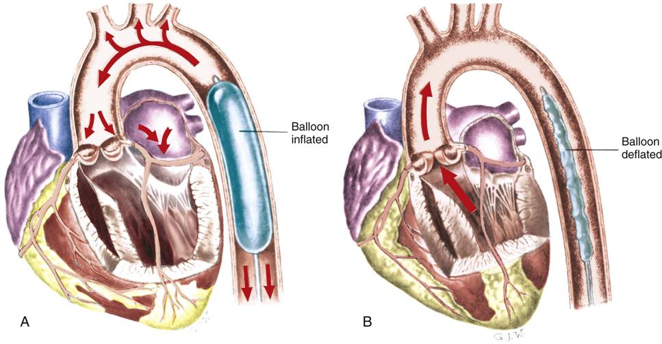
A, Diastolic balloon inflation augments coronary blood flow. B, Systolic balloon deflation decreases afterload.
Medical Management
The IAB may be inserted in the operating room, the cardiac catheterization laboratory, or the critical care unit. The IAB catheter is usually inserted percutaneously through the femoral artery and advanced to the correct position in the descending thoracic aorta. The physician may insert the balloon through an introducer sheath, or perform a sheathless insertion. The sheathless insertion decreases the degree of vessel occlusion created by the catheter. In the rare situation where percutaneous catheter placement is not feasible, the catheter can be placed through surgical cutdown or by a direct thoracic approach. After insertion, the balloon is attached to the console and filled with the prescribed volume of helium, and pumping is initiated. If the balloon fails to unwrap completely during filling, the physician may rapidly inflate and deflate the balloon manually, using a syringe.
Nursing Management
The management of the IAB pumping console and its timing functions may be performed by the nurse caring for the patient or delegated to specially trained personnel on the unit. In either situation, several important nursing management responsibilities relate to care of the patient receiving IABP therapy.
Preventing Dysrhythmias
The ECG and arterial pressure tracings are constantly monitored to verify the timing and effect of balloon counterpulsation. For counterpulsation to occur, the pump must receive a trigger signal to identify the beginning of a new cardiac cycle. The trigger can be the R wave of the ECG, the upstroke of the arterial pressure waveform, or a pacemaker spike.76 Dysrhythmias can adversely affect the timing of balloon inflation and deflation, so rhythm disturbances must be detected and treated promptly. Modern IABPs have automatic timing features that use internal algorithms to adjust inflation and deflation in response to changes in the patient’s heart rate or rhythm. New catheters are available that incorporate a fiberoptic sensor to enhance the quality of the arterial waveform obtained from the IAB catheter and improve timing. Mean arterial pressure is ideally maintained at approximately 80 mm Hg with adequate pumping.
Preventing Peripheral Ischemia
The most common complication of IABP support is lower extremity ischemia resulting from occlusion of the femoral artery by the catheter itself or by emboli caused by thrombus formation on the balloon.77 Although ischemic complications have decreased with sheathless insertion techniques and the introduction of smaller balloon catheters (7.5 versus 9.5 Fr), evaluation of peripheral circulation remains an important nursing assessment.78 The presence and quality of peripheral pulses distal to the catheter insertion site are assessed frequently, along with color, temperature, and capillary refill of the involved extremity. Doppler localization of peripheral pulses may be required if pulses are difficult to palpate on the cannulated extremity. Signs of diminished perfusion must be reported immediately. Anticoagulation (e.g., heparin infusion) may be prescribed to decrease the incidence of thrombosis. Other vascular complications associated with IABP include acute aortic dissection and the development of pseudoaneurysms at the catheter insertion site.
Monitoring for Balloon Complications
Another potential complication of IABP therapy is balloon perforation. Perforation occurs because of repeated contact of the balloon membrane with calcified plaque in the aorta as the balloon inflates and deflates. The patient is monitored for evidence of a balloon leak, such as a gas leak alarm from the pump console or the presence of blood in the IAB tubing. If a balloon leak is detected, pumping is stopped and the physician is immediately notified so that the balloon can be removed. If the balloon is not promptly removed or pumping is attempted after the perforation, the IAB may become entrapped as the blood hardens within the catheter, creating a mass. If this occurs, the balloon must be surgically removed.
Monitoring Balloon-Catheter Position
The balloon catheter must be maintained in proper position to optimize its effectiveness and minimize complications. The balloon may migrate proximally and occlude the left subclavian artery, which is detected clinically by a diminished left radial pulse; or the catheter may move distally, compromising circulation to the kidney, which is detected by a fall in urine output. If catheter displacement is suspected, x-rays of the chest or abdomen are obtained to verify balloon placement. Measures to prevent accidental displacement of the balloon catheter include ensuring that the patient observes complete bed rest, with the head of the bed elevated no more than 30 degrees, and avoids any flexion of the involved hip.
Preventing Complications
Log rolling, in which the patient is moved from side to side every 2 hours, is used to maintain skin integrity and to prevent pulmonary atelectasis. Some institutional protocols call for implementation of continuous lateral rotation therapy to help facilitate pulmonary toilet in the patient with an IABP. Because thrombocytopenia may occur as a result of mechanical destruction of the platelets by the pumping action of the balloon, platelet counts are closely monitored and the patient is observed for evidence of bleeding. Because infection of the insertion site is a potential complication, the dressing is changed in accordance with the hospital policy for other invasive lines.
Providing Psychological Support
The psychological needs of the patient must be considered while on IABP therapy. Sleep deprivation is common and is related in part to the continuous nursing management requirements for the patient and the noise level in the unit, including the sounds made by the balloon pumping device. Anxiety related to fear of non-recovery and loss of control because of forced immobility is a common occurrence.
Weaning from the IABP
Weaning from the IABP is considered after hemodynamic stability has been achieved with no, or only minimal, pharmacological support. One weaning procedure consists of slowly decreasing the pumping frequency from every beat to every eighth beat, as tolerated. Another weaning method involves a gradual decrease in balloon volume.79 To prevent thrombus formation on the balloon surface, the IABP must remain at a minimal pumping ratio (or volume) until its removal.
Pharmacological Management
Antidysrhythmic Drugs
Antidysrhythmic drugs comprise a diverse category of pharmacological agents used to terminate or prevent an array of abnormal cardiac rhythms. These drugs commonly are classified according to their primary effect on the action potential of cardiac cells (Figure 13-16). The classification scheme shown in Table 13-12 is the most commonly used system. Classification of newer agents is more difficult, because some of these agents have characteristics of more than one class and others have no characteristics of the current system.
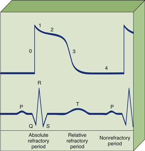
Phase 0, Depolarization with rapid influx of sodium. Phase 1, Rapid repolarization with rapid efflux of potassium ions and decreased sodium conductance. Phase 2, Plateau with slow influx of sodium and calcium ions. Phase 3, Repolarization with continued efflux of potassium ions. Phase 4, Resting phase with restoration of ionic balance by sodium and potassium pumps.
TABLE 13-12
CLASSIFICATION OF ANTIDYSRHYTHMIC AGENTS
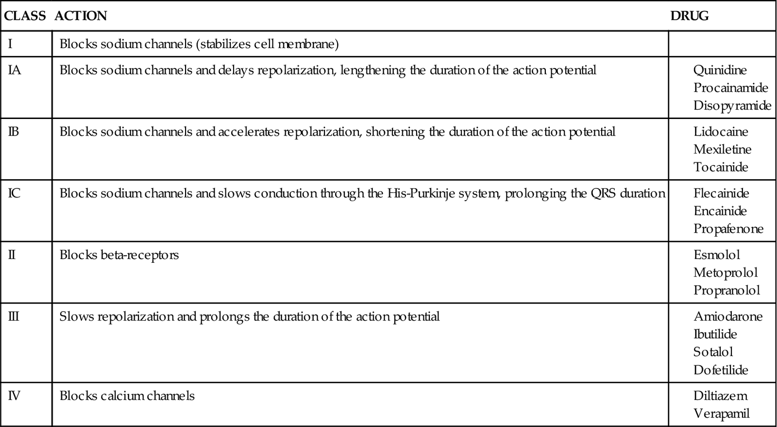
Class I Drugs
Class I agents are sodium channel blockers that decrease the influx of sodium ions through “fast” channels during phase 0 depolarization. This prolongs the absolute (effective) refractory period, thereby decreasing the risk of premature impulses from ectopic foci. These drugs also depress automaticity by slowing the rate of spontaneous depolarization of pacemaker cells during the resting phase (phase 4).
Class II Drugs
Class II drugs are β-adrenergic blockers (beta-blockers). They inhibit dysrhythmias mediated by the sympathetic nervous system by competing with endogenous catecholamines for available receptor sites. As a result, spontaneous depolarization during the resting phase (phase 4) is depressed, and AV conduction is slowed. Drugs in this class can be further subdivided into cardioselective agents (those that block only β1-receptors) and noncardioselective agents (those that block both β1– and β2-receptors). Knowledge of the effects of adrenergic-receptor stimulation allows for anticipation of both the therapeutic responses brought about by beta-blockade and the potential adverse effects of these agents (Table 13-13). For example, bronchospasm can be precipitated by noncardioselective beta-blockers in a patient with chronic obstructive pulmonary disease (COPD) caused by blockade of the effects of β2-receptors in the lungs. Beta-blockers also are negative inotropes and must be used cautiously in patients with LV dysfunction. Although numerous beta-blockers are marketed, only esmolol, metoprolol, and propranolol are available as intravenous agents for the treatment of acute dysrhythmias. Of these, esmolol (Brevibloc) offers significant advantages for the critically ill patient because of its short half-life (approximately 9 minutes). It is used in the treatment of supraventricular tachycardias, such as atrial fibrillation and atrial flutter.
TABLE 13-13
EFFECTS OF ADRENERGIC RECEPTORS
| RECEPTOR | LOCATION | RESPONSE TO STIMULATION |
| Alpha(α) | Vessels of skin, muscles, kidneys, and intestines | Vasoconstriction of peripheral arterioles |
| Beta1 (β1) | Cardiac tissue | Increased heart rate |
| Increased conduction | ||
| Increased contractility | ||
| Beta2 (β2) | Vascular and bronchial smooth muscle | Vasodilation of peripheral arterioles Bronchodilation |
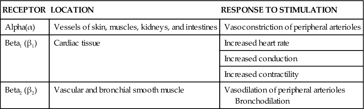
Class III Drugs
Class III agents include amiodarone, dofetilide, ibutilide, and sotalol. These agents markedly slow the rate of phase 3 repolarization, increasing the effective refractory period and the action potential duration. Although their effects on the action potential are similar, these drugs differ greatly in their mechanism of action and their side effects. At this time, sotalol is approved only for oral use. Intravenous amiodarone was originally approved for the treatment of serious ventricular dysrhythmias refractory to other medications. Because of its effectiveness, it is now used for both atrial and ventricular dysrhythmias.80 Dofetilide (Tikosyn) is a new class III antidysrhythmic agent used for the conversion to and maintenance of normal sinus rhythm in patients with highly symptomatic atrial fibrillation or atrial flutter. Because dofetilide prolongs the refractoriness of both atrial and ventricular tissue, prolongation of the QT interval can occur and is associated with an increased risk of torsades de pointes.81 Therapy with dofetilide is initiated in a hospital setting under close monitoring. Ibutilide (Covert) is a short-term antidysrhythmic agent used for the rapid conversion of acute atrial fibrillation or atrial flutter to sinus rhythm. The drug is administered as a 10-minute infusion in a carefully monitored clinical setting. The most serious side effect of ibutilide is its potential for inducing life-threatening dysrhythmias, especially torsades de pointes.82
Class IV Drugs
Class IV agents are calcium channel blockers that inhibit the influx of calcium through slow calcium channels during the plateau phase (phase 2). This effect occurs primarily in tissue in which slow calcium channels predominate, primarily the sinus and AV nodes and the atrial tissue. Verapamil was the first drug in this category available as an intravenous antidysrhythmic. It depresses sinus and AV node conduction and is effective in terminating supraventricular tachycardias caused by AV nodal reentry. Diltiazem (Cardizem) has become available in intravenous form and is thought to be as effective as verapamil in treating supraventricular dysrhythmias, with fewer hypotensive side effects. Because accessory pathways are not affected by calcium channel blockade, both of these agents must be avoided when treating atrial fibrillation in patients with Wolff-Parkinson-White syndrome.80
Unclassified Antidysrhythmics
Adenosine (Adenocard) is an antidysrhythmic agent that remains unclassified under the current system. Adenosine occurs endogenously in the body as a building block of adenosine triphosphate (ATP). Given in intravenous boluses, adenosine slows conduction through the AV node, causing transient AV block. It is used clinically to convert supraventricular tachycardias and to facilitate differential diagnosis of rapid dysrhythmias. Because of its short half-life, the drug is administered intravenously as a rapid bolus, followed by a saline flush. The bolus is delivered as centrally as possible, so that the drug reaches the heart before it is metabolized.80 Side effects are transient, because the drug is rapidly taken up by the cells and is cleared from the body within 10 seconds.
Magnesium is also unclassified under the present system. Although its action as an antidysrhythmic agent is not entirely understood, clinical studies suggest that it may reduce the incidence of both ventricular and supraventricular dysrhythmias in selected patient populations. It is considered the treatment of choice in patients with torsades de pointes. For acute treatment, 1 to 2 g of magnesium is administered over 1 to 2 minutes. In patients with confirmed hypomagnesemia, this bolus may be followed with a 24-hour infusion.80
Side Effects
Antidysrhythmic drugs carry the risk of serious side effects, some of which can be life threatening. The major side effects of the intravenous antidysrhythmic agents are listed in Table 13-14. The most severe complication is the potential for a prodysrhythmic effect. This may result in worsening of the underlying dysrhythmia, the occurrence of a new dysrhythmia, or the development of a bradydysrhythmia. For example, torsades de pointes is a prodysrhythmia caused by a number of drugs. Because the development of a prodysrhythmia is unpredictable, the nurse plays an important role in evaluating ECG changes, monitoring drug levels, and assessing patient symptoms. Antidysrhythmic agents may also alter the amount of energy required for defibrillation and pacing. For example, increases in the dose of an antidysrhythmic drug may increase the amount of output (mA) required to depolarize the myocardium.
TABLE 13-14
PHARMACOLOGICAL MANAGEMENT: SELECTED ANTIDYSRHYTHMIC AGENTS
| DRUG AND SITE OF ACTION | INDICATIONS | DOSAGE | MAJOR SIDE EFFECTS |
| Sinus Node, Atria, or AV Node | |||
| Adenosine | SVT, PSVT | 6 mg IV rapid push; if unsuccessful, repeat with 12 mg over 1-2 seconds; follow with IV fluid 10 mL flush (NS or D5W) | Transient; flushing, dyspnea, hypotension |
| Digoxin | AFib, AF, PSVT | 0.5-1 mg loading dose in divided doses; maintenance dose of 0.125-0.375 mg daily | Bradycardia, heart block Toxicity: CNS and GI symptoms |
| Diltiazem | SVT, AFib, AF | Bolus dose of 0.25 mg/kg IV over 2 minutes, followed by an infusion of 5-15 mg/hr | Bradycardia, hypotension, AV block |
| Esmolol | ST, SVT | Loading dose of 500 mcg/kg over 1 minute, followed by an infusion of 50 mcg/kg/min for 4 minutes; repeat procedure every 5 minutes, increasing infusion by 25-50 mcg/kg/min to maximum of 200 mcg/kg/min | Hypotension, bradycardia, heart failure |
| Ibutilide | AFib, AF | 0.010-0.025 mg/kg infused over 10 minutes (may repeat once) or 1 mg diluted in 50 mL infused over 10 minutes (may repeat once) | Minimal side effects except for rare polymorphic VT (torsades de pointes) |
| Propranolol | SVT | 1-3 mg IV every 5 minutes, not to exceed 0.1 mg/kg | Bradycardia, heart block, heart failure |
| Verapamil | AF, PSVT | 5-10 mg IV over 2 minutes, may repeat in 15-30 minutes | Hypotension, bradycardia, heart failure |
| Ventricle | |||
| Lidocaine | PVCs, VT, VF | 1-1.5 mg/kg bolus, followed by continuous infusion of 1-4 mg/min | CNS toxicity, nausea, vomiting with repeated doses |
| Atria and Ventricle | |||
| Amiodarone | VT/VT arrest | 300 mg IV push; may repeat with 150 mg in 3-5 minutes (maximum dose, 2.2 g/24 hr) | Hypotension, abnormal liver function tests |
| Stable VT, AFib, AF | 150 mg IV over 10 minutes, followed by 360 mg over 6 hours (1 mg/min); maintenance infusion of 0.5 mg/min | ||
| Procainamide | AF, SVT, PVCs, VT | Loading dose of 12-17 mg/kg at a rate of 20 mg/min, followed by infusion of 1-4 mg/min | Hypotension, GI effects Widening of QRS and QT lengthening |
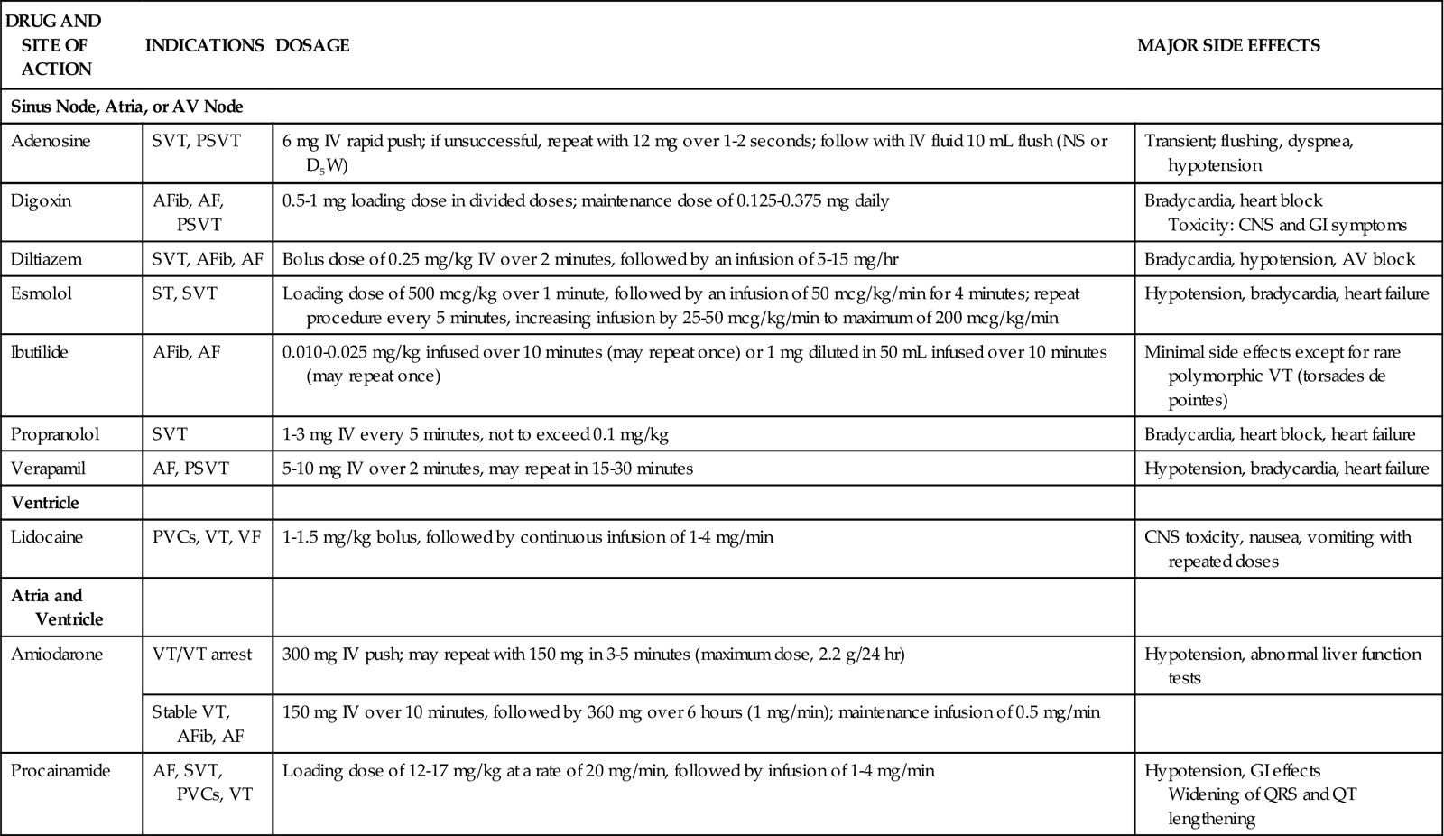
Treatment of Atrial Fibrillation
More than 2 million people in the United States have atrial fibrillation, and extensive research has been done on the treatment of this disorder. The goals of pharmacological therapy for atrial fibrillation include reestablishing and maintaining sinus rhythm, decreasing the rapid ventricular response during episodes of atrial fibrillation, and preventing the risk of thromboembolism. Table 13-15 reviews current drugs used in the treatment of atrial fibrillation. Results of some clinical trials suggest that rate control is equivalent to restoration of sinus rhythm in terms of mortality.82,83
TABLE 13-15
PHARMACOLOGICAL MANAGEMENT: ATRIAL FIBRILLATION
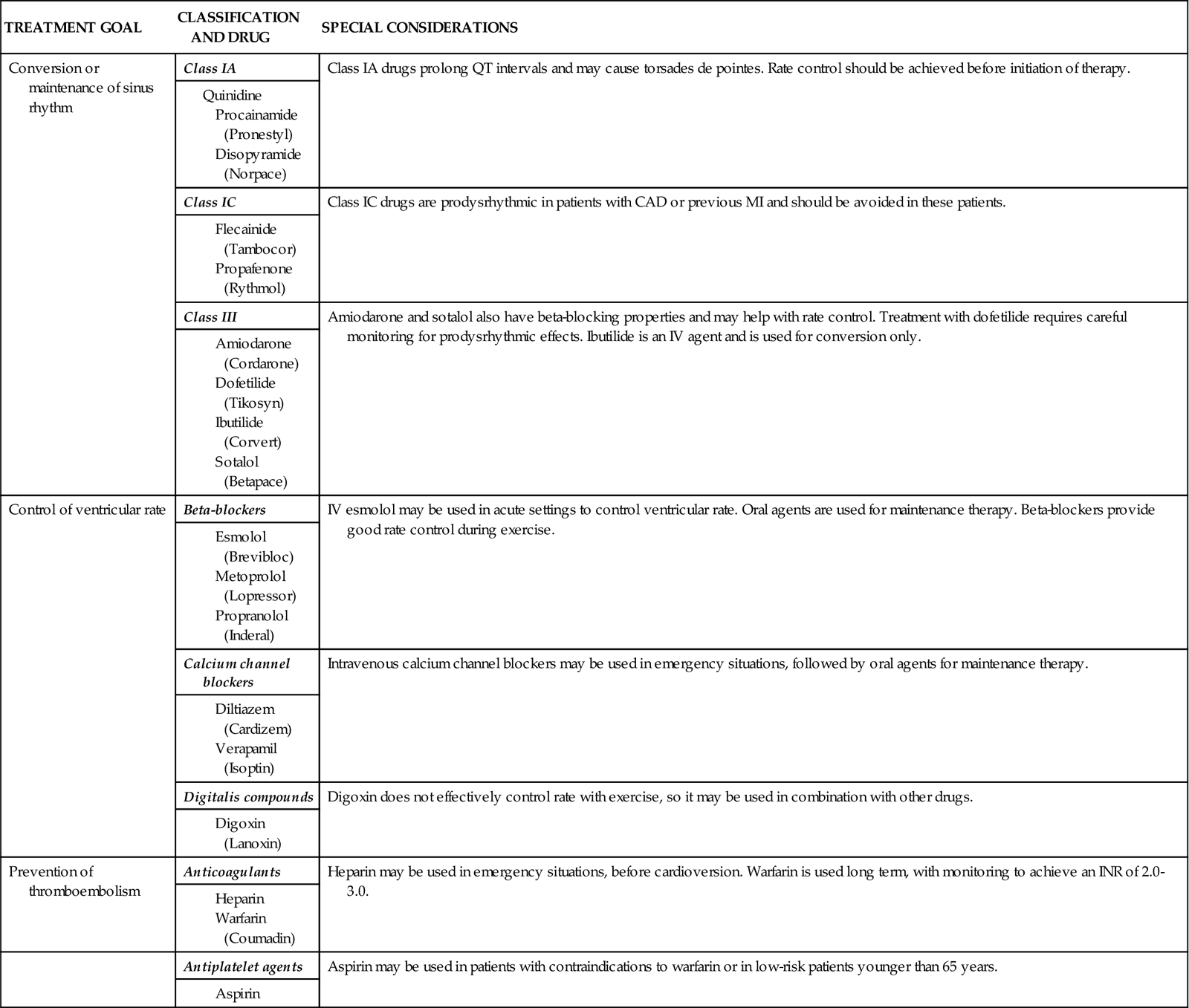
Inotropic Drugs
Critically ill patients with compromised cardiac function often require the use of medications to enhance myocardial contractility (positive inotropes). Clinically available inotropes include cardiac glycosides, sympathomimetics, and phosphodiesterase inhibitors. These agents increase myocardial contractility, resulting in improved cardiac output, more complete emptying of the ventricles, and decreased filling pressures.
Cardiac Glycosides
Cardiac glycosides include digitalis and its derivatives. Although these drugs have been used for centuries, their slow onset of action and risk of toxicity make them more appropriate for management of chronic heart failure. Because digoxin also causes slowing of the sinus rate and a decrease in AV conduction, it may be administered intravenously in the acute care setting to control supraventricular dysrhythmias.
Sympathomimetic Agents
Sympathomimetic agents stimulate adrenergic receptors, thereby simulating the effects of sympathetic nerve stimulation. Included in this category are naturally occurring catecholamines (epinephrine, dopamine, and norepinephrine) and synthetic catecholamines (dobutamine and isoproterenol). The cardiovascular effects of these drugs, which vary according to their selectivity for specific receptor sites, are often dose dependent as well. Table 13-16 describes the cardiovascular effects of sympathomimetic drugs at various dosages.
TABLE 13-16
PHYSIOLOGICAL EFFECTS OF SYMPATHOMIMETIC AGENTS
| RECEPTOR ACTIVATED* | CARDIOVASCULAR EFFECTS | |||||||
| DRUG | DOSAGE | ALPHA | BETA1 | BETA2 | DOPA | CO | HR | SVR |
| Dobutamine | <5 mcg/kg/min | 0 | ↑↑ | ↑ | 0 | ↑↑ | ↑ | ↓ |
| 5-20 mcg/kg/min | 0 | ↑↑↑ | ↑↑ | 0 | ↑↑↑ | ↑↑ | ↓↓ | |
| Dopamine | <3 mcg/kg/min | 0 | ↑ | ↑ | ↑↑↑ | 0/↑ | 0/↑ | 0 |
| 3-10 mcg/kg/min | ↑↑ | ↑↑↑ | ↑ | ↑↑↑ | ↑↑↑ | ↑ | ↑ | |
| 11-20 mcg/kg/min | ↑↑↑ | ↑↑↑ | ↑ | ↑↑ | ↑↑ | ↑↑ | ↑↑↑ | |
| Epinephrine | <2 mcg/min | 0 | ↑ | ↑↑ | 0 | 0/↑ | 0/↑ | ↓ |
| 2-8 mcg/min | ↑↑ | ↑↑↑ | ↑↑ | 0 | ↑↑↑ | ↑↑ | ↑ | |
| 9-20 mcg/min | ↑↑↑ | ↑↑↑ | ↑↑ | 0 | ↑↑ | ↑↑ | ↑↑↑ | |
| Isoproterenol | 1-7 mcg/min | 0 | ↑↑↑ | ↑↑↑ | 0 | ↑↑↑ | ↑↑↑ | ↓↓↓ |
| Norepinephrine | <2 mcg/min | ↑↑↑ | ↑↑ | 0 | 0 | ↑ | 0/↑ | ↑↑↑ |
| 2-16 mcg/min | ↑↑↑↑ | ↑↑ | 0 | 0 | ↓ | ↑ | ↑↑↑↑ | |
| Phenylephrine | 10-100 mcg/min | ↑↑↑↑ | 0 | 0 | 0 | 0 | ↓ | ↑↑↑ |

*See Table 13-13 for actions of receptors.
Dopamine
Dopamine (Intropin) is one of the most widely used drugs in the critical care setting. It is a chemical precursor of norepinephrine, which, in addition to both α- and β-receptor stimulation, can activate dopaminergic receptors in the renal and mesenteric blood vessels. The actions of this drug are entirely dose related.84 At low dosages of 1 to 2 mcg/kg/min, dopamine stimulates dopaminergic receptors, causing vasodilation of the renal and mesenteric vascular beds. The resultant increase in kidney perfusion increases urinary output. However, it is clear that this increase in urine output does not confer protection against the development of acute kidney injury. Moderate dosages result in stimulation of β1-receptors to increase myocardial contractility and improve cardiac output. At dosages greater than 10 mcg/kg/min, dopamine predominantly stimulates α-receptors, resulting in vasoconstriction that often negates both the β-adrenergic and the dopaminergic effects. (Priority Medications box on Dopamine.)
 Priority Medications
Dopamine
Drug Class: Catecholamine/Inotrope
| DRUG ACTION | DRUG DOSAGE AND DRUG DELIVERY |
| Increase urine output | low dose: ≤ 3 mcg/kg/min, IV infusion |
| Increase cardiac output | moderate dose: 3-5 mcg/kg/min, IV infusion |
| Increase blood pressure | high dose: 10-20 mcg/kg/min, IV infusion |
Priority Nursing Considerations
The actions of dopamine are strongly dose related (see above).
Side Effects and Clinical Assessment
Low-dose dopamine to increase urine output: Few systemic side effects expected, although sinus tachycardia. PACs and PVCs occur in some patients. Assess adequacy of urine output.
Moderate-dose dopamine to increase cardiac output: Few systemic side effects expected, although dysrhythmias may occur. Assess cardiac output, BP, peripheral pulses, and color of extremities to avoid any evidence of peripheral vasoconstriction.
High-dose dopamine to treat shock: High-dose dopamine activates peripheral vascular alpha-receptors to cause vasoconstriction with the intent of raising blood pressure in shock states. As with other vasopressors, dopamine should never be administered to a hypovolemic patient, because the resulting vasoconstriction may increase tissue and organ ischemia. The Surviving Sepsis campaign recommends either dopamine or norepinephrine through a central venous catheter (CVC) as a first-line vasopressor to treat shock states following appropriate volume resuscitation. In a study that compared dopamine with norepinephrine to treat shock, patient mortality was identical, but dysrhythmias occurred more frequently in the dopamine group including: sinus tachycardia, atrial fibrillation, PVCs, and ventricular tachycardia.1,2
Always palpate peripheral pulses and check peripheral capillary refill to verify that peripheral circulation is not compromised by the dopamine infusion.
Extravasation Risk & Antidote: Dopamine should not be administered via peripheral IV. The reason is that should the IV infiltrate and dopamine extravasate into the surrounding soft tissues, necrosis can occur.
If extravasation occurs, stop the dopamine infusion. The antidote is phentolamine (an alpha-receptor blocker). Phentolamine 5 to 10 mg is diluted in 10 mL normal saline and administered intradermally into the affected tissues as soon as possible.
Dopamine should be administered via a central venous catheter to avoid this complication.
Clinical Examples
Dopamine is a versatile drug that is used in a variety of clinical situations in critical care. In shock states, high-dose dopamine can be used to maintain blood pressure in combination with volume resuscitation. For the patient with heart failure or following cardiac surgery, dopamine at moderate dose is frequently used to support cardiac output. The aim is to increase cardiac contractility by stimulating the beta-adrenergic receptors in the myocardium. Dopamine is also infused at low dose to increase urine output.
The specificity of the dose-related effects requires the nurse to carefully monitor for both expected and untoward changes in cardiac output, blood pressure, dysrhythmias, urine output and peripheral perfusion.
Dobutamine
Dobutamine (Dobutrex) is a synthetic catecholamine with predominantly β1-adrenergic effects. It also produces some β2 stimulation, resulting in a mild vasodilation. Dobutamine is as effective as dopamine in increasing myocardial contractility and is useful in the treatment of heart failure, especially in hypotensive patients who cannot tolerate vasodilator therapy. The usual dosage range is 2.5 to 20 mcg/kg/min, titrated on the basis of hemodynamic parameters.
Epinephrine
Epinephrine (Adrenalin) is produced by the adrenal gland as part of the body’s response to stress. This agent has the ability to stimulate both α- and β-receptors, depending on the dose administered (see Table 13-14). At doses of 1 to 2 mg/min, epinephrine binds with β-receptors to increase heart rate, cardiac conduction, contractility, and vasodilation, thereby increasing cardiac output. As the dosage is increased, α-receptors are stimulated, resulting in increased vascular resistance and increased blood pressure. At these doses, epinephrine’s impact on cardiac output depends on the heart’s ability to pump against the increased afterload. Epinephrine accelerates the sinus rate and may precipitate ventricular dysrhythmias in the ischemic heart. Other side effects include restlessness, angina, and headache.
Norepinephrine
Norepinephrine (Levophed) is similar to epinephrine in its ability to stimulate β- and α-receptors, but it lacks the β2 effects of epinephrine. At low infusion rates, β1-receptors are activated to produce increased contractility, augmenting cardiac output. At higher doses, the inotropic effects are limited by marked vasoconstriction mediated by α-receptors. Clinically, norepinephrine is used most often as a vasopressor to elevate blood pressure in shock states.
Phosphodiesterase Inhibitors
Phosphodiesterase inhibitors are inotropic agents that also are potent vasodilators (inodilators). Drugs in this classification inhibit the enzyme phosphodiesterase, resulting in increased levels of cyclic adenosine monophosphate (AMP) and intracellular calcium. Amrinone (Inocor) and milrinone (Primacor) were the first of these agents approved for use in the United States. Increases in cardiac output occur as a result of increased contractility (inotropic effects) and decreased afterload (vasodilative effects). Filling pressures tend to decrease, while heart rate and blood pressure remain fairly constant. Amrinone may cause thrombocytopenia, so platelet counts are monitored and patients are observed for hemorrhagic complications. Milrinone is associated with a lower rate of thrombocytopenia but can induce ventricular dysrhythmias (PVCs, VT) in a significant number of patients.85
Vasodilator Drugs
Vasodilators are pharmacological agents that improve cardiac performance by various degrees of arterial or venous dilation, or both. The goal of vasodilator therapy may be reduction of preload or of afterload, or both. Afterload reduction is accomplished by vasodilation of arterial vessels. This results in decreased resistance to LV ejection and may improve cardiac output without increasing myocardial oxygen demands. Reduction of preload is accomplished by dilation of venous vessels to increase capacitance. This results in decreased filling pressures for a failing heart. These drugs may be classified into four groups on the basis of mechanism of action (Table 13-17).
TABLE 13-17
PHARMACOLOGICAL MANAGEMENT: CHARACTERISTICS OF SELECTED VASODILATORS
| CLASSIFICATION AND DRUGS | DOSAGE | PRELOAD | AFTERLOAD | SIDE EFFECTS |
| Direct Smooth Muscle Relaxants | ||||
| Sodium nitroprusside (Nipride) | 0.25-6 mcg/kg/min IV infusion | Moderate | Strong | Hypotension, thiocyanate toxicity, reflex tachycardia |
| Nitroglycerin (Tridil) | 5-300 mcg/min IV infusion | Strong | Mild | Headache, reflex tachycardia, hypotension |
| Calcium Channel Blockers | ||||
| Nicardipine (Cardene) | 5 mg/hr IV, titrated to 15 mg/hr | None | Strong | Hypotension, headache, reflex tachycardia |
| Nifedipine (Procardia) | 10-30 mg PO | None | Strong | Hypotension, headache, reflex tachycardia |
| Angiotensin-Converting Enzyme Inhibitors | ||||
| Captopril (Capoten) | 6.25-100 mg PO every 8-12 hr | Moderate | Moderate | Hypotension, chronic cough, neutropenia |
| Enalapril (Vasotec) | 0.625 mg IV over 5 minutes, then every 6 hours | Moderate | Moderate | Hypotension, elevation of liver enzymes |
| α-Adrenergic Blockers | ||||
| Labetalol (Normodyne) | 20-80 mg IV bolus every 10 minutes, then 1-2 mg/min infusion | Moderate | Moderate | Orthostatic hypotension, bronchospasm, AV block |
| Phentolamine (Regitine) | 1-5 mg IV slowly every 6 hours | Moderate | Moderate | Hypotension, tachycardia |

Direct Smooth Muscle Relaxants
Direct-acting vasodilators include sodium nitroprusside, nitroglycerin, and hydralazine. These drugs produce relaxation of vascular smooth muscle through the activation of nitric oxide, which results in decreased systemic vascular resistance (SVR). Hypotension may occur as a result of peripheral vasodilation, and headaches may be caused by cerebral vasodilation. Compensatory mechanisms can occur in response to the drop in blood pressure. These include baroreceptor activation that causes reflex tachycardia and activation of the renin-angiotensin-aldosterone system (RAAS) (see Figure 12-14 in Chapter 12), with resultant sodium and water retention.
Sodium Nitroprusside
Sodium nitroprusside (Nipride) is a potent, rapidly acting venous and arterial vasodilator that is particularly suitable for rapid reduction of blood pressure in hypertensive emergencies and perioperatively. It also is effective for afterload reduction in the setting of severe heart failure. The drug is administered by continuous intravenous infusion, with the dosage titrated to maintain the desired blood pressure and SVR. Prolonged administration can result in thiocyanate toxicity, manifested by nausea, confusion, and tinnitus.86
Nitroglycerin
Intravenous nitroglycerin (Tridil) causes both arterial and venous vasodilation, but its venous effect is more pronounced. It is used in the critical care setting for the treatment of acute heart failure because it reduces cardiac filling pressures, relieves pulmonary congestion, and decreases cardiac workload and oxygen consumption. Nitroglycerin dilates the coronary arteries and is a useful adjunct in the treatment of unstable angina and acute MI. The initial dosage is 10 mcg/min, and the infusion is titrated upward to achieve the desired clinical effect: a reduction or elimination of chest pain, decreased PAOP (wedge pressure), or a decrease in blood pressure. Nitroglycerin is administered prophylactically to prevent coronary vasospasm after coronary angioplasty, atherectomy, stent insertion, or fibrinolytic therapy. The most common side effects of this drug are hypotension, flushing, and headache.85
Calcium Channel Blockers
Calcium channel blockers are a chemically diverse group of drugs with differing pharmacological effects (Table 13-18).
TABLE 13-18
PHARMACOLOGICAL MANAGEMENT: CHARACTERISTICS OF CALCIUM CHANNEL BLOCKERS
| DRUG | ACTIONS | DOSAGE | SPECIAL CONSIDERATIONS |
| Dihydropyridines | |||
| Nicardipine (Cardene) | Short-term control of hypertension | 5 mg/hr IV, titrated to 15 mg/hr | Hypotension, headache, nausea |
| Nifedipine (Procardia) | Hypertension | 10-30 mg PO | Hypotension, headache, reflex tachycardia |
| Benzothiazepines | |||
| Diltiazem (Cardizem) | SVT, AFib, AF, angina | Bolus dose of 0.25 mg/kg IV over 2 minutes, followed by an infusion of 5-15 mg/hr | Bradycardia, hypotension, atrioventricular block |
| Phenylalkylamines | |||
| Verapamil (Calan, Isoptin) | AF, PSVT | 5-10 mg IV, may repeat in 15-30 minutes | Hypotension, bradycardia, heart failure |
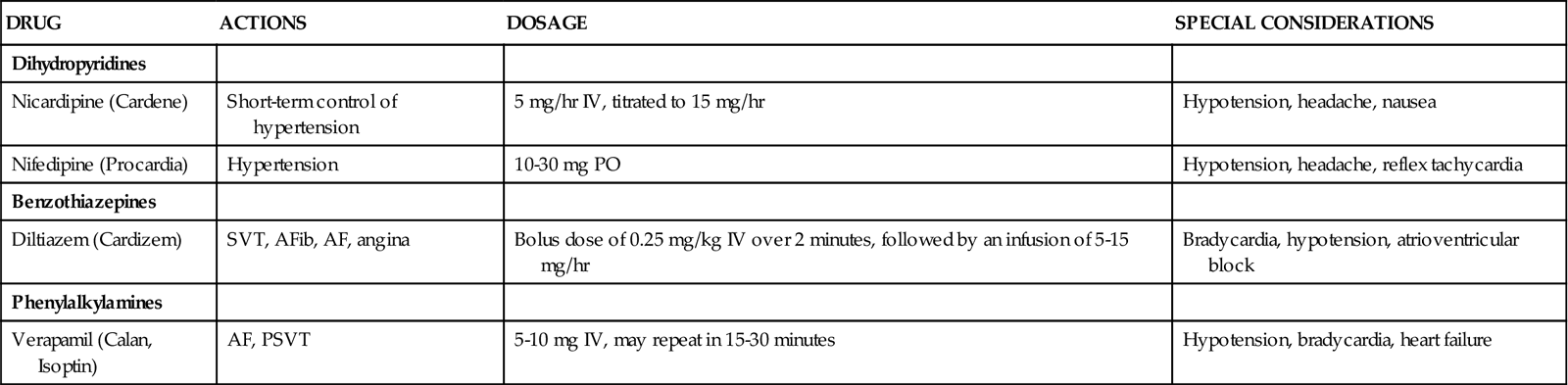
Nifedipine (Procardia) and nicardipine (Cardene) are dihydropyridines. Drugs in this group of calcium channel blockers (with the suffix pine) are used primarily as arterial vasodilators. These agents reduce the influx of calcium in the arterial resistance vessels. Both coronary and peripheral arteries are affected. They are used in the critical care setting to treat hypertension. Nifedipine is available only in an oral form, but in the past it was prescribed sublingually during hypertensive emergencies. Reports of adverse events associated with sublingual nifedipine have prompted the FDA to strongly discourage sublingual use.87 Nicardipine has become available as an intravenous calcium channel blocker, and it offers more accurate titration for effective control of hypertension. Side effects of nifedipine and nicardipine are related to vasodilation and include hypotension, reflex tachycardia, flushing, headache, and ankle edema.
Diltiazem (Cardizem) is from the benzothiazepine group of calcium channel blockers. Verapamil (Calan, Isoptin) is part of the phenylalkylamine group. The different classifications account for the differing actions of these calcium channel blockers. These drugs dilate coronary arteries but have little effect on the peripheral vasculature. They are used in the treatment of angina, especially that which has a vasospastic component, and as antidysrhythmics in the treatment of supraventricular tachycardias.
Angiotensin-Converting Enzyme Inhibitors
Angiotensin-converting enzyme (ACE) inhibitors produce vasodilation by blocking the conversion of angiotensin I to angiotensin II. Because angiotensin is a potent vasoconstrictor, limiting its production decreases SVR. In contrast to the direct vasodilators and nifedipine, ACE inhibitors do not cause reflex tachycardia or induce sodium and water retention. However, these drugs may cause a profound fall in blood pressure, especially in patients who are volume-depleted. Blood pressure must be monitored carefully, especially at the initiation of therapy.
Captopril (Capoten) and enalapril (Vasotec) are used in patients with heart failure to decrease SVR (afterload) and PAOP (preload). Captopril is available only in an oral form, but it has a relatively rapid onset of action (approximately 1 hour). Enalapril is available in an intravenous form and may be used to decrease afterload in more emergent situations.
Atrial Natriuretic Peptide
Nesiritide (Natrecor) is a new vasodilator used in the treatment of acute heart failure. This agent is a recombinant form of human brain natriuretic peptide (BNP), the hormone released by cardiac cells in response to ventricular distention. The primary effects of nesiritide include decreased filling pressures (PAOP, CVP), reduced SVR, and increased urine output. Compared with traditional vasodilator therapy for acute heart failure, nesiritide reportedly is as effective as the traditional agents and has fewer side effects (e.g., headache).85 The recommended dose is an intravenous bolus of 2 mcg/kg, followed by a continuous infusion of 0.01 mcg/kg/min. The primary side effect is hypotension. If this occurs, nesiritide may need to be discontinued for a time and then restarted at a lower dose after the patient has stabilized.85 Low-dose nesiritide may have a protective effect on kidney function.88 High dose administration is associated with hypotension and dysrythmias.88
Alpha-Adrenergic Blockers
Peripheral adrenergic blockers block α-receptors in arteries and veins, resulting in vasodilation. Orthostatic hypotension is a common side effect and may result in syncope. Long-term therapy also may be complicated by fluid and water retention.
Labetalol (Normodyne), a combined peripheral alpha-blocker and cardioselective beta-blocker, is used in the treatment of acute stroke and hypertensive emergencies.89 Because the blockade of β1-receptors permits the decrease of blood pressure without the risk of reflexive tachycardia and increased cardiac output, this drug is also useful in the treatment of acute aortic dissection.90
Phentolamine (Regitine) is a nonselective peripheral alpha-blocker that decreases blood pressure through arterial vasodilation. The half-life is 19 minutes when given intravenously. It is administered by slow IV push, 1 to 5 mg every 6 hours to reduce blood pressure.86 This drug is used only in very specific circumstances. Phentolamine is the drug of choice to control blood pressure and sweating caused by pheochromocytoma, an epinephrine (adrenaline)-secreting tumor that can arise from the adrenal medulla.86
Phentolamine also is used to treat the extravasation of dopamine or other vasopressors into peripheral tissues. If this occurs, 5 to 10 mg is diluted in 10 mL normal saline and administered intradermally into the infiltrated area as soon as possible following the extravasation.
Dopamine Receptor Agonists
Fenoldopam (Corlopam) is the first of a new class of vasodilators called selective, specific dopamine (D1) receptor agonists.86 The drug is a potent vasodilator that affects peripheral, renal, and mesenteric arteries. It is administered by continuous intravenous infusion beginning at 0.1 mcg/kg/min and titrated up to the desired blood pressure effect, with a maximum recommended dose of 1.6 mcg/kg/min. It can be administered as an alternative to sodium nitroprusside or other antihypertensives in the treatment of hypertensive emergencies. Fenoldopam can be used safely in patients with kidney dysfunction.86
Vasopressors
Vasopressors are sympathomimetic agents that mediate peripheral vasoconstriction through stimulation of α-receptors (see Table 13-16). This results in increased SVR and elevates blood pressure. Some of these drugs (epinephrine and norepinephrine) also have the ability to stimulate β-receptors. Vasopressors are not widely used in the treatment of critically ill cardiac patients, because the dramatic increase in afterload is taxing to a damaged heart. Vasopressors are also used to maintain organ perfusion in shock states. For example, norepinephrine (Levophed) may be administered as a continuous intravenous infusion to maintain organ perfusion by increasing SVR in cases of severe sepsis or septic shock.
Vasopressin
Vasopressin, also known as antidiuretic hormone (ADH), has become popular in the critical care setting for its vasoconstrictive effects. At higher doses, vasopressin directly stimulates V1 receptors in vascular smooth muscle, resulting in vasoconstriction of capillaries and small arterioles. A one-time dose of 40 units intravenously is recommended in the ACLS guidelines as first-line drug therapy for VF, pulseless VT asystole, or pulseless electrical activity (PEA).91 Continuous infusions of 0.02 unit/min up to 0.1 unit/min have been used in the treatment of vasodilatory shock in patients with refractory hypotension after cardiopulmonary bypass.62
In septic shock, vasopressin levels have been reported to be lower than anticipated for a shock state.92 Vasopressin continuous infusion of 0.03 unit/min may be added to the norepinephrine infusion in refractory shock per the 2008 surviving sepsis guidelines.92 Patients must be assessed for side effects such as heart failure caused by the antidiuretic effects, and monitored for increased risk of ischemia in the myocardium, spleen, and periphery.92 Vasopressin should be infused through a central line to avoid the risk of peripheral extravasation and resultant tissue necrosis. Placement of an arterial line in shock states to monitor blood pressure and SVR is recommended.92
Drug Treatment of Heart Failure
Almost 5 million Americans have heart failure, making it a major chronic health issue.93 The goals of treatment in heart failure include alleviating symptoms, slowing the progression of the disease, and improving survival. Findings from a number of randomly controlled clinical trials have resulted in guidelines for the pharmacological treatment of heart failure.94,95 Please see the Concept Map on Heart Failure, which integrates pharmacological management of heart failure. Additional information about heart failure is available in Chapter 12. Table 13-19 reviews the drugs currently recommended for the treatment of heart failure.
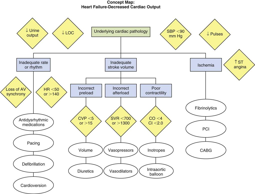
TABLE 13-19
PHARMACOLOGICAL MANAGEMENT: HEART FAILURE