Breathing systems
Breathing systems must fulfil three objectives:
2. Removal of carbon dioxide from the patient.
3. Delivery of inhaled anaesthetic agents. These agents are predominantly eliminated by the lungs also, so the breathing system must be able to expel them as necessary.
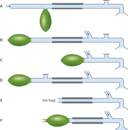
There are several breathing systems used in anaesthesia. Mapleson classified them into A, B, C, D and E. After further revision of the classification, a Mapleson F breathing system was added (Fig. 4.1). Currently, only systems A, D, E and F and their modifications are commonly used during anaesthesia. Mapleson B and C systems are used more frequently during the recovery period and in emergency situations.
Properties of the ideal breathing system
2. Delivers the intended inspired gas mixture.
3. Permits spontaneous, manual and controlled ventilation in all age groups.
4. Efficient, requiring low FGF rates.
5. Protects the patient from barotrauma.
6. Sturdy, compact and lightweight in design.
Components of the breathing systems
Adjustable pressure limiting (APL) valve
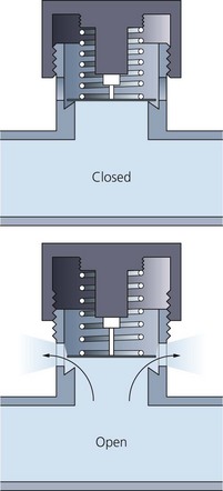
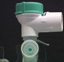
This is a valve which allows the exhaled gases and excess FGF to leave the breathing system (Fig. 4.2). It does not allow room air to enter the breathing system. Synonymous terms for the APL valve are expiratory valve, spill valve and relief valve.
Components
1. Three ports: the inlet, the patient and the exhaust ports. The latter can be open to the atmosphere or connected to the scavenging system using a shroud.
2. A lightweight disc rests on a knife-edge seating. The disc is held onto its seating by a spring. The tension in the spring, and therefore the valve’s opening pressure, are controlled by the valve dial.
Mechanism of action
1. This is a one-way, adjustable, spring-loaded valve. The spring is used to adjust the pressure required to open the valve. The disc rests on a knife-edge seating in order to minimize its area of contact.
2. The valve allows gases to escape when the pressure in the breathing system exceeds the valve’s opening pressure.
3. During spontaneous ventilation, the patient generates a positive pressure in the system during expiration, causing the valve to open. A pressure of less than 1 cm H2O (0.1 kPa) is needed to actuate the valve when it is in the open position.
4. During positive pressure ventilation, a controlled leak is produced by adjusting the valve dial during inspiration. This allows control of the patient’s airway pressure.
Problems in practice and safety features
1. Malfunction of the scavenging system may cause excessive negative pressure. This can lead to the APL valve remaining open throughout respiration. This leads to an unwanted enormous increase in the breathing system’s dead space.
2. The patient may be exposed to excessive positive pressure if the valve is closed during assisted ventilation. A pressure relief safety mechanism actuated at a pressure of about 60 cm H2O is present in some designs (Fig. 4.3).
3. Water vapour in exhaled gas may condense on the valve. The surface tension of the condensed water may cause the valve to stick. The disc is usually made of a hydrophobic (water repelling) material, which prevents water condensing on the disc.
Reservoir bag
The reservoir bag is an important component of most breathing systems.
Components
1. It is made of anti-static rubber or plastic. Latex-free versions also exist. Designs tend to be ellipsoidal in shape.
2. The standard adult size is 2 L. The smallest size for paediatric use is 0.5 L. Volumes from 0.5 to 6 L exist. Bigger size reservoir bags are useful during inhalational induction, e.g. adult induction with sevoflurane.
Mechanism of action
1. Accommodates the FGF during expiration acting as a reservoir available for the following inspiration. Otherwise, the FGF must be at least the patient’s peak inspiratory flow to prevent rebreathing. As this peak inspiratory flow may exceed 30 L/min in adults, breathing directly from the FGF will be insufficient.
2. It acts as a monitor of the patient’s ventilatory pattern during spontaneous breathing. It serves as a very inaccurate guide to the patient’s tidal volume.
3. It can be used to assist or control ventilation.
4. When employed in conjunction with the T-piece (Mapleson F), a 0.5 L double-ended bag is used. The distal hole acts as an expiratory port (Fig. 4.4).
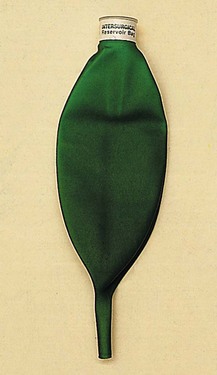
Fig. 4.4 A 0.5-L double-ended reservoir.
Problems in practice and safety features
1. Because of its compliance, the reservoir bag can accommodate rises in pressure in the breathing system better than other parts. When grossly overinflated, the rubber reservoir bag can limit the pressure in the breathing system to about 40 cm H2O. This is due to the law of Laplace dictating that the pressure (P) will fall as the bag’s radius (r) increases: P = 2(tension)/r.
2. The size of the bag depends on the breathing system and the patient. A small bag may not be large enough to provide a sufficient reservoir for a large tidal volume.
3. Too large a reservoir bag makes it difficult for it to act as a respiratory monitor.
Magill system (Mapleson A)
This breathing system is popular and widely used in the UK.
Mechanism of action
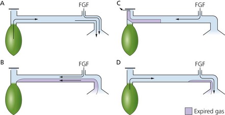
1. During the first inspiration, all the gases are fresh and consist of oxygen and anaesthetic gases from the anaesthetic machine.
2. As the patient exhales (Fig. 4.5C), the gases coming from the anatomical dead space (i.e. they have not undergone gas exchange so contain no CO2) are exhaled first and enter the tubing and are channelled back towards the reservoir bag which is being filled continuously with FGF.
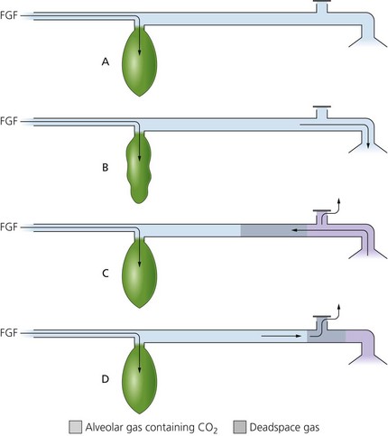
3. During the expiratory pause, pressure built up within the system allows the FGF to expell the alveolar gases first out through the APL valve (Fig. 4.5D).
4. By that time the patient inspires again (Fig. 4.5B), getting a mixture of FGF and the rebreathed anatomical dead space gases.
5. It is a very efficient system for spontaneous breathing. Because there is no gas exchange in the anatomical dead space, the FGF requirements to prevent rebreathing of alveolar gases are theoretically equal to the patient’s alveolar minute volume (about 70 mL/kg/min).
6. The Magill system is not an efficient system for controlled ventilation. A FGF rate of three times the alveolar minute volume is required to prevent rebreathing.
Lack system (Mapleson A)
This is a coaxial modification of the Magill Mapleson A system.
Components
1. 1.8 m length coaxial tubing (tube inside a tube). The FGF is through the outside tube, and the exhaled gases flow through the inside tube (Fig. 4.6A).
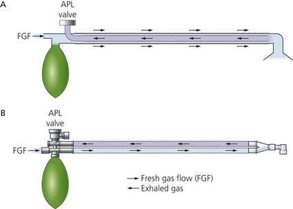
2. The inside tube is wide in diameter (14 mm) to reduce resistance to expiration. The outer tube’s diameter is 30 mm.
3. The reservoir bag is mounted at the machine end.
4. The APL valve is mounted at the machine end eliminating the drag on the connections at the patient end, which is a problem with the Magill system.
Mechanism of action
1. A similar mechanism to the Magill system except the Lack system is a coaxial version. The fresh gas flows through the outside tube whereas the exhaled gases flow through the inside tube.
2. A FGF rate of about 70 mL/kg/min is required in order to prevent rebreathing. This makes it an efficient breathing system for spontaneous ventilation.
3. Since it is based on the Magill system, it is not suitable for controlled ventilation.
Instead of the coaxial design, a parallel tubing version of the system exists (Fig. 4.6B). This has separate inspiratory and expiratory tubing, and retains the same flow characteristics as the coaxial version.
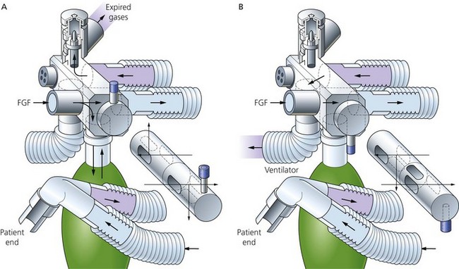
Bain system (Mapleson D)
The Bain system is a coaxial version of the Mapleson D system (Fig. 4.7). It is lightweight and compact at the patient end. It is useful where access to the patient is limited, such as during head and neck surgery.
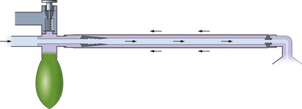
Fig. 4.7 The Bain breathing system.
Components
1. A length of coaxial tubing (tube inside a tube). The usual length is 180 cm, but it can be supplied at 270 cm (for dental or ophthalmic surgery) and 540 cm (for magnetic resonance imaging (MRI) scans where the anaesthetic machine needs to be kept outside the scanner’s magnetic field). Increasing the length of the tubing does not affect the physical properties of the breathing system.
2. The fresh gas flows through the inner tube while the exhaled gases flow through the outside tube (Fig. 4.8). The internal lumen has a swivel mount at the patient end. This ensures that the internal tube cannot kink, so ensuring delivery of fresh gas to the patient.
Mechanism of action
1. During spontaneous ventilation, the patient’s exhaled gases are channelled back to the reservoir bag and become mixed with fresh gas (Fig. 4.9B). Pressure build-up within the system will open the APL valve allowing the venting of the mixture of the exhaled gases and fresh gas (Fig. 4.9C).
2. The FGF required to prevent rebreathing (as seen in Fig. 4.9D) during spontaneous ventilation is about 1.5–2 times the alveolar minute volume. A flow rate of 150–200 mL/kg/min is required. This makes it an inefficient and uneconomical system for use during spontaneous ventilation.
3. It is a more efficient system for controlled ventilation. A flow of 70–100 mL/kg/min will maintain normocapnia. A flow of 100 mL/kg/min will cause moderate hypocapnia during controlled ventilation.
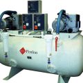
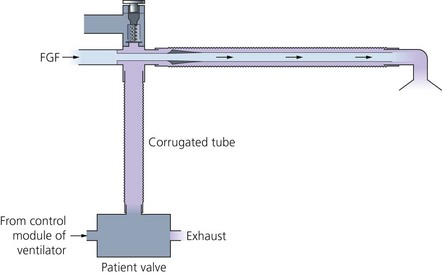
4. Connection to a ventilator is possible (Fig. 4.10). By removing the reservoir bag, a ventilator such as the Penlon Nuffield 200 can be connected to the bag mount using a 1-m length of corrugated tubing (the volume of tubing must exceed 500 mL if the driving gas from the ventilator is not to enter the breathing system). The APL valve must be fully closed.
Problems in practice and safety features
1. The internal tube can kink, preventing fresh gas being delivered to the patient.
2. The internal tube can become disconnected at the machine end causing a large increase in the dead space, resulting in hypoxaemia and hypercapnia. Movement of the reservoir bag during spontaneous ventilation is not therefore an indication that the fresh gas is being delivered to the patient.
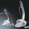
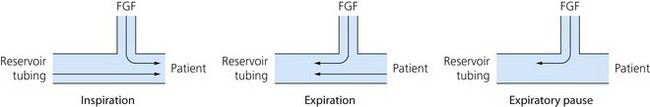
T-piece system (Mapleson E and F)
This is a valveless breathing system used in anaesthesia for children up to 25–30 kg body weight (Fig. 4.11). It is suitable for both spontaneous and controlled ventilation.
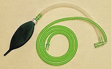
Fig. 4.11 A T-piece breathing system.
Components
1. A T-shaped tubing with three open ports (Fig. 4.12).
2. Fresh gas from the anaesthetic machine is delivered via a tube to one port.
3. The second port leads to the patient’s mask or tracheal tube. The connection should be as short as possible to reduce dead space.
4. The third port leads to reservoir tubing. Jackson-Rees added a double-ended bag to the end of the reservoir tubing (making it Mapleson F).
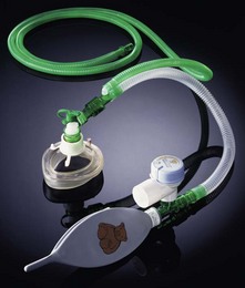
5. A recent modification exists where an APL valve is included before a closed-ended 500 mL reservoir bag. A pressure relief safety mechanism in the APL valve is actuated at a pressure of 30 cm H2O (Fig. 4.13). This design allows effective scavenging.
Mechanism of action
1. The system requires an FGF of 2.5–3 times the minute volume to prevent rebreathing with a minimal flow of 4 L/min.
2. The double-ended bag acts as a visual monitor during spontaneous ventilation. In addition, the bag can be used for assisted or controlled ventilation.
3. The bag can provide a degree of continuous positive airway pressure (CPAP) during spontaneous ventilation.
4. Controlled ventilation is performed either by manual squeezing of the double-ended bag (intermittent occlusion of the reservoir tubing in the Mapleson E) or by removing the bag and connecting the reservoir tubing to a ventilator such as the Penlon Nuffield 200.
5. The volume of the reservoir tubing determines the degree of rebreathing (too large a tube) or entrainment of ambient air (too small a tube). The volume of the reservoir tubing should approximate to the patient’s tidal volume.
Problems in practice and safety features
1. Since there is no APL valve used in this breathing system, scavenging is a problem.
2. Patients under 6 years of age have a low functional residual capacity (FRC). Mapleson E was designed before the advantages of CPAP were recognized for increasing the FRC. This problem can be partially overcome in the Mapleson F with the addition of the double-ended bag.
The Humphrey ADE breathing system
This is a very versatile breathing system which combines the advantages of Mapleson A, D and E systems. It can therefore be used efficiently for spontaneous and controlled ventilation in both adults and children. The mode of use is determined by the position of one lever which is mounted on the Humphrey block (Fig. 4.14). Both parallel and coaxial versions exist with similar efficiency. The parallel version will be considered here.
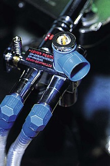
Components
1. Two lengths of 15 mm smooth-bore tubing (corrugated tubing is not recommended). One delivers the fresh gas and the other carries away the exhaled gas. Distally they are connected to a Y-connection leading to the patient. Proximally they are connected to the Humphrey block.
2. The Humphrey block is at the machine end and consists of:
Mechanism of action
1. With the lever up (Fig. 4.15A) in the spontaneous mode, the reservoir bag and APL valve are connected to the breathing system as in the Magill system.
2. With the lever down (Fig. 4.15B) in the ventilator mode, the reservoir bag and the APL valve are isolated from the breathing system as in the Mapleson E system. The expiratory tubing channels the exhaled gas via the ventilator port. Scavenging occurs at the ventilator’s expiratory valve.
3. The system is suitable for paediatric and adult use. The tubing is rather narrow, with a low internal volume. Because of its smooth bore, there is no significant increase in resistance to flow compared to the 22-mm corrugated tubing used in other systems. Small tidal volumes are possible during controlled ventilation and less energy is needed to overcome the inertia of gases during spontaneous ventilation.
4. The presence of an APL valve in the breathing system offers a physiological advantage during paediatric anaesthesia, since it is designed to offer a small amount of PEEP (1 cm H2O).
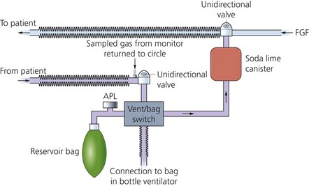
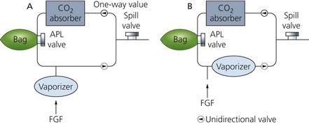
Soda lime and the circle breathing system
In this breathing system, soda lime is used to absorb the patient’s exhaled carbon dioxide (Fig. 4.16). FGF requirements are low, making the circle system very efficient and causing minimal pollution. As a result, there has been renewed interest in low-flow anaesthesia due to the cost of new, expensive inhalational agents, together with the increased awareness of the pollution caused by the inhalational agents themselves (see Table 3.1).
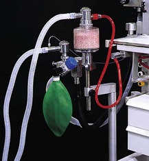
Fig. 4.16 The circle breathing system.
Depending on the FGF, the system can either be:
• Closed circle anaesthesia. The FGF is just sufficient to replace the volume of gas and vapour taken up by the patient. No gas leaves via the APL valve and the exhaled gases are rebreathed after carbon dioxide is absorbed. Significant leaks from the breathing system are eliminated. In practice, this is possible only if the gases sampled by the gas analyser are returned back to the system.
• Minimal flow anaesthesia. The FGF is reduced to 0.5 L/min.
• Low-flow anaesthesia. The FGF used is less than the patient’s alveolar ventilation (usually below 1.5 L/min). Excess gases leave the system via the APL valve.
Components
1. A vertically positioned canister containing soda lime. The canister has two ports, one to deliver inspired gases to the patient and the other to receive exhaled gases from the patient.
2. Inspiratory and expiratory tubings connected to the canister. Each port incorporates a unidirectional valve.
3. FGF from the anaesthetic machine is positioned distal to the soda lime canister, but proximal to the inspiratory valve.
4. An APL valve is positioned between the expiratory valve and canister and connected to a 2-L reservoir bag.
5. A vaporizer mounted on the anaesthetic machine back bar (vaporizer outside circle – VOC) or a vaporizer positioned on the expiratory limb within the system (vaporizer inside circle – VIC).
6. Soda lime consists of 94% calcium hydroxide and 5% sodium hydroxide with a small amount of potassium hydroxide (less than 0.1%). It has a pH of 13.5 and a moisture content of 14–19%. Some modern types of soda lime have no potassium hydroxide. Soda lime granules are prone to powder formation, especially during transport. Disintegrated granules increase resistance to breathing. Because of this, silica (0.2%) is added to harden the absorbents and reduce powder formation. A dye or colour indicator is added to change the granules’ colour when the soda lime is exhausted. Colour changes can be from white to violet/purple (ethyl violet dye), from pink to white (titan yellow dye) or from green to violet. Colour changes occur when the pH is less than 10. Newer types of soda lime have a low concentration of a zeolite added. This helps to maintain the pH at a high level for longer and retains moisture so improving carbon dioxide absorption and reducing the formation of carbon monoxide and compound A.
7. The size of soda lime granules is 4–8 mesh. Strainers with 4–8 mesh have four and eight openings per inch respectively. Therefore, the higher the mesh number, the smaller the particles are. Recently produced soda lime made to a uniform shape of 3–4-mm spheres allows more even flow of gases and a reduction in channelling. This results in a longer life with lower dust content and lower resistance to flow: 1 kg can absorb more than 120 L of CO2.
8. Barylime, which consists of barium hydroxide (80%) and calcium hydroxide (20%), is widely used in the USA. Another absorber is Amsorb® that consists of CaCl2 and Ca(OH)2.
Mechanism of action
1. High FGF of several L/min is needed in the initial period to denitrogenate the circle system and the functional residual capacity (FRC). This is important to avoid the build up of unacceptable levels of nitrogen in the system. In closed circle anaesthesia, a high FGF is needed for up to 15 minutes. In low-flow anaesthesia, a high FGF of up to 6 minutes is required. The FGF can be later reduced to 0.5–1 L/min. If no N2O is used during anaesthesia (i.e. an oxygen/air mix is used), it is not necessary to eliminate nitrogen because air contains nitrogen. A short period of high flow is needed to prime the system and the patient with the inhalational agent.
2. Exhaled gases are circled back to the canister, where carbon dioxide absorption takes place and water and heat (exothermic reaction) are produced. The warmed and humidified gas joins the FGF to be delivered to the patient (Fig. 4.17).
3. Chemical sequences for the absorption of carbon dioxide by soda lime:
a) Note how both NaOH and KOH are regenerated at the expense of Ca(OH)2. This explains soda lime’s mix – only a little Na(OH) and K(OH) and a lot of Ca(OH)2:
b) As can be seen above, this is an exothermic reaction, which alters the pH of the whole system. The reaction also produces water. One mole of water is produced for each mole of CO2 absorbed.
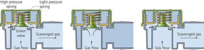
c) The direction of gas flow is controlled via the unidirectional valves made of discs that rest on a ‘knife-edge’ (Fig. 4.18). They allow gas to flow in one direction only and prevent the mixing of inspired and expired gases, thus preventing rebreathing. These are mounted in see-through plastic domes so that they can be seen to be working satisfactorily.
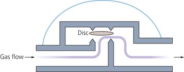
Fig. 4.18 Circle system unidirectional valve.
4. The canister is positioned vertically to prevent exhaled gas channelling through unfilled portions. Larger canisters are more efficient than smaller ones because of the higher litres of CO2/kg weight capacity. Double absorbers with two cartridges used simultaneously are more efficient than single absorbers.
5. The lower the FGF used, the more rapidly soda lime granules are consumed. This is because most of the exhaled gases pass through the absorber with very little being discarded through the APL valve. For a 70–80 kg patient with a tidal volume of 500 mL, respiratory rate of 12/min and CO2 production of 250 mL/min, using an FGF of 1 L/min, the soda lime will be exhausted after 5–7 hours of use. For the same patient but using an FGF of 3 L/min, the soda lime will be exhausted after 6–8 hours of use.
6. The circle system can be used for both spontaneous and controlled ventilation.
7. Disposable circle breathing systems exist. They feature coaxial inspiratory tubing. The inner tubing delivers the FGF from the anaesthetic machine and the outer tubing delivers the recircled gas flow. Both gas flows mix distally. This allows a more rapid change in the inhalational gas and vapour concentration at the patient end.
Use of vaporizers in the circle breathing system
VOC vaporizers (Fig. 4.19) are positioned on the back bar of the anaesthetic machine. They are high-efficiency vaporizers that can deliver high-output concentrations at low flows. They have high internal resistance.
1. The vaporizer should be able to deliver accurate concentrations of inhalational agent with both high and low FGFs. This is easily achieved by most modern vaporizers, e.g. the Tec series.
2. The volume of the circle system is large in relation to the low FGF used. Rapid changes in the concentration of the inspired vapour can be achieved by increasing the FGF to the circle system. Delivering the FGF distally, using a coaxial inspiratory tubing design, allows faster changes in inspired vapour concentration compared to conventional circle systems at low flows.
VIC vaporizers (see Fig. 4.19) are designed to offer minimal resistance to gas flow and have no wicks on which water vapour might condense (e.g. Goldman vaporizer). The VIC is a low-efficiency vaporizer adding only small amounts of vapour to the gas recirculating through it.
1. FGF will be vapour free and thus dilutes the inspired vapour concentration.
2. During spontaneous ventilation, respiration is depressed with deepening of anaesthesia. Uptake of the anaesthetic agent is therefore reduced. This is an example of a feedback safety mechanism. The safety mechanism is lost during controlled ventilation.
Problems in practice and safety features
1. Adequate monitoring of inspired oxygen, end-tidal carbon dioxide and inhalational agent concentrations is essential.
2. The unidirectional valves may stick and fail to close because of water vapour condensation. This leads to an enormous increase in dead space.
3. The resistance to breathing is increased especially during spontaneous ventilation. The main cause of resistance to breathing is due to the unidirectional valves. Dust formation can increase resistance to breathing further. It can also lead to clogging and channelling, so reducing efficiency. Newer soda lime designs claim less dust formation.
4. Compound A (a penta-fluoroisoproprenyl fluoro-methyl ether, which is nephrotoxic in rats) is produced when sevoflurane is used in conjunction with soda lime. This is due to the degradation of sevoflurane (dehydrohalogenation) as a result of the alkali metal hydroxide present in soda lime.
Factors that increase the production of compound A are:
b) high sevoflurane concentrations
c) use of barylime rather than soda lime
e) newer designs of soda lime, being non-caustic (no KOH and only very low levels of NaOH), claim less or no production of compound A. For substance A production, barylime is worse than soda lime and Amsorb® is the safest.
5. Carbon monoxide production can occur when volatile agents containing the CHF2 moiety (enflurane, isoflurane and desflurane) are used with very dry grannules when the water content is less than 1.5% in soda lime or less than 5% in barylime. This can occur when the system is left unused for a long length of time, e.g. overnight or at weekends, or when a small basal flow from the anaesthetic machine occurs. Carbon monoxide accumulation and subsequent carboxyhaemoglobin formation is said to occur at less than 0.1% per hour, so may become significant in smokers when ultra-low flows are used; oxygen flushes of the system (e.g. once an hour) will prevent this.
6. Other substances can accumulate such as methane, acetone, ethanol and hydrogen. However, they do not generally become clinically significant.
7. Uneven filling of the canister with soda lime leads to channelling of gases and decreased efficiency.
8. The circle system is bulkier, less portable and more difficult to clean.
9. Soda lime is corrosive. Protective clothing, gloves and eye/face protection can be used.
10. Because of the many connections, there is an increased potential for leaks and disconnection.
Waters canister (‘to-and-fro’) bidirectional flow breathing system
Currently, this system is not widely used in anaesthetic practice. It consists of a Mapleson C system with a soda lime canister positioned between the APL valve and the reservoir. A filter is positioned in the canister to prevent the soda lime granules ‘entering’ the breathing system and the risk of inhaling them. It is not an efficient system as the granules nearest to the patient are exhausted first, so increasing the dead space. It is also a cumbersome system as the canister has to be positioned horizontally and packed tightly with the soda lime granules to prevent channelling of the gases (Fig. 4.20).
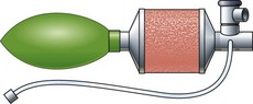
Fig. 4.20 The Waters canister breathing system.
In the following lists, which of the statements (a) to (e) are true?
1. APL valve in a breathing system:
a) In the open position, a pressure of less than 1 cm H2O (0.1 kPa) is needed to actuate the valve.
b) A pressure relief mechanism is activated at a pressure of 60 cm H2O.
c) Is incorporated in the T-piece breathing system.
d) The dead space of the breathing system is reduced during spontaneous ventilation when excessive negative pressure from the scavenging system is applied through the APL valve.
e) Should be closed during controlled ventilation using a Bain breathing system and an intermittent blower ventilator.
a) The FGF rate required to prevent rebreathing of alveolar gas in the breathing system is a measure of the efficiency of a breathing system.
b) The reservoir bag limits the pressure build-up in a breathing system to about 40 cm H2O.
c) A FGF of 150 mL/kg/min is needed in the Mapleson A system during spontaneous ventilation.
d) The inner tube in the Bain system delivers the FGF.
e) The Humphrey ADE system can be used for spontaneous ventilation only.
a) The face mask in the Mapleson A breathing system has no effect on the dead space.
b) Disconnection of the inner tube at the patient’s end in the Bain system results in an increase in dead space.
c) Failure of the unidirectional valves to close in the circle system has no effect on the system’s dead space.
d) The anatomic dead space is about 150 mL.
e) Bohr’s equation is used to measure the physiological dead space.
a) 20% volume for volume of soda lime is sodium hydroxide.
c) 1 kg of soda lime can absorb about 120 mL of CO2.
a) Is an example of a Mapleson A system.
b) Requires a FGF of 70 mL/kg during spontaneous ventilation.
c) Is made of standard corrugated tubing.
d) Can be used in a T-piece system.
e) Can be used for both spontaneous and controlled ventilation.
a) Can be used in paediatric practice only.
b) Mapleson F system is the E system plus an open-ended reservoir bag.
d) With a constant FGF, a too small reservoir has no effect on the performance of the system.
e) The reservoir bag in Mapleson F provides a degree of CPAP during spontaneous ventilation.
7. Which of the following are true and which are false?
a) The Magill classification is used to describe anaesthetic breathing systems.
b) Modern anaesthetic breathing systems are constructed using anti-static materials.
c) Efficiency of a breathing system is determined by the mode of ventilation of the patient.
d) As long as the valve is present in a breathing system, its position is not important.
8. The circle breathing system:
a) With low flow rates, substance A can be produced when sevoflurane is used.
b) The Goldman vaporizer is an example of a VOC.
c) Failure of the unidirectional valves to close leads to an enormous increase in the dead space.
d) Patients should not be allowed to breathe spontaneously, because of the high resistance caused by the soda lime.
e) Exhaustion of the soda lime can be detected by an end-tidal CO2 rebreathing waveform.
9. Regarding the circle system:
a) A high FGF is needed in the first 15 minutes to wash out any CO2 remaining in the breathing system.
b) The pH of soda lime is highly acidic.
c) The lower the FGF, the slower the exhaustion of soda lime granules.
d) The Waters to-and-fro system is very efficient.
e) Partially harmful substances can be produced when using soda lime.
1. APL valve in a breathing system
a) True. The valve is designed to offer minimal resistance to exhalation and to prevent build-up of positive pressure in the breathing system in cases of malfunction or obstruction. A very low pressure of less than 1 cm H2O is needed to actuate it. This is designed for the safety of the patient.
b) True. This is a safety feature in the design of the APL valve. If the APL valve is closed, a build-up of pressure within the breathing system puts the patient at the risk of barotrauma. A pressure relief mechanism is activated at a pressure of 60 cm H2O, allowing the reduction of pressure within the system.
c) False. There are no valves in the standard T-piece system. This is to keep resistance to a minimum. A recent modification exists where an APL valve is included before a closed-ended 500-mL reservoir bag. A pressure relief safety mechanism in the APL valve is actuated at a pressure of 30 cm H2O. This design allows for effective scavenging.
d) False. There is a huge increase in the dead space resulting in rebreathing. This is because excessive negative pressure can lead the APL valve to remain open throughout breathing.
e) True. When ventilation is controlled using a Bain breathing system and an intermittent blower ventilator, the APL valve must be closed completely. This is to prevent the escape of inhaled gases through the APL valve leading to inadequate ventilation.
a) True. The FGF rate required to prevent rebreathing is a measure of the efficiency of a breathing system; e.g. in spontaneous breathing, the circle system is the most efficient system whereas the Bain system is the least efficient.
b) True. This is a safety feature to protect the patient from overpressure. Because of its high compliance, the reservoir bag can accommodate rises in pressure within the system better than other parts. Due to the law of Laplace (pressure = 2(tension)/radius), when the reservoir is overinflated, it can limit the pressure in the breathing system to about 40 cm H2O.
c) False. Mapleson A system is an efficient system during spontaneous breathing needing a FGF of about 70 mL/kg/min. Mapleson D needs an FGF of 150–200 mL/kg/min.
d) True. The inner tube delivers the FGF as close as possible to the patient. The outer tube, which is connected to the reservoir bag, takes the exhaled gases.
e) False. The Humphrey ADE system is a very versatile system and can be used for both spontaneous and controlled ventilation both for adults and in paediatrics.
a) False. The face mask increases the dead space in the Mapleson A breathing system. The dead space can increase up to 200 mL in adults.
b) True. Disconnection of the inner tube, which delivers the FGF, at the patient’s end in the Bain system leads to an increase in dead space and rebreathing.
c) False. The unidirectional valves are essential for the performance of the circle system. Failure to close leads to a significant increase in the dead space.
d) True. The anatomic dead space is that part of the respiratory system which takes no part in the gas exchange.
e) True. VD/VT = PACO2 − PECO2/PACO2 where VD is dead space; VT is tidal volume; PACO2 is alveolar CO2 tension; PECO2 is mixed expired CO2 tension. Normally VD/VT = 0.25–0.35.
a) False. Sodium hydroxide constitutes about 5% of the soda lime.
b) False. Calcium carbonate is a product of the reaction between soda lime and carbon dioxide.
c) False. 1 kg of soda lime can absorb 120 L of CO2.
d) True. Heat is produced as a byproduct of the reaction between CO2 and sodium hydroxide.
e) False. In order to achieve adequate CO2 absorption, the canister should be well packed to avoid channelling and incomplete CO2 absorption.
a) False. The Bain breathing system is an example of a Mapleson D system.
b) False. A FGF of about 150–200 mL/kg/min is required to prevent rebreathing in the Bain system during spontaneous ventilation. This makes it an inefficient breathing system.
c) False. The Bain system is usually made of a coaxial tubing. A more recent design, a pair of parallel corrugated tubings, is also available.
d) False. The Bain breathing system is a Mapleson D whereas the T-piece system is an E system. The Bain system has an APL valve whereas the T-piece is a valveless system.
e) True. The Bain system can be used for spontaneous ventilation requiring an FGF of 150–200 mL/kg. It can also be used for controlled ventilation requiring an FGF of 70–100 mL/kg. During controlled ventilation, the APL valve is fully closed, the reservoir bag is removed and a ventilator like the Penlon Nuffield 200 with a 1 m length of tubing is connected instead.
a) False. Although the T-piece breathing system is mainly used in paediatrics, it can be used in adults with a suitable FGF and reservoir volume. An FGF of 2.5–3 times the minute volume and a reservoir approximating the tidal volume are needed. Such a system is usually used in recovery and for intensive care patients.
b) True. Jackson-Rees added a double-ended bag to the reservoir tubing of the Mapleson E thus converting it to a Mapleson F. The bag acts as a visual monitor during spontaneous ventilation and can be used for assisted or controlled ventilation.
c) False. The T-piece system is not an efficient system as it requires an FGF of 2.5–3 times the minute volume to prevent rebreathing.
d) False. If the reservoir is too small, entrainment of ambient air will occur resulting in dilution of the FGF.
e) True. Patients under the age of 6 years have a small FRC. General anaesthesia causes a further decrease in the FRC. The reservoir bag in the Mapleson F provides a degree of CPAP during spontaneous ventilation, helping to improve the FRC.
7. Which of the following are true or false?
a) False. Mapleson classification is used. The Mapleson A breathing system was described by Magill.
b) False. As modern anaesthetic agents are not flammable, modern breathing systems are not constructed using anti-static materials. They are normally made of plastic.
c) True. Efficiency of a breathing system differs during spontaneous and controlled ventilation; e.g. the Mapleson A system is more efficient during spontaneous than controlled ventilation whereas the opposite is true of the D system.
d) False. The position of the valve in the breathing system is crucial in the function and efficiency of a breathing system.
e) False. The circle system can be used with low flows (e.g. 2–3 L/min) as well as very low flows (e.g. 0.5–1.5 L/min). This can be achieved safely with adequate monitoring of the inspired and exhaled concentration of the gases and vapours used.
8. The circle breathing system:
a) True. Substance A can be produced when sevoflurane is used with soda lime under low flow rates. Newer designs of soda lime claim lesser production of substance A.
b) False. The Goldman vaporizer is a VIC. It is positioned on the expiratory limb with minimal resistance to flow and no wicks.
c) True. The function of the unidirectional valves in the circle system is crucial for its function. Failure of the valve to close causes rebreathing resulting from the huge increase in the dead space of the system. This usually happens because of water vapour condensing on the valve.
d) False. The circle system can be used for both spontaneous and controlled ventilation. Soda lime increases the resistance to flow but is clinically insignificant.
e) True. As the soda lime gets exhausted, a rebreathing end-tidal CO2 waveform can be detected. A dye is added that changes the granules’ colour as they become exhausted.
a) False. High FGF (several L/min) is needed initially to denitrogenate the system and the functional residual capacity (FRC) to avoid the build-up of unacceptable levels of nitrogen in the system. In closed circle anaesthesia, a high FGF for up to 15 minutes, and in low-flow anaesthesia, a high FGF of up to 6 minutes are required and these can later be reduced to 0.5–1 L/min. If no N2O is used during anaesthesia, it is not necessary to eliminate nitrogen. A short period of high flow is needed to prime the system and the patient with the inhalational agent.
b) False. The pH of soda lime is highly alkaline, 13.5, because of the presence of calcium hydroxide, sodium hydroxide and small amounts, if any, of potassium hydroxide. This makes the soda lime a corrosive substance. Colour changes occur when the pH is less than 10.
c) False. The lower the FGF, the more rapidly soda lime granules are exhausted because most of the exhaled gases pass through the absorber with very little being discarded through the APL valve. For a 70–80-kg patient with a tidal volume of 500 mL, respiratory rate of 12/min and CO2 production of 250 mL/min, using an FGF of 1 L/min, the soda lime will be exhausted in 5–7 h of use. For the same patient but using an FGF of 3 L/min, the soda lime will be exhausted in 6–8 h of use.
d) False. It is not an efficient system as the granules nearest to the patient are exhausted first so increasing the dead space.
e) True. Substance A, nephrotoxic in rats, can be produced when sevoflurane is used with soda lime although newer designs claim less or no substance A production. Carbon monoxide can occur when dry soda lime is used. Newer designs claim less or no carbon monoxide production.