Chapter 11 Breathing filters, humidifiers and nebulizers
Gasses supplied from cylinders or pipelines need to be very dry to reduce the risk of corrosion, condensation and frost forming in cylinders, pipes and valves. Gasses delivered to the patient’s trachea, therefore, need to be artificially warmed, humidified and filtered to prevent damage to the patient’s airways,1,2 to maintain the effectiveness of the mucociliary elevator3 and to reduce the incidence of infection.4 This chapter deals with devices that fulfill these functions.
Breathing system filters
Filtration and mechanisms of filtration
Filtration is the removal of particles from either a gas or a liquid suspension. Filters are used to remove particles from gasses delivered to patients, to prevent microbes from patients cross-infecting other patients and staff, and to reduce the contamination of equipment. In addition, sputum expectorated by a patient and condensation in breathing systems may harbour pathogens, and filters can be used to reduce the risk of liquid-borne cross-infection.5
Mechanisms of filtration of gas-borne particles
Filter material generally consists of fibres formed into a non-woven wad or sheet. There are five main mechanisms by which the filter material removes particles from a flow of gas (Fig. 11.1):
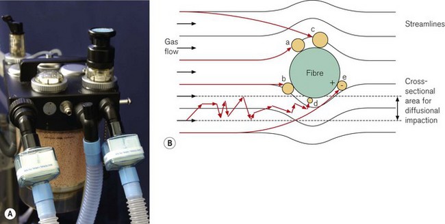
b Inertial impaction
Particles have mass and are, therefore, not always able to follow a gas streamline around a fibre due to their inertia. The particles may, therefore, strike the fibre, even though the gas streamline is more than one particle radius from the fibre.
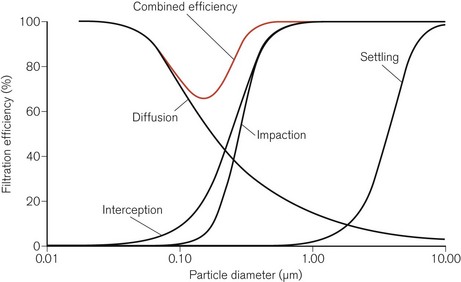
Most penetrating particle size
The relative efficiencies of the five mechanisms of filtration vary with the size of the particle (Fig. 11.2). In particular, particles of a certain size, typically in the range 0.05–0.5 µm, pass through the filter more easily than others. This size is known as the most penetrating particle size. Particles of this size are too small to be directly intercepted by fibres and too large to undergo substantial Brownian motion.
Types of filter
There are two main types of filter material used in breathing system filters:
Glass fibre filters
This filter material consists of a sheet of resin-bonded glass fibres. The fibres are packed densely (Fig. 11.3A) and hence the sheet has a high resistance to gas flow per unit area. A sheet with a large surface area is used to reduce the resistance to gas flow to an acceptable level. The sheet is then pleated to minimize the required volume, and hence dead space, for the housing. This type of filter material is hydrophobic and under normal clinical conditions, does not absorb water.
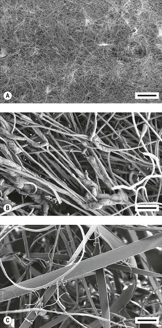
Electrostatic filters
1 Tribocharged filters
An electrostatic charge can be induced on two dissimilar fibres by rubbing them together during the manufacturing process, so that one type becomes positively charged and the other type negatively charged (tribocharging). One such filter material is made from fibres of polypropylene and modacrylic which can then be converted into a non-woven felt (Fig. 11.3B).
2 Fibrillated coronal-charged filters
An electrostatic charge can be applied to a sheet of polypropylene by using a point electrode emitting ions (corona charging). An opposite charge can be induced on the rear of the sheet. This type of material is often called an electret. If the sheet of polypropylene is now stretched, the strength of the molecular bonds is enhanced in the direction of the stretching, but reduced in a direction perpendicular to it. The sheet can then be split into fibres – a process called fibrillation – and made into a non-woven filter wad (Fig. 11.3C).
Measuring the performance of breathing system filters
The filtration efficiency of a filter is determined by measuring the number of particles passing through the filter as a percentage of the number of particles in an aerosol challenge to the filter. This percentage is the penetration value for the filter. Although challenges of microbes can be used,6 the standard for breathing system filters specifies that the challenge should consist of a particular quantity of an aerosol containing sodium chloride particles having diameters close to the most penetrating particle size.7 The filter is challenged at a flow of 15 or 30 L min−1 for filters intended for use with paediatric or adult patients, respectively. Typical penetration values for filters are shown in Fig. 11.4.
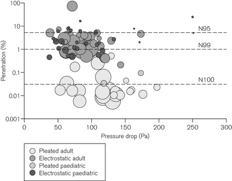
Figure 11.4 Penetration through 104 different filters when challenged with an aerosol of sodium chloride particles at the most penetrating particle size against pressure drop measured across the filter (100 Pa ≈ 1 cm H2O). Filters were tested at flows of 15 l min−1 (paediatric) or 30 l min−1 (adult), respectively. The size of each bubble is proportional to the internal volume of the filter. An ideal filter would have low values for penetration, pressure drop and internal volume (a small ‘bubble’ in the lower left hand side of the figure). However, filters with low penetration (high filtration efficiency) and low-pressure drop tend to be large filters; smaller filters tend to have higher pressure drops and higher penetration values (low filtration performance). N95, N99 and N100 refer to filtration efficiencies: namely <5%, <1% and <0.03% penetration respectively.
Adapted from Wilkes AR. Heat and moisture exchangers and breathing system filters: their use in anaesthesia and intensive care. Part 1 – history, principles and efficiency. Anaesthesia 2011;66:31-39 with permission from Wiley-Blackwell.
Humidifiers
Humidity
Humidity is used to describe the amount of water vapour in air or gas. The mass of water vapour in the gas is the absolute humidity (g m−3). The maximum amount of humidity that gas can contain is limited by temperature (Fig. 11.5). At the maximum humidity for a particular temperature, the gas is said to be saturated with water vapour, and the level of humidity is the humidity at saturation. The relative humidity (RH; %) is the absolute humidity of the gas at a particular temperature as a percentage of the humidity at saturation at the same temperature.
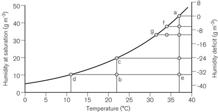
Room air at 22°C typically has an absolute humidity level of approximately 10 g m−3. The humidity at saturation of air at 22°C is approximately 20 g m−3, so that the room air has a relative humidity of approximately 50% RH. If the air is cooled, a point is reached at about 11°C when the absolute humidity level equals the humidity at saturation, and hence the relative humidity is 100%. If the air cools to an even lower temperature, condensation will occur. If room air is inspired, the air is warmed to 37°C by the upper air passages by the time it reaches the lungs, and the humidity is increased from 10 to 44 g m−3 (BTPS conditions: body temperature and pressure, saturated). The difference between the two (−34 g m−3) is the humidity deficit: humidity must be added by the airways to reduce this deficit to 0 g m−3. If the room air is warmed from 22 to 37°C without any humidification, the relative humidity will fall to 100 × (10 ÷ 44) = 23%. The massic enthalpy (latent heat) of evaporation of water is 2.4 kJ g−1. To saturate inspired gasses, which have a low level of humidity, a considerable proportion of the body’s heat production must be used (up to one-third for a neonate). This can then lead to a fall in the patient’s core temperature of more than 1°C.
Humidification requirements
The level of humidity acceptable in gasses delivered to patients whose upper airways have been bypassed depends on the length of time of the bypass. For short-term use the level of humidity may only need to be 20 g m−3 (45% of BTPS conditions).8 For longer use, for example, for patients in intensive care units, the level of humidity should be at least 33 g m−3 (75% of BTPS conditions).9 One group has proposed that the level of humidity should be close to BTPS conditions (44 g m−3).3
Humidification equipment
Passive humidification systems
1 Heat and moisture exchangers (HMEs)
These devices generally consist of a transparent plastic housing so that any obstructions and secretions in the device can be seen readily. The housing contains a layer of either foam or paper that is commonly coated with a hygroscopic salt such as calcium chloride. The expired gas cools as it passes through this layer and condensation occurs, releasing the massic enthalpy of vaporization, which is partly retained by the HME layer. The hygroscopic salt absorbs water vapour, hence reducing the relative humidity of the gas to below saturation level, although some moisture is always lost into the breathing system. During inspiration, the humidity level of the gas entering the HME is usually low, so that the condensate evaporates using the absorbed heat, which also warms the gas. The hygroscopic salt, to which the water molecules are loosely bound, releases the water molecules when the water vapour pressure is low. The inspired gas is, therefore, warmed and humidified to an extent that depends on the moisture content of the expired gas, and, hence, on the patient’s core temperature.
Classification of filters and heat and moisture exchangers
There are, therefore, five broad types of filter and/or heat and moisture exchange devices (Fig. 11.6):
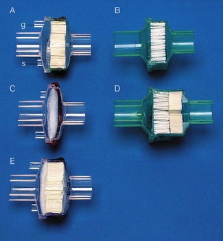
• A heat and moisture exchange-only device, without a filter layer
• A filter-only device, without a heat and moisture exchange layer, which can be either:


• Combined devices with both a heat and moisture exchange layer and a filter layer (HMEF), which can be either:


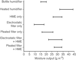
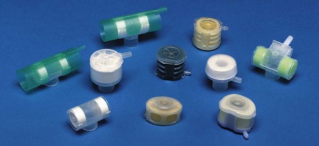
The range of typical levels of moisture output available is shown in Fig. 11.7. Devices available from some manufacturers are colour-coded to indicate particular types of device (Fig. 11.8).
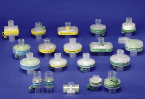
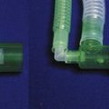
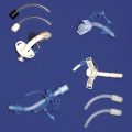
Filters and HMEs are available with different connectors. These include angle-pieces, catheter mounts and gas sampling ports. The gas sampling port is a female Luer-lock connector. When the cap on the port is removed, it can be placed on a storage port (if one is available) or, preferably a tether prevents the cap from becoming mislaid. HMEs are also available that are intended to be connected to a tracheostomy tube (Fig. 11.9).
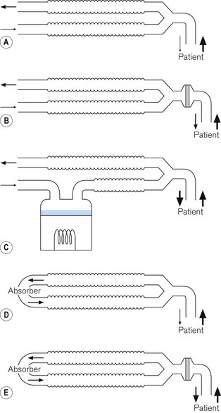
2 Circle breathing systems
In these breathing systems, a portion of the exhaled gas is usually returned to the inspiratory limb of the breathing system in order to recycle the anaesthetic agents. This gas is first passed through a container of absorbent in order to remove the exhaled carbon dioxide. This reaction generates both heat and water (see Chapter 5).
The removal of one mole of carbon dioxide from exhaled gas generates one mole of water. If all this water vaporizes, and assuming ideal gas conditions exist, an identical volume of water vapour will replace the volume of carbon dioxide. If the exhaled gas contains 5% carbon dioxide, sufficient water vapour could be produced to saturate gas at 33°C, as saturated gas at 33°C contains 5% water vapour by volume (36 g m−3 water vapour). This is much more than the minimum of 20 g m−3 recommended when the upper airways are bypassed during short-term procedures.8 Hence, provided low fresh-gas flows are used with the circle breathing system (so that the humidity in the gas is not diluted excessively by the dry fresh-gas), adequate levels of humidity may be produced by the circle system alone (Fig. 11.10). During anaesthesia, the humidity of the gas in the circle system therefore increases, although it may take up to 1 hour or more to reach a maximum level. The humidity in the breathing system will augment the moisture content of the gas delivered to the patient from a filter or HME sited at the patient connection port.10
Active humidification systems
In these devices, water vapour is added to the inspired gasses independently of the patient.
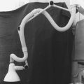
1 Bottle humidifier
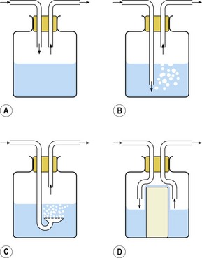
The simplest type of active humidifier is the bottle humidifier (Fig. 11.11). In its simplest form, gas is directed over the surface of the water (Fig. 11.11A). The water evaporates and the water vapour mixes with the gas, increasing its humidity. The process is inefficient in that, unless the gas flow is very low, there is not sufficient time for the gas to become saturated with water vapour before it leaves the humidifier. The efficiency of humidification can be improved by increasing the surface area for evaporation. This can be achieved by bubbling the gas through the water, either through a tube (Fig. 11.11B) or through a sintered filter (Fig. 11.11C), or by placing a wick into the water: water is drawn up the wick again increasing the surface area for evaporation (Fig. 11.11D). Bubbling gas through the water increases the pressure drop across the device, and the resistance to gas flow may, therefore, be unacceptably high for a spontaneously breathing patient who is required to draw gas through the humidifier.
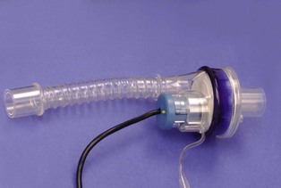
2 Active heat and moisture exchanger
In this device, there is a heat and moisture exchange layer that retains and returns a portion of the exhaled heat and moisture as with passive versions. However, there is also a source of water that is heated within the device so that additional water vapour can be added to the inspiratory gasses. One version of the device can be used with any HME or HMEF, and, therefore, if a filter is used, the patient can be protected from inhaling any infective droplets (Fig. 11.12). This device adds about 5 g m−3 to the humidity provided by the HME or filter with which it is used.11
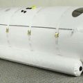
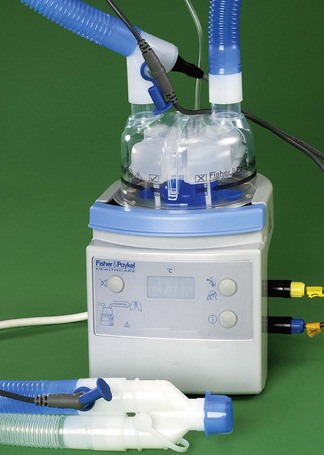
3 Heated humidifiers
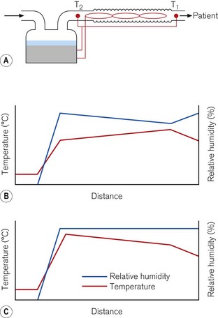
Heated humidifiers typically consist of the following (Fig. 11.13). Water is heated in a chamber that includes a wick, which absorbs the water and increases the surface area for evaporation. The water vapour produced mixes with the supplied gas as it flows through the humidifier. The water lost by evaporation is either manually or automatically replenished from a reservoir. The humidified gas then flows to the patient through a delivery tube, which contains a sensor that monitors the temperature of the gas at the patient end. The desired temperature of the delivered humidified gas is set using a control knob on the humidifier. If this gas is allowed to cool as it flows through the delivery tube, condensation may occur. To reduce this cooling, a heater wire in the delivery tube maintains the temperature of the gas. The temperature of the gas at the outlet of the humidification chamber is also monitored. The difference in temperature between the humidification chamber and the patient connection port is set on a second control knob. If the heater wire increases the temperature of the gas as it flows through the delivery tube, the risk of condensation forming is reduced, but the relative humidity of the gas also decreases. Alternatively, if the temperature of the gas falls, because of the settings on the two knobs, some condensation will occur, but the gas remains fully saturated with water vapour (Fig. 11.14).
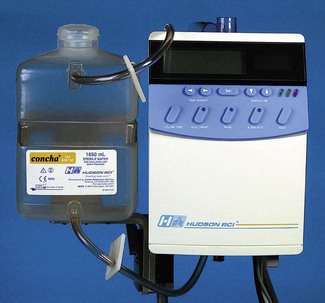
In one type of humidifier, the user has only to select whether the patient is intubated or receiving humidified gasses via a facemask. The temperature and humidity of the gasses are then controlled by the humidifier to provide the optimum level for the patient. The humidifier controls the humidity and temperature and also takes into account the flow of gas (Fig. 11.15).
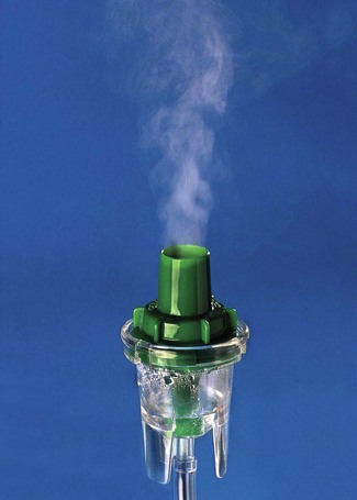
Nebulizers
Nebulizers are used to humidify respirable gasses by generating aerosols containing droplets of water from a reservoir of water (Fig. 11.16). The water may additionally contain medication. Some of these droplets evaporate as the gas flows to the patient so that the gas is likely to be fully saturated with water vapour when it reaches the patient’s airways. However, as heat is required for evaporation, the temperature of the gas will fall. The temperature can be increased by warming the water in the reservoir.
1 Gas-driven nebulizers
These devices use the Bernoulli principle (see Fig. 7.13) to force driving gas under pressure to entrain water into the system from a reservoir. The water is sucked into the gas stream and is broken up into droplets by the high flow of gas. An anvil, placed in the path of the flow of gas, breaks up the larger droplets into smaller ones, suitable for delivery to the patient (Fig. 11.17A).
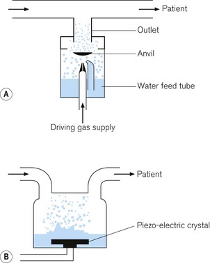
2 Ultrasonic nebulizer
In this device, a plate containing a piezo-electric crystal vibrates at an ultrasonic frequency, typically around 2 MHz. Water is either dropped onto the plate, or the plate is placed in the water. The frequency of oscillations of the plate causes the water to break up into droplets. Gas flowing into the nebulizing chamber picks up the droplets to deliver them to the patient (Fig. 11.17B).
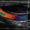
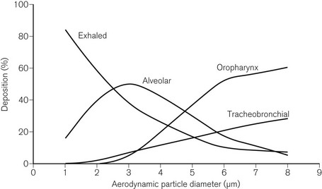
Deposition in the airways
Deposition of droplets in the airways depends on similar mechanisms as deposition of particles in filters (see above). Deposition, therefore, depends on the size of the droplets. Droplets with a diameter greater than 5 µm are deposited in the upper airways (gravitational settling), droplets with a diameter in the range of 2–6 µm are deposited in the tracheobronchial airways (interception), and droplets with a diameter in the range of 0.5–3 µm are deposited in the alveoli (inertial impaction and diffusion) (Fig. 11.18).12 As with particles and filters, deposition and retention of droplets within the airways is a minimum for droplets with an aerodynamic diameter of about 0.3 µm. The mass of the droplets is also important. The mass of the droplet is proportional to r3, where r is the radius. A droplet with 10 times the radius will carry 1000 times the mass, or 1000 times the medication. Deposition increases for droplets with diameters less than 0.3 µm due to Brownian motion. However, droplets of this size carry only a very small mass of medication.
Deposition in the alveoli, particularly when breathing nasally, is a small fraction of the overall deposition. Deposition in the alveoli will be greater during oral breathing and particularly when the upper airways are bypassed.
Problems with filters, humidifiers and nebulizers
Filters and HMEs also increase the resistance to gas flow in a breathing system. Also, if the dead space is reduced, by using a smaller device, the resistance to gas flow increases, and the filtration efficiency and moisture output decreases. Filters can block if excessive water or sputum enter the housing, preventing adequate ventilation of the patient.13,14
With nebulizers, it is relatively easy to add a large amount of moisture to the delivered gas, leading to excessive loading of the lungs with water and subsequent hypoxia due to blockage of the alveoli. In addition droplets of the sizes produced are very effective carriers of microbes, so care must be taken to ensure that the liquid water in the nebulizer is sterile. Some nebulized drugs can block some types of filter.15 Also if the nebulizer is operating continuously then a proportion of the medication will also be lost into the expiratory limb of the breathing system during exhalation. This proportion depends on the inspiratory : expiratory ratio of the breathing pattern.
1 Burton JDK. Effects of dry anaesthetic gasses on the respiratory mucous membrane. Lancet. 1962;i:235–239.
2 Chalon J, Loew DAY, Malebranche J. Effects of dry anesthetic gasses on tracheobronchial ciliated epithelium. Anesthesiology. 1972;37:338–343.
3 Williams R, Rankin N, Smith T, Galler D, Seakins P. Relationship between the humidity and temperature of inspired gas and the function of the airway mucosa. Crit Care Med. 1996;24:1920–1929.
4 Rathgeber J, Keitzmann D, Mergeryant H, Hub R, Zuchner K, Kettler D. Prevention of patient bacterial contamination of anaesthesia-circle-systems. A clinical study of the contamination risk and performance of different heat and moisture exchangers with electret filter (HMEF). Eur J Anaesthesiol. 1997;14:368–373.
5 Wilkes AR. The ability of breathing system filters to prevent liquid contamination of breathing systems: a laboratory study. Anaesthesia. 2002;57:33–39.
6 Wilkes AR, Benbough JE, Speight SE, Harmer H. The bacterial and viral filtration performance of breathing system filters. Anaesthesia. 2000;55:458–465.
7 Wilkes AR. Measuring the filtration performance of breathing system filters using sodium chloride particles. Anaesthesia. 2002;57:162–168.
8 Kleemann PP. Humidity of anaesthetic gasses with respect to low flow anaesthesia. Anaesth Intensive Care. 1994;22:396–408.
9 British Standards Institution. Respiratory tract humidifiers for medical use – Particular requirements for respiratory humidification systems (BS EN ISO 8185: 2009). London: British Standards Institution; 2009.
10 Henriksson B-Å, Sundling J, Hellman A. The effect of a heat and moisture exchanger on humidity in a low-flow anaesthesia system. Anaesthesia. 1997;52:144–149.
11 Medical Devices Agency. ‘Active’ heat and moisture exchanger: Tomtec HME-Booster (Evaluation 01029). London: Medical Devices Agency; 2001.
12 British Standards Institution. Respiratory therapy equipment – Part 1: Nebulizing systems and their components (BS EN 13544–1: 2001). London: British Standards Institution; 2001.
13 Williams DJ, Stacey MRW. Rapid and complete occlusion of a heat and moisture exchange filter by pulmonary edema (Clinical report. Can J Anaesth. 2002;49:126–131.
14 Lawes EG. Hidden hazards and dangers associated with the use of HME/filters in breathing circuits. Their effect on toxic metabolite production, pulse oximetry and airway resistance. Br J Anaesth. 2003;91:249–264.
15 Stacey MRW, Asai T, Wilkes A, Hodzovic I. Obstruction of a breathing system filter. Can J Anaesth. 1996;43:1276.
Branson RD, Campbell RS, Davis K, Porembka DT. Anaesthesia circuits, humidity output, and mucociliary structure and function. Anaesth Intensive Care. 1998;26:178–183.
Branson RD, Peterson BD, Carson KD. Humidification: current therapy and controversy. editors. Respir Care Clin N Am. 1998;4:189–344.
Brown RC. Air filtration. An integrated approach to the theory and applications of fibrous filters. Oxford: Pergamon Press; 1993.
Hinds WC. Aerosol technology. Properties, behavior, and measurement of airborne particles, 2nd ed. New York: John Wiley and Sons; 1999.
Kramer A, Kranabetter R, Rathgeber J, Züchner K, Assadian O, Daeschlein G, et al. Infection prevention during anaesthesia ventilation by the use of breathing system filters (BSF): joint recommendation by German Society of Hospital Hygiene (DGKH) and German Society for Anaesthesiology and Intensive Care (DGAI). GMS Krankenhaushygiene Interdisziplinär. 2010;5:1–19.
MHRA Evaluation 04005. Breathing System Filters. An assessment of 104 breathing system filters. HMSO. London 2004.
Muers MF. Overview of nebuliser treatment. Thorax. 1997;52:S25–S30.
O’Callaghan C, Barry PW. The science of nebulised drug delivery. Thorax. 1997;52:S31–S44.
Shelly MP. Humidification. In: Intensive care rounds. Abingdon: The Medicine Group (Education) Ltd; 1993.
Wilkes AR. Humidification: its importance and delivery. Br J Anaesth CEPD Rev. 2001;1:40–43.
Wilkes AR. Breathing system filters. Br J Anaesth CEPD Rev. 2002;2:151–154.
Wilkes AR. Heat and moisture exchangers and breathing system filters: their use in anaesthesia and intensive care. Part 1 – history, principles and efficiency. Anaesthesia. 2011;66:31–39.
Wilkes AR. Heat and moisture exchangers and breathing system filters: their use in anaesthesia and intensive care. Part 2 – practical use, including problems, and their use with paediatric patients. Anaesthesia. 2011;66:40–51.