Bones and joints
Imaging modalities
1. Plain films. These are cheap, widely available and valuable screening tools in the preliminary assessment of osteoarticular symptoms. Standard views require a minimum of two views perpendicular to each other, e.g. antero-posterior and lateral projections. The pathological processes underlying osteolysis and osteosclerosis, e.g. infection, tumours, articular erosions, etc., are well advanced before they become radiographically visible and radiographs may appear normal despite the presence of significant bone and joint disease. Although there are limitations, plain films are very useful in the characterization and differential diagnosis of disease, e.g. trauma, bone tumours, arthritis. Despite the recent advances in imaging techniques, the radiograph remains the single most important investigation in the characterization of bone tumours.
2. Arthrography. The injection of radiographically positive (iodinated) and negative (air) contrast medium directly into the joint allows radiographic assessment of articular structures in conventional arthrography. The examination can then be supplemented with CT (CT arthrography) which provides more detailed assessment of intra-articular status and structures using bone and soft-tissue window settings. For optimal evaluation, reformatted CT images in three planes with MDCT are obtained. Arthrography using a dilute gadolinium-DTPA solution and imaging with MRI (MR arthrography) is increasingly used in the study of large joint disease, e.g. shoulder, hip and, to a lesser extent, wrist, elbow and ankle.
3. Radionuclide imaging. Bone scintigraphy enjoys a high sensitivity but a low specificity. It is widely used in the detection and follow-up of metastatic disease, characterization of lesions shown by other imaging modalities, and as a sensitive test for the detection of pathology such as infection.
4. Ultrasound (US). Advances in US technology have increasingly been applied to musculoskeletal disorders in both adult and paediatric age groups. Peri-articular structures (capsule, ligaments, and tendons) are optimally imaged. Under US-guidance, therapy to soft-tissue disease can be accurately targeted, joint fluid aspirated and arthrographic agents instilled into joints.
5. Computed tomography (CT). This is very useful in complex bone trauma for accurate surgical planning and also in many applications in assessment of bone tumours and infection. Joint anatomy and pathology in joints which are difficult to image in two perpendicular planes and in which there is bone overlap, e.g. shoulder, hip, sternoclavicular, sacroiliac joints are best depicted using CT. When employed in CT arthrography, the intra-articular status of joints can be optimally assessed.
6. Magnetic resonance imaging (MRI). MRI is the best imaging modality for joint assessment. In many joints, e.g. knee, it can be employed as the first and only means of imaging. In other joints, e.g. shoulder, MRI alone is used to image the rotator cuff, but MR arthrography is required for optimal imaging of the ligaments, capsule and labrum in post-traumatic instability. Direct MR arthrography using intra-articular injection of dilute gadolinium solution is also employed, in the hip primarily to image the labrum and in the wrist to assess the interosseous ligaments of the proximal carpal row and the triangular fibrocartilage. Indirect MR arthrography following intravenous (i.v.) injection of gadolinium-DTPA, which quickly diffuses into the joint via the synovium, is used in the detection and quantification of active synovitis, e.g. rheumatoid arthritis. This is particularly of value in small joints and in the post-operative assessment of large joints. MRI is widely used in the assessment of bone pathology such as tumour or infection.
Musculoskeletal magnetic resonance imaging – general points
1. The large variety of MR sequences provides an opportunity to tailor the sequences to the tissues that need to be optimally imaged. See Table 12.1.
Table 12.1
Optimizing magnetic resonance imaging sequences for musculoskeletal tissues
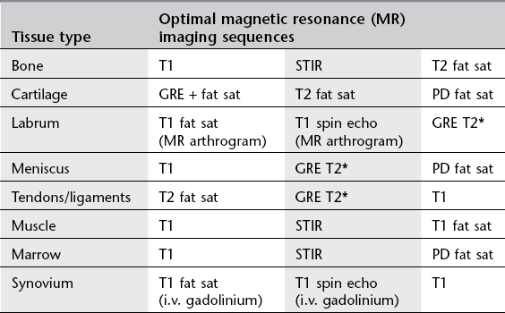
STIR = short tau inversion recovery; GRE = gradient echo; PD = proton density.
2. I.v. gadolinium-DTPA is used in musculoskeletal imaging for:
(a) infections – to differentiate abscess from phlegmon
(b) tumours – to differentiate viable tumour from necrosis – to differentiate solid from cystic components
(c) post-operative spine – to differentiate recurrent disc herniation from scar tissue
(d) synovial disease, e.g. rheumatoid arthritis – to determine activity/response to treatment
(e) avascular necrosis, e.g. Perthes’ disease, scaphoid fracture – to show viable tissue
(f) indirect MR arthrography – to delineate articular cartilage status, meniscal repair.
3. MR arthrography. Direct MR arthrography involves joint puncture and the intra-articular injection of a dilute gadolinium solution (saline and local anaesthetic can also be used). The amount of gadolinium needed to produce contrast by shortening the T1 effect of fluid is very small and too much gadolinium-DTPA results in signal loss of the fluid (‘black out’). Gadolinium-DTPA is, therefore, diluted in a ratio of 1 : 100 with sterile saline solution before use. The joint is distended and the recesses filled, delineating the intra-articular structures and separating them from adjacent tissues. In the lower limb, it allows accurate visualization of the labrum of the hip, the operated meniscus in the knee, and the impingement ankle syndromes, demonstrating associated osteochondral defects, loose bodies and synovial pathology more reliably than conventional MRI. In the upper limb, it is mostly utilized in the unstable shoulder to assess the damaged osteoarticular structures, the elbow and wrist joints. T1 spin echo and T1 fat-saturated sequences are used routinely in MR arthrography along with a T2 sequence in at least one plane to detect cysts, bone and soft-tissue oedema. Traction applied to joints at MR arthrography improves visualization of certain structures, e.g. long head of biceps origin in the shoulder, articular cartilage in the hip. MR arthrography avoids the requirement for diagnostic arthroscopy and aids in the therapeutic plan.
Arthrography – general points
1. The conventional radiographs should always be reviewed prior to the procedure.
2. Aspiration of an effusion should always be performed before contrast medium is injected. The aspirate should be sent, where appropriate, for microscopy, culture (aerobic and anaerobic) and sensitivity, crystal analysis, cytology and biochemistry.
3. Conventional arthrography has largely been replaced by MRI, e.g. knee. It is still the mainstay for diagnosing adhesive capsulitis, and in demonstrating the exact site of abnormal articular communications, e.g. wrist and foot. Most arthrograms are currently carried out as a prelude to either CT or MR arthrography.
4. If a needle is correctly sited within a joint space, a test injection of a small volume of contrast medium will stream away from the needle tip around the joint. However, if it is incorrectly sited, the contrast medium will remain in a diffuse cloud around the tip of the needle. For this reason, it is important that the fluoroscopy-guided needle approach should aim to visualize the needle tip at all times during its trajectory. In the knee, fluoroscopy in the AP plane is used as the needle is advanced from a lateral approach; fluoroscopy of the ankle in the lateral projection allows needle-tip visualization as it is advanced via an anterior approach.
5. Needle placement may be ‘blind’ or under image guidance, e.g. fluoroscopy, CT, CT fluoroscopy or US. Measured effective doses given by an experienced radiologist show significant differences; in shoulder arthrography – fluoroscopy (0.0015 mSv), single slice CT (0.18 mSv) and CT fluoroscopy (0.22 mSv).1
6. The positive contrast medium is absorbed from the joint and excreted from the body in a few hours. However, intra-articular air may take up to 4 days to be completely absorbed from the joint space. Every effort should be made to eliminate air bubbles at injection for MR arthrography as they create artifacts.
7. Arthrography is well tolerated by patients with discomfort rated less severe than general MRI-related patient discomfort.2
8. Arthrography is a very safe procedure with low complication rates. In a major study there were 3.8% minor complications (vasovagal reaction, pain, synovitis) and 0.02% major complications (anaphylactic reaction, infection, vascular).3 This included 13 300 MR arthrograms with only a 0.03% complication rate, all of which were minor.
9. In the scheduling of CT and MR arthrography it is important to ensure that the examination is carried out within 30 min of fluoroscopy-guided contrast medium intra-articular instillation. After this time contrast medium absorption will result in a suboptimal examination with resultant difficulties in interpretation.
Arthrography
Indications
1. Intra-articular structures, e.g. cartilage, labrum and tendons. The exact status of cartilage overlying osteochondritis dissecans (knee, ankle), labral tears (shoulder and hip) and anchor point of the long head of biceps requires CT or MR arthrography for accurate diagnosis.
2. Capsular, ligamentous and tendon injuries. Information regarding the presence, type, extent, gap and edges of torn capsular and peri-capsular structures (glenohumeral ligaments, rotator cuff tendons, lateral ankle ligaments) requires CT/MR arthrography.
3. Loose body. Loose bodies can be solitary or multiple, radiolucent or radio-opaque. CT arthrography using dilute contrast medium solution best depicts radiolucent bodies. Double-contrast CT arthrography using only a small amount of positive contrast medium is best to delineate radio-opaque loose bodies, determine true size and assess articular status of the joint.
4. Para-articular cyst. Synovial cysts and ganglia within para-articular soft tissues and bones can present with space-occupying lesions, which may migrate some distance away from the joint source of origin (popliteal cysts, iliopsoas bursa). Arthrography can demonstrate the articular communication either immediately or on delayed imaging.
5. Prosthesis assessment, e.g. loosening, infection. Arthrography demonstrates abnormal interposition of contrast medium indicating loosening at the cement/bone or metal/bone interface depending on the type of arthroplasty procedure carried out, while joint irrigation and aspiration fluid specimens are needed to confirm associated infection. Subtraction radiographic techniques are employed to facilitate interpretation, as the metal prosthesis and the barium-impregnated cement are subtracted out of the final image.
6. Pain block, e.g. bupivacaine ± steroid therapy. For difficult therapeutic decisions, diagnostic tests to confirm the pain source origin are increasingly being employed by instilling 0.5% bupivacaine intra-articularly. The addition of a steroid preparation can also aid in a longer period of pain control. If required, the injectate may act as the arthrographic agent for MRI done immediately after the pain block.
7. Confirm location of calcified para-articular soft-tissue masses. Calcified or ossified soft-tissue lesions in a para-articular location may or may not be intra-articular (e.g. synovial osteochondromatosis, myositis ossificans) requiring CT arthrography to help in their accurate localization.
8. Diagnosis and distension therapy in adhesive capsulitis. Usually employed in the shoulder in the treatment of frozen shoulder, the combination of anaesthetic, steroid and saline can be used to distend and rupture the joint after arthrographic confirmation of the diagnosis.
9. Intra-articular chemical therapy, e.g. hyaluronic acid, fibrinolysis, radioactive synovectomy. The intra-articular injection of hyaluronic acid in joints suffering from mild to moderate osteoarthritis produces viscosupplementation of joint fluid, reducing pain and increasing the articular cartilage thickness. In fibrin-laden effusions due to chronic rheumatoid arthritis, injected intra-articular fibrinolytic agents aid in the aspiration of the joint fluid.
Contraindications
2. Allergy to iodine or gadolinium
3. Contraindication to MRI (see Chapter 2); consider CT arthrography.
Contrast medium
Radiographic views
1. AP and lateral views are routinely obtained after arthrography.
2. Additional axial (e.g. shoulder) and oblique (e.g. ankle) views may be helpful.
3. Dynamic assessment under fluoroscopic imaging with stress views may be useful, e.g. inversion/eversion in the ankle; abduction/adduction, weight-bearing views of the shoulder.
4. Erect posture with external and internal rotation views in double-contrast shoulder studies.
5. Radial and ulnar deviation views in radio-carpal, midcarpal and inferior radio-ulnar joints.
References
1. Binkert, CA, Verdun, FR, Zanetti, M, et al. CT arthrography of the glenohumeral joint: CT fluoroscopy versus conventional CT and fluoroscopy – comparison of image guidance techniques. Radiology. 2003; 229:153–158.
2. Binkert, CA, Zanetti, M, Hodler, J. Patient’s assessment of discomfort during MR arthrography of the shoulder. Radiology. 2001; 221:775–778.
3. Hugo, PC, Newberg, AH, Newman, JS, et al. Complications of arthrography. Sem Musculoskelet Radiol. 1998; 2(4):345–348.
Andreisek, G, Duc, SR, Froehlich, JM, et al. MR arthrography of the shoulder, hip, and wrist: evaluation of contrast dynamics and image quality with increasing injection-to-imaging time. Am J Roentgenol. 2007; 188(4):1081–1088.
Tehranzadeh, J, Mossop, EP, Golshan-Momeni, M. Therapeutic arthrography and bursography. Orthop Clin North Am. 2006; 37(3):393–408.
Arthrography – site-specific issues
Knee
Technique
1. The patient lies supine; either a medial or a lateral approach can be used and it is as well to be familiar with both.
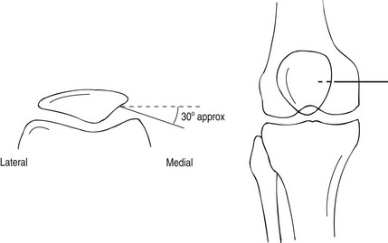
2. Using a sterile technique, the skin and underlying soft tissue are anaesthetized at a point 1–2 cm posterior to the mid-point of the patella.
3. A 21G needle is advanced into the joint space from this point by angling it slightly anteriorly so the tip comes to lie against the posterior surface of the patella. By virtue of the anatomy, the tip of the needle must be within the joint space (Fig. 12.1). A more horizontal approach may result in the needle penetrating the infra-patellar fat pad, resulting in an extra-articular injection of contrast.
4. Any effusion is aspirated. A test injection of a small volume of contrast medium can be made under fluoroscopic control to ensure the needle is correctly positioned and, if so, the contrast medium should be seen to flow rapidly away from the needle tip. If a satisfactory position is demonstrated, then the full volume of contrast medium (4 ml) and air (40 ml) may be injected for a double-contrast arthrogram.
5. The needle is then removed and the knee is manipulated to ensure even distribution of contrast medium within the joint; this is easily facilitated by asking the patient to walk around the room several times whilst bending the knee through as full a movement as possible.
6. The arthrogram is usually followed by CT to assess the patellofemoral articular status and its articular geometric relationship. Patellar tracking in different degrees of knee flexion can be done if needed. MDCT also assesses the medial and lateral articular and meniscal status optimally.
Hip
Technique
1. The patient lies supine on the X-ray table, the leg is extended and internally rotated, and the position maintained with sandbags so that the entire length of the femoral neck is visualized.
2. The position of the femoral vessels is marked to avoid inadvertent puncture.
3. The skin is prepared in a standard aseptic manner.
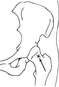
4. A metal marker (sterile needle) or a point on the skin is made to show the position of entry (Fig. 12.2) which should correspond to the midpoint of the inter-trochanteric line. After local anaesthetic infiltration a spinal needle (7.5 cm, 20 or 22G, short bevel) is then advanced vertically with mild forward angulation. The needle tip advances forward towards the femoral neck target under fluoroscopic control, aiming supero-laterally onto the femoral neck immediately below the junction of the femoral head with the neck laterally. The capsule may be thick and a definite ‘give’ felt when the needle enters the joint.
5. A test injection of contrast medium will demonstrate correct placement of the needle as it flows away from the needle tip. Any fluid in the joint should be aspirated at this stage and sent for analysis.
6. Approximately 6–8 ml (1–2 ml in children) of contrast medium is injected. The exact amount depends on the capacity of the joint capsule. In MR arthrography, dilute gadolinium solution is used for contrast. Alternatively in a pain block procedure, 6–8 ml of 0.5% bupivacaine is injected intra-articularly and this can also act as the contrast medium for a limited MR arthrogram relying on T2 sequences. If examining a prosthetic joint, larger volumes of contrast medium may be required (15–20 ml). By adding a radioactive tracer to the infusate (99mTc-colloid) and subsequent imaging with a gamma-camera, a more accurate assessment of loosening can be made, perhaps because the tracer is less viscous than the contrast medium and extends to a greater extent along the prosthesis.
7. After injection of the contrast medium, the needle is removed and the joint is passively exercised to distribute the contrast medium evenly. Radiographic views are taken immediately and the patient sent to CT or MR scanning suites accordingly.
Shoulder
Technique
1. There are various approaches to needle placement, e.g. anterior (superior or inferior), modified anterior, and posterior to the glenohumeral joint. In the commonly used anterior approach the patient lies supine, with the arm of the side under investigation close to the body and in external rotation. This is to rotate the long head of the biceps out of the path of the needle. The articular surface of the glenoid will face slightly forwards, which is important as it allows a vertically placed needle to enter the joint space without damaging the glenoid labrum.
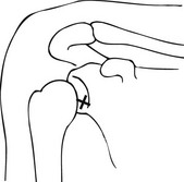
2. The coracoid process is an important landmark. Using a sterile technique, the skin and soft tissues are anaesthetized at a point 1 cm inferior and 1 cm lateral to the coracoid process. Position of needle entry point is optimized by fluoroscopy which also helps to ensure that the chosen needle trajectory is not impeded by an elongated coracoid process.
3. A spinal needle 21G needle is inserted vertically down into the joint space (Fig. 12.3). The vertical direction should intersect the junction of the middle and lower thirds of the cranio-caudal plane of the glenohumeral joint. This also allows precise control of the medio-lateral course of the needle. The position of the needle should be checked by intermittent screening. When it meets the resistance of the articular surface of the humeral head, it is withdrawn by 1–2 mm to free the tip. In the modified anterior approach where the needle traverses the rotator cuff interval, the needle is aimed towards the upper medial quadrant of the humeral head close to the articular joint line.
4. The intra-articular position of the needle is then confirmed by the injection of a small amount of the contrast medium under fluoroscopic control.
5. Then either the remainder of the iodinated contrast medium (15 ml in total) is injected for a single contrast examination, or sufficient air to distend the synovial sac (12 ml) is injected for a double-contrast examination. CT arthrography can be done after either type. In MR arthrography a dilute solution of gadolinium needs to be injected into the joint and this can be done by combining 1 ml of lidocaine, 2 ml of iodinated contrast medium (200 mg ml−1) and 12 ml of dilute gadolinium solution (2–2.5 mmol l−1). Sterile, premixed gadolinium-DTPA solutions are available for use in MR arthrography. Patients with an adhesive capsulitis may experience pain after much smaller amounts. If this is severe, then injection should be stopped. Resistance to injection is common, unlike injection into the knee, and more force is often required.
6. The needle is removed and the joint is gently manipulated to distribute the contrast medium.
7. CT arthrography examination is performed with the patient supine and positioned slightly eccentrically within the scanner to ensure that the shoulder is as close to the centre of the scanner as possible. The contralateral arm can be elevated above the head to minimize image artifacts. Scanning should be undertaken during arrested respiration to minimize motion artifact.
8. The area of interest in both CT/MR arthrography should include the acromion to the axillary recess. MDCT provides high-quality reformatted images in the three planes and MR images should also examine the joint in three planes. In addition when the arm is placed in the ABER position (abduction and external rotation), elegant MR views of the inferior capsule-labral complex and supraspinatus optimally study these structures.
Elbow
Technique
Single contrast
1. The patient sits next to the table with the elbow flexed and resting on the table, the lateral aspect uppermost.
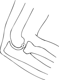
2. The radial head is located by palpation during gentle pronation and supination of the forearm. Using a sterile technique the skin and soft tissues are anaesthetized at a point just proximal to the radial head.
3. A 23G needle is then inserted vertically down into the joint space between the radial head and the capitellum (Fig. 12.4).
4. An injection of a small volume of local anaesthetic will flow easily if the needle is correctly sited. This can be confirmed by the injection of a few drops of contrast medium under fluoroscopic control.
5. The remainder of the contrast medium (6–8 ml) is injected and the joint gently manipulated to distribute it evenly.
Wrist
Technique
Radiocarpal joint
1. The patient is seated next to the screening table with the forearm resting in a neutral prone position. The wrist should be supported over a wedge with about 10–15° of flexion.
2. Using a sterile technique, the skin and soft tissues are anaesthetized at a point over the midpoint of the scapho-capitate joint (Fig. 12.5).
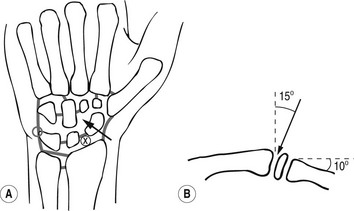
Figure 12.5 Technique of wrist arthrography. (a) AP view, x = point of entry to radiocarpal joint, arrow = point of entry to midcarpal joint. (b) Lateral view, arrow indicates cranial angulation required for needle with dorsal approach to radiocarpal joint.
3. A 23G needle is inserted into the joint by advancing it downwards and at an angle of about 15° proximally.
4. Contrast medium (2–4 ml) is injected under fluoroscopic control; if any leakage occurs into the midcarpal joint or distal radio-ulnar joints, then spot views should be taken. If this is not done, it is possible to miss small tears that later become obscured by the anterior and posterior extensions of the radiocarpal joint.
Midcarpal joint
1. The wrist is positioned as for radiocarpal injection, but with ulnar deviation, as this widens the joint space.
2. The skin and soft tissues are anaesthetized at a point over the mid-point of the scapho-capitate joint (Fig. 12.5).
3. A 23G needle is inserted vertically into the joint space under fluoroscopic control.
4. Contrast medium (2 ml) is injected under fluoroscopic control, ideally with video-recording facility, until the joint space is full. Without continuous monitoring it may not be possible to tell which of the ligaments separating the midcarpal from the radiocarpal joint are torn allowing interarticular communication.
Ankle
Technique
1. The patient lies in the lateral decubitus position with the ankle plantar-flexed. An anterior approach is used with fluoroscopic guidance of the needle with the ankle in the true lateral projection (Fig. 12.6).
2. Using a sterile technique, the skin is anaesthetized at a point midway to the bimalleolar distance which places the needle lateral to the dorsalis pedis artery.
3. A 21G needle is inserted and advanced into the anterior joint space and contrast medium injected to confirm correct needle position, and then to distend the joint (4–6 ml).
4. The availability of volume acquisition with MDCT allows reformatted images in the three planes, which can detect small cartilage defects.
5. If MDCT is not available the CT scanner gantry is tilted to obtain, as closely as is possible, true coronal sections through the ankle.
Coumas, JM, Palmer, WE. Knee arthrography. Evolution and current status. Radiol Clin North Am. 1998; 36(4):703–728.
De Filippo, M, Bertellini, A, Pogliacomi, F, et al. Multidetector CT arthrography of the knee: diagnostic accuracy and indications. Eur J Radiol. 2008; 70(2):342–351.
Mutschler, C, Vande Berg, BC, Lecouvet, FE, et al. Postoperative meniscus: assessment at dual detector row spiral CT arthrography of the knee. Radiology. 2003; 228(3):635–641.
Radiographic Views in the Paediatric Hip Arthrogram
Aliabadi, P, Baker, ND, Jaramillo, D. Hip arthrography, aspiration, block, and bursography. Radiol Clin North Am. 1998; 36(4):673–690.
Devalia, KL, Wright, D, Sathyamurthy, P, et al. Role of preoperative arthrography in early Perthes disease as a decision making tool. Is it really necessary? J Pediatr Orthop B. 2007; 16:196–200.
Grissom, L, Harcke, HT, Thacker, M. Imaging in the surgical management of developmental dislocation of the hip. Clin Orthop Relat Res. 2008; 466:791–801.
Llopis, E, Cerezal, L. Direct MR arthrography of the hip with leg traction: feasibility for assessing articular cartilage. Am J Roentgenol. 2008; 190(4):1124–1128.
Temmerman, OP, Raijmakers, PG, Deville, WL, et al. The use of plain radiography, subtraction arthrography, nuclear arthrography, and bone scintigraphy in the diagnosis of a loose acetabular component of a total hip prosthesis: a systematic review. J Arthroplasty. 2007; 22:818–827.
Chung, CB, Dwek, JR, Feng, S, et al. MR arthrography of the glenohumeral joint: a tailored approach. Am J Roentgenol. 2001; 177(1):217–219.
Dépelteau, H, Bureau, NJ, Cardinal, E, et al. Arthrography of the shoulder: a simple fluoroscopically guided approach for targeting the rotator cuff interval. Am J Roentgenol. 2004; 182(2):329–332.
Farmer, KD, Hughes, PM. MR arthrography of the shoulder: fluoroscopically guided technique using a posterior approach. Am J Roentgenol. 2002; 178(2):433–434.
Schneider, R, Ghelman, B, Kaye, JJ. A simplified injection technique for shoulder arthrography. Radiology. 1975; 114(3):738–739.
Dubberley, JH, Faber, KJ, Patterson, SD, et al. The detection of loose bodies in the elbow: the value of MRI and CT arthrography. J Bone Joint Surg Br. 2005; 87:684–686.
Steinbach, LS, Schwartz, M. Elbow arthrography. Radiol Clin North Am. 1998; 36(4):635–649.
Waldt, S, Bruegel, M. Comparison of multislice CT arthrography and MR arthrography for the detection of articular cartilage lesions of the elbow. Eur Radiol. 2005; 15:784–791.
Joshy, S, Ghosh, S, Lee, K, et al. Accuracy of direct MR arthrography in the diagnosis of triangular fibrocartilage complex tears of the wrist. Int Orthop. 2008; 32:251–253.
Linkous, MD, Gilula, LA. Wrist arthrography today. Radiol Clin North Am. 1998; 36(4):651–672.
Moser, T, Dosch, JC, Moussaoui, A, et al. Wrist ligament tears: evaluation with MRI and combined MDCT and MR arthrography. Am J Roentgenol. 2007; 188:1278–1286.
Ruegger, C, Schmid, MR, Pfirrmann, CW, et al. Peripheral tear of the triangular fibrocartilage: depiction with MR arthrography of the distal radioulnar joint. Am J Roentgenol. 2007; 188:187–192.
Tirman, RM, Weber, ER, Snyder, LL, et al. Midcarpal wrist arthrography for the detection of tears of the scapholunate and lunotriquetral ligaments. Am J Roentgenol. 1985; 144:107–108.
Cerezal, L, Abascal, F, García-Valtuille, R, et al. Ankle MR arthrography: how, why and when? Radiol Clin North Am. 2005; 43:693–707.
Davies, AM, Cassar-Pullicino, VN. Demonstration of osteochondritis dissecans of the talus by coronal computed tomographic arthrography. Br J Radiol. 1989; 62(744):1050–1055.
Schmid, MR, Pfirrmann, CW, Hodler, J, et al. Cartilage lesions in the ankle joint: comparison of MR arthrography and CT arthrography. Skeletal Radiol. 2003; 32:259–265.
Ultrasound of the paediatric hip
Technique
Developmental dysplasia of the hip
With US the unossified elements of the hip – femoral head, greater trochanter, labrum, triradiate cartilage – as well as the bony acetabular roof, can be identified in the first 6 months of life.1 After 9–12 months, the degree of ossification precludes adequate imaging by US and plain film radiography becomes superior. There are two main methods, static and dynamic, and both may be used during one examination.
Hip-joint effusion
Approximately 50% of children with acute hip pain have intra-articular fluid and the sensitivity of US for detecting effusion approaches 100%.3 With the child supine, the hip is scanned anteriorly with the transducer parallel to the femoral neck. Bulging of the anterior portion of the joint capsule can be readily identified.4 The normal distance between the bony femoral neck and the joint capsule is always less than 3 mm, and the difference between the affected and unaffected sides should not be greater than 2 mm.
References
1. Yousefzadeh, DK, Ramilo, JL. Normal hip in children: correlation of US with anatomic and cryomicrotome sections. Radiology. 1987; 165:647–655.
2. Clarke, NM, Harcke, HT, McHugh, P, et al. Real time ultrasound in the diagnosis of congenital dislocation and dysplasia of the hip. J Bone Joint Surg Br. 1985; 67:406–412.
3. Dörr, U, Zieger, M, Hauke, H. Ultrasonography of the painful hip. Prospective studies in 204 patients. Pediatr Radiol. 1988; 19:36–40.
4. Miralles, M, Gonzalez, G, Pulpeiro, JR, et al. Sonography of the painful hip in children: 500 consecutive cases. Am J Roentgenol. 1989; 152:579–582.
Thermoablation of musculoskeletal tumours
Thermocoagulation
In radiofrequency thermal ablation an alternating current of high-frequency radio waves (>10KHz) is emitted from an electrode tip and this dissipates its energy as heat within the surrounding tissues. It is the tissue around the electrode which is therefore the primary source of heat and not the electrode itself. In response to the RF stimulus ions within local biological tissues vibrate leading to ionic agitation. As a direct result of the ions’ attempt to change direction with the alternating electrical current, friction is created around the electrode tip creating heat which desiccates the soft tissues – ‘thermal ablation’.1 The amount of biological tissue that can be ablated is referred to as the ‘treatment zone’. Using an electrode tip length of 5 mm, a spherical thermoablation treatment zone of 1 cm is generated. Effective ablation in living bone is achieved with a temperature of 90° C at the active tip for 4–6 min.2
Rationale
Using CT guidance the target is accurately localized and its dimensions determined. Using a coaxial needle system and drill, a biopsy can be taken and the tip of a thermoablation probe optimally placed in the centre of the lesion. The heat generated causes tumour necrosis over a diameter of 1 cm.3 Multiple RF probe placements via multiple skin entry points are needed if the lesion is larger than 1 cm to provide the 1 cm wide ablated margin required to cover the entire lesion needed for successful treatment.4
Contraindications
1. Cardiac pacemakers are an absolute contraindication as they can be affected by the radiofrequency current.
2. Relative contraindications include lesions that are close to (less than 1 cm) neighbouring peripheral nerves, spinal nerves and spinal cord, although measures can be employed to reduce the risk of damage in treating such lesions. Lesions in the hands and feet also have an additional increased risk of skin damage if they lack an adequate soft tissue cover.
Equipment
1. The Bonopty system is used which incorporates a penetration outer cannula, an inner stylet, a coaxial drill and a coaxial biopsy needle.
2. A radiofrequency generator is the source of the electric current that passes to the electrode tip into the patient, and out through a grounding pad back to the generator.
3. A non-insulated single electrode tip between 0.5 mm and 10 mm in length. A multi-tined electrode system can also be used in larger lesions.
Biopsy
The specially designed biopsy needle is placed in the cannula and slowly advanced through the lesion taking a biopsy after confirming that it has negotiated the tumour tissue by CT images.5
References
1. Organ, LW. Electrophysiologic principles of radiofrequency lesion making. Appl Neurophysiol. 1976; 39(2):69–76.
2. Tillotson, CL, Rosenberg, AE, Rosenthal, DI. Controlled thermal injury of bone: report of a percutaneous technique using radiofrequency electrode and generator. Invest Radiol. 1989; 24(11):888–892.
3. Rosenthal, DI, Hornicek, FJ, Wolfe, MW, et al. Percutaneous radiofrequency coagulation of osteoid osteoma compared with operative treatment. J Bone Joint Surg. American Volume. 1998; 80(6):815–821.
4. Pinto, CH, Taminiau, AH, Vanderschueren, GM, et al. Technical considerations in CT guided radiofrequency thermal ablation of osteoid osteoma: Tricks of the trade. Am J Roentgenol. 2002; 179(6):1633–1642.
5. Cribb, GL, Goude, WH, Cool, P, et al. Percutaneous radiofrequency thermocoagulation of osteoid osteomas: factors affecting therapeutic outcome. Skeletal Radiol. 2005; 34(11):702–706.
6. Rimondi, E, Mavrogenis, AF, Rossi, G, et al. Radiofrequency ablation for non-spinal osteoid osteomas in 557 patients. Eur Radiol. 2012; 22(1):181–188.
Radionuclide bone scan
Indications
1. Staging of cancer and response to therapy, especially breast and prostate
2. Assessment and staging of primary bone tumours
3. Painful orthopaedic prostheses to differentiate infection from loosening
5. Trauma not obvious on X-ray, e.g. stress fractures
7. Avascular necrosis and bone infarction
8. Assessment of non-accidental injury in children
9. Metabolic bone disease for complications such as fractures
10. Arthropathies, e.g. rheumatoid
11. Reflex sympathetic dystrophy
12. Assessment of extent multifocal disorders such as Paget’s disease and fibrous dysplasia.
Technique
1. 99mTc-diphosphonate is injected i.v. When infection is suspected or blood flow to bone or primary bone tumour is to be assessed, a bolus injection is given with the patient in position on the camera. A three-phase study is then performed with arterial, blood-pool and delayed static imaging.
2. The patient should be encouraged to drink plenty and empty the bladder frequently to minimize radiation dose.
3. The bladder is emptied immediately prior to imaging to prevent obscuring the sacrum and bony pelvis.
4. Delayed static imaging is performed ≥2 h after injection: up to 4 h for imaging of extremities and up to 6 h for those patients on dialysis or in renal failure.
Images
Standard
High-resolution images are acquired with a pixel size of 1–2 mm:
1. The whole skeleton. The number of views will depend upon the field of view of the camera and whether a whole-body imaging facility is available. A point to consider is that whole-body images will have lower resolution than spot views over parts of the skeleton where the camera is some distance from the patient (unless a body-contour tracking facility is available), since resolution falls off with distance. Spot views should be overlapping.
2. Anterior oblique views of the thorax are useful to separate sternum and spine uptake.
3. For examination of the posterior ribs, scapula or shoulder, an extra posterior thorax view with arms above the head should be taken to move the scapula away from the ribs.
4. For imaging small bones and joints, magnified views should be taken, with a pinhole collimator if necessary.
5. SPECT can be useful for lesion localization, e.g. in vertebrae and joints, and to detect avascular necrosis.1 CT-SPECT fusion is likely to be even more helpful, analogous to the improved specificity and diagnostic confidence seen with PET-CT as opposed to PET alone.2
References
1. Murray, IP, Dixon, J. The role of single photon emission computed tomography in bone scintigraphy. Skeletal Radiol. 1989; 18:493–505.
2. Utsunomiya, D, Shiraishi, S, Imuta, M, et al. Added value of SPECT/CT fusion in assessing suspected bone metastasis: comparison with scintigraphy alone and nonfused scintigraphy and CT. Radiology. 2006; 238:264–271.

