Chapter 136 Basic Biomechanically Relevant Anatomy
Biomechanics
Vectors, Scalars, Bending Moments, and the Instantaneous Axis of Rotation
A vector is a force oriented in a fixed direction in three-dimensional space (as defined by the right-handed Cartesian coordinate system previously discussed). It possesses both magnitude and direction (i.e., force and velocity), and it may be broken down into its component vectors. A scalar is a quantity that is direction independent and possesses only magnitude (i.e., time, volume). A bending moment occurs when a force acts on a lever or moment arm. A bending moment, when applied to a point in space, results in a tendency to rotate about an axis. When these principles are applied to a vertebral body, the three-dimensional axis about which a bending moment causes the body to rotate; this is known as the instantaneous axis of rotation (IAR). The IAR is the axis about which a vertebral segment rotates at any given instant, and the IAR itself does not move during this instant of rotation or translation. It may be considered a fulcrum about which a segment moves. When a body moves in a plane, there is a point in the body or some extension of it that does not move, and the axis that passes perpendicular to the plane of motion and through this point is the IAR (as defined by White and Panjabi1). The IAR becomes the center of the Cartesian coordinate system used to define the motion. The IAR is dynamic, and as spinal movement occurs, the IAR of each involved segment moves. The location of the IAR depends on the manner in which it is determined and the theoretical foundation on which it is based, and it is therefore subject to error.
Free Body Analysis
Free body diagrams use the forces, moments, and IAR on various anatomic structures to isolate those forces and assign vectors, so that all the forces are represented. In that way, complex problems can be reduced to their component parts. It is then possible, for example, to determine the force necessary to stand upright or the increase in paraspinal and gluteal force required by leaning forward as in kyphosis. These diagrams help one to understand these complex problems. They also form the basis for understanding why tension band disruption may lead to kyphosis in either the cervical or lumbar spine. As the moment arm moves forward and increases, even small amounts of kyphosis (or loss of lordosis) can have large effects on the forces acting on the spine (Fig. 136-1).
Newton’s Laws
Spine surgery involves the application of force to the spine. Fundamental to understanding the stresses withstood by the spine is the concept of action and reaction.2 Newton’s three laws of motion describe how objects respond to external forces.
1. The first law is the law of inertia, which states that if an object is subject to no net force, it maintains a constant velocity.
2. The second law is the law of superimposition of forces, which states that the momentum of an object is equal in magnitude and direction to the vector sum of the forces acting on it.
3. The third law is the law of conservation of momentum. which states that when two objects collide, the overall momentum is constant such that for every action there is an opposite but equal reaction.
As the spine is subject to various loads, force couples are created (based on the third law of motion), and the vertebral segments may fail. When applying forces to the spine, these same concepts need to be considered. All instrumentation will fail in time, and therefore the bony alignment must respect the body and gravitational forces or it will fail more quickly. The biomechanical environment must maintain a load balance between the implant and tissue environment to improve implant longevity.
Hooke’s Law and Stress-Strain Curves
When external forces act on a solid at rest, the solid is deformed. According to Hooke’s law, for small displacements, the size of the deformation is proportional to the deforming force. For solids within the elastic zone, the relationship between deformation and force is linear. To make sense of Hooke’s law then as it applies to the spine, the concepts of stress-strain curves and deformation need to be expanded. Deformation of a solid can be either elastic or plastic. Elastic and plastic are defined by recovery once the deforming force is removed, and they exist on a spectrum that can be best illustrated with a deformation curve (Fig. 136-2). When a solid is subject to an external or deforming force, Hooke’s law applies only when the load and deformation occur within the elastic zone of the solid. The elastic zone is defined by elastic deformation, when a solid totally recovers after removal of a stress. Deformation continues to be proportional to the deforming force until the elastic limit of the solid is reached and the linear relationship between force and deformation no longer exists. Beyond the elastic limit of a material is the plastic zone, and this is the zone in which the solid acquires permanent deformation and does not completely recover once the stress is removed. As force continues to be applied, eventually the point of failure is reached. On a stress-strain curve (see Fig. 136-2), the area under the curve represents the amount of energy absorbed and the ultimate strength of a material (amount of energy required to reach failure). The neutral zone is an area of nonengagement where force is applied but deformation is minimal. It precedes the linear area of the curve.
Elastic Modulus
There are three types of elastic moduli:
1. Young’s modulus, which measures the elastic properties of an object when it is stretched or compressed
2. Shear modulus, which measures the shear deformation that occurs when transverse forces of opposite direction are applied at opposing faces of an object
3. Bulk modulus, which measures the deformation that occurs when a solid is squeezed
Section Modulus and Moment of Inertia
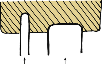
The section modulus is a concept that is calculated and used to define the strength of an object. It is applicable here with regard to spinal implants and instrumentation as an indicator of the overall strength and, more importantly, potential failure of an implant. The section modulus or strength of a screw is exponentially related to the diameter of the screw. As this diameter increases, the strength increases by the power to the fourth. This concept is also applicable to plate design. The strategy for hole placement for screws must be carefully designed because the holes reduce the section modulus. This then causes failure of the plate at a lower load (Fig. 136-3).

where T is stress, M is bending moment, and Z is section modulus. The bending moment (M) is also defined by an equation:

where M is bending moment, F is the force applied, and D is the distance of the moment arm through which the force is applied.
Basic Biomechanics of Bone
Bone fractures and the fracture patterns also follow the magnitude and direction of the forces applied. Wolff’s law, a theory developed by the German anatomist/surgeon Julius Wolff (1836–1902), states that bone adapts to imposed stress. If loading on a particular bone increases, the bone remodels itself over time to become stronger to compensate for greater load requirements.3
Rapidly applied loads to the spine may result in failure of the ligaments or bone, or both. The direction of force application, magnitude, and bony integrity all play a role in the fracture pattern and displacement. Several distinct failure patterns can be observed.
Avulsion Fracture
These occur as a result of the strong ligamentous attachments to the spine. The ligaments, which are strongest in tension due to their high collagen content, can avulse bony fragments (Table 136-1). An example of this is the bony avulsion seen with Jefferson burst fractures, where the transverse ligament avulses a portion of the lateral mass of C1.
| Ligament | Cervical (N) | Lumbar (N) |
|---|---|---|
| ALL | 112 | 450 |
| PLL | 75 | 324 |
| ISL | 240 | 125 |
| SSL | 36 | 150 |
ALL, anterior longitudinal ligament; ISL, interspinous ligament; PLL, posterior longitudinal ligament; SSL,supraspinous ligament.
From White AA, Panjabi MM: Clinical biomechanics of the spine, ed 2, Philadelphia, 1990, Lippincott, p 22.
Flexion-Distraction Fracture (Chance Fracture)
These fractures occur with a significant flexion moment, with the axis of rotation anterior to the spinal unit. This large moment (mass times acceleration times moment arm) results in a tremendous extension force to the spine. The mode of failure is tensile through the posterior elements and then progresses through the vertebral body. The classic example of this type of injury was described by Chance in 1948 and bears his name.4 The bony or ligamentous component of the fracture is determined by the difference between the tensile strength of the bone and ligaments, and the force travels through the path of least resistance.
Burst Fracture
The burst fracture typically has both axial load components as well as a flexion moment. Comminution is a function of the magnitude of force that was transmitted to the bone. It can be graded on the amount of the vertebral body that is involved and the amount of displacement. These grades have been used to understand the ability of that bone to support the anterior spine. Gaines described this load-sharing classification and the necessity for long-segment fixation or supplemental anterior support based on the concept of vertebral body comminution and fracture displacement.5 In healthy bone, this energy results in a burst pattern rather than a compression pattern. With failure of the anterior support, the spine falls into flexion with continued energy. The resultant disruption of the dorsal tension band or posterior bony fractures is usually the primary predictor of stability. Most classification systems recognize this, and posterior stability is a primary predictor of necessity of operative stabilization.6
Torsion
Complex fracture patterns often have a torsion component and can be responsible for fracture-dislocations with complete disruption of the anterior, middle, and posterior columns. Torsion injures are also common in the more flexible cervical spine. Typically, the failure is through the ligamentous structures because the oblique nature of the cervical facets allows for significant rotation. Torsional forces are the primary forces responsible for unilateral facet dislocations.7
Basic Anatomy of the Spine
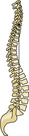
These curves function to increase the flexibility and shock-absorbing capacity of the spine. The overall physiologic alignment must be maintained to prevent construct failure and accelerated degeneration. Sagittal balance is an indicator of physiologic alignment and is particularly important in lumbosacral procedures. In a normal spine, a plumb line called the sagittal vertical axis (SVA) can be dropped from the C7 vertebral body through the lumbosacral junction (Fig. 136-4). If the SVA is ventral to the lumbosacral junction, it is called positive sagittal balance; if the SVA is posterior to this junction, it is negative. Positive sagittal balance has significant implications for body mechanics and muscle work. Many authors describe a positive sagittal balance as an important factor in outcomes and muscle mechanics.8,9 To compensate, the pelvis shifts posteriorly and allows the patient to continue to maintain his or her global balance even with a positive SVA.10 The pelvis may also retrovert and move the center of gravity posterior to compensate for the positive SVA. Additionally, patients maximally extend their hips. Once this fails, they are forced to bend their knees and flex the hips in a biomechanically disadvantageous position.
Vertebral Body
The vertebral body is the bony cylinder that makes up the ventral aspect of each vertebra, except C1, which has no vertebral body. Each vertebral body consists of an outer rim of cortical bone surrounding a core of softer cancellous bone. The vertebral bodies resist much of the compressive loads placed on the spine in physiologic situations.
In general, the height, width, and depth of the vertebral bodies increase as the spine is descended, which seems to account for this increased strength at lower levels in the spine.1 As previously alluded to, there is a regional variation to the shape of the vertebral body. In the thoracic spine, the anterior border is shorter than the posterior border, creating a structural kyphosis in the thoracic spine. The outer shell of cortical bone is more rigid than the softer cancellous core because it is arranged in vertical lamellae to resist compressive forces. The cancellous bone is made up of trabeculae that are arranged to resist a variety of loads. There is greater compressive deformation of the cancellous bone prior to failure than of the cortical bone because of the increased rigidity of the latter.11,12 Numerous studies regarding the load-sharing properties of the cortical and cancellous bone have been performed showing that the load carried by the trabecular bone varies anywhere from 35% to 90%, depending on age and mineral content of the bone,13,14 and that the strength of the vertebral body decreases with age. Bell et al.15 have shown that there is a direct relationship between the mineral or ash content of the bone and the strength of the vertebral body. A 25% decrease in mineral content resulted in a greater than 50% decrease in vertebral strength due to loss of the trabecular columns that formed the core of the vertebral bodies. In osteoporosis, the mineral content of the bone is affected and results in loss of the horizontal trabeculae within the vertebral body core, thus lengthening the trabecular columns and compromising vertebral body strength.1 In the thoracic spine, the vertebral bodies articulate with the ribs. This articulation with the rib cage significantly augments the strength of the thoracic spine. This articulation with the rib cage and the sternum significantly augments the stiffness of the thoracic spine by as much as 110% in extension and 30% to 45% in the other planes of motion.
The vertebral end plates are formed from the concave, 1- to 2-mm thick cortical bone at the rostral and caudal surface of the vertebral body. These are fused to the cartilaginous end plates of the intervertebral disc by a calcified layer of tissue known as the lamina cribrosa, which permits osmotic diffusion of nutrients for the intervertebral disc. In 1957, Perry16 extensively studied failure of the end plates under compression and noted that one of three mechanisms of failure occurs, depending on the condition of the surrounding discs. Fractures occurred centrally or peripherally or encompassed the entire end plate. In specimens with nondegenerated discs, the fractures typically occurred centrally, and in specimens with degenerated discs, the fractures occurred peripherally. At high loads, the fractures encompassed the entire end plate regardless of degeneration. The strength of the end plate itself has been evaluated as well with regard to resistance to penetration by graft material (subsidence) or disc material (Schmorl node). Kumar et al.17 determined the greatest resistance to penetration to be within the first 4 mm of depth and the end plate to be strongest at the periphery closer to the cortical margin. In fact, the weakest portion of the vertebral end plate is at the center, where it is the thinnest. With a nondegenerated nucleus, axial compression creates a central increase in pressure and deflection of the end plate. This leads to increasing bending stresses in the center of the vertebral end plate and ultimately results in its failure.1 In contrast, in the degenerated disc, the nucleus lacks water content, and there is no build-up of central fluid pressure. The load is transmitted primarily through the anulus at the periphery of the disc and end plate, resulting in fracture in the same location or in the underlying vertebral body.1
Intervertebral Disc
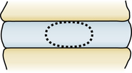
The vertebral bodies are separated at each level by the intervertebral disc. This viscoelastic structure is made up of a central nucleus pulposus, peripheral anulus fibrosus, and cartilaginous end plate of the disc, which separates it from the vertebral bodies above and below. Viscoelasticity is defined as a property of a material that exhibits both viscous and elastic characteristics when undergoing deformation. The material then has different mechanical properties that vary depending on the different loading rates. That is, if a load is applied slowly, the disc can respond with greater deformation, whereas if a load is applied rapidly, less deformation occurs. This property also changes as people age; with increasing age, there is a corresponding decrease in the ability of the disc to deform. There are 23 intervertebral discs starting between C2 and C3 and ending at L5 and S1. They make up 20% to 33% of the total height of the vertebral column, and there are regional differences that seem to parallel those of the vertebrae. The cross-sectional area of the discs increases in the rostrocaudal direction.
The central nucleus pulposus is composed of mucopolysaccharides and mucoprotein, forming a gel with water content ranging from 70% to 90%.1 The water content is highest at birth and decreases with age.18 The nucleus pulposus makes up approximately 30% to 50% of the cross-sectional area of the disc, and it seems to lie more posterior in the lumbar spine at the junction of the middle and posterior thirds of the disc in the sagittal plane.1 The viscoelastic properties of the nucleus pulposus allow it to act as an effective shock absorber for the spine. Surrounding the nucleus pulposus is the anulus fibrosus, which is made up of collagenous fibers in concentric laminated bands, with each band oriented 90 degrees to the adjacent bands and 30 degrees to the disc plane (Fig. 136-5). The inner fibers of the anulus are attached to the cartilaginous end plates, and the outermost fibers, known as Sharpey fibers, are attached to the cortical bone of the vertebral body. Because of the orientation of the fibers, the intervertebral disc effectively resists rotational, tensile, and shear stresses. The anulus does not resist compressive forces.
Facet Joints
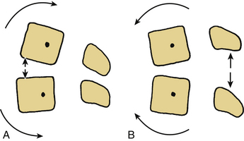
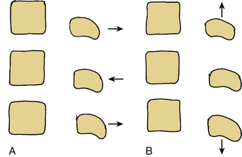
The vertebrae articulate with each other at the superior and inferior facet joints, which are diarthrodial joints with a loose synovial capsule located at the superior and inferior aspect of the pars interarticularis. In the cervical spine, the facet joints are oriented with an inclination of approximately 45 degrees from the horizontal, and this orientation changes in the thoracic and lumbar spine as the facets become larger and more vertical.1 The shape, position, and orientation of these articulating surfaces largely determine the pattern of movements throughout the spine (Fig. 136-6). The cervical spine from C2 to C7 allows 8 to 12 degrees of rotation, whereas the entire lumbar spine only allows 2 to 5 degrees.
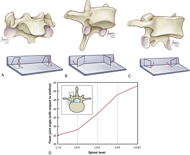
The coronally oriented cervical facet joints allow for supple flexion, extension, rotation, and lateral bending. In the thoracic spine, the inclination of the articulating surfaces is approximately 60 degrees, with an additional rotation about the y-axis of approximately 20 degrees toward the midline. This allows for limited flexion and extension but limits rotation. The facet surfaces in the lumbar spine are at an inclination of approximately 90 degrees, with approximately 45 degrees of rotation about the y-axis directed outward. This orientation allows for restricted rotation with greater flexion and extension. The orientations of the facet joints have a great deal of variation even within the specific regions of the spine.1 The facets act as important stabilizing structures in the spine, with resultant instability following unilateral or bilateral excision.19
In the lumbar spine, the sagittal orientation of the facet joints allows for substantial resistance to rotation, which is well documented.19–21 As the facet orientation begins to change from about T7 to L4, the torsional stiffness of the spine increases due to these changes in facet articulation, with the peak at T12-L1.22 In the cervical spine, transection of the disc and longitudinal ligaments resulted in a 33% increase in horizontal translation with flexion. This increased by 140% following transection of the facets.23 Removal of thoracic facets resulted in increased flexion and extension in the upper thoracic region and increased axial rotation in the lower thoracic–thoracolumbar region. The capsular ligaments also have a role in maintaining torsional strength.
The facets provide a load-bearing role when the spine is in extension. In dynamic studies with cadaver spines in various postures, the facets have been shown to carry anywhere from 0% to 33% of the load, depending on the force vector and position of the spine.24
Dorsal Elements
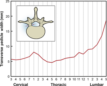
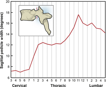
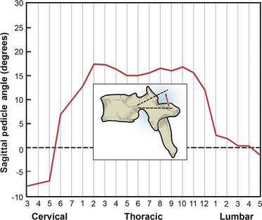
The remainder of the dorsal elements of the spine includes the pedicle, the lamina, the transverse processes, and the spinous process. Each of these elements varies significantly in morphology between regions of the spine. The pedicle serves as the bridge between the posterior elements and the vertebral body. The importance of pedicle anatomy is due to the major role pedicles now play in stabilization constructs. In the cervical spine, the pedicles are shorter with greater diameter. From the cervical to midthoracic region, the transverse pedicle width gradually decreases, and it then increases from the midthoracic to the lumbar region (Fig. 136-7).25–27 Sagittal pedicle width increases from the cervical to the thoracolumbar region and then decreases in the lumbar region (Fig. 136-8).25–27
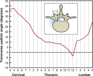
From the cervical to the thoracolumbar region, the transverse pedicle angle decreases, and it increases into the lumbar region (Fig. 136-9).25–27 The sagittal pedicle angle is a final consideration with regard to pedicle anatomy; it becomes fairly steep in the thoracic and thoracolumbar regions (Fig. 136-10).25–27
The laminae form the dorsal aspect of the neural canal, which contains the spinal cord. They extend from the pedicles to the spinous process dorsally and form the foundation for the spinous processes, provide dorsal protection to the dural sac, and serve as the attachment site for one of the seven spinal ligaments, the ligamentum flavum.2
The spinous processes project dorsally and, for the most part, caudally. They form attachment sites for the interspinous ligaments and supraspinous ligaments. The spinous processes project more caudally as one descends to the midthoracic spine. In the thoracolumbar and lumbar regions, the spinous processes also project more dorsally.2
The transverse processes of the midthoracic and lumbar spine are sizable enough to serve as sites for hook placement and fusion, but they are limited by a poor blood supply and are easily fractured.2
Ligaments
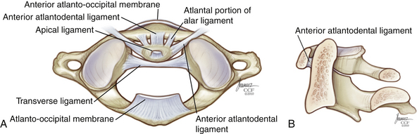
The ligamentous complex from the occiput to C2 represents a continuation of ligaments of the subaxial spine (Figs. 136-11 and 136-12). The anterior longitudinal ligament begins at the occiput as the atlanto-occipital membrane, as it passes between the occiput and the anterior arch of C1. The posterior atlanto-occipital membrane passes from the posterior arch of C1 to the occiput. When intact, these ligaments offer some advantage in preventing anterior displacement of C1 on C2. The apical ligament stretches from the tip of the odontoid process of C2 to the basion of the skull. The alar ligaments run obliquely from the rostrolateral aspect of the odontoid to the occipital condyles. The cruciate ligament has a vertical and transverse portion. The transverse portion of the ligament attaches to the tubercles located at the lateral masses of C1 and runs dorsal to the dens. The vertical portion of the cruciate ligament attaches to the occiput immediately dorsal to the apical ligament and descends to intertwine with the transverse portion. The vertical portion then descends to attach to the dorsocaudal aspect of C2. The transverse ligament is the most important ligament of the occipitocervical complex because it prevents horizontal translation of C1 on C2. The tectorial membrane is a continuation of the posterior longitudinal ligament and runs from the body of C2 over the posterior portion of the dens to attach to the anterior foramen magnum (see Fig. 136-11).
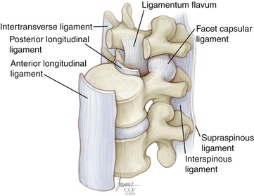
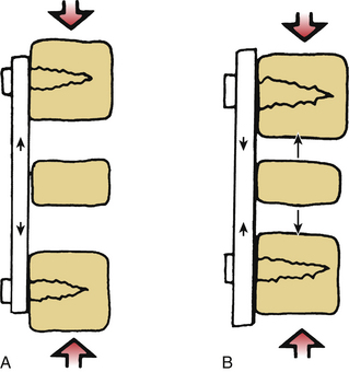
Beyond the occiput-C1-C2 complex, there are seven major spinal ligaments that work to stabilize the subaxial spine in its physiologic range of motion. These ligaments also work to restrict the motion of the spine to well-defined limits while at the same time allowing adequate motion and fixed postures to protect the spinal cord. Starting anteriorly and moving posteriorly, the ligaments are the anterior longitudinal ligament, posterior longitudinal ligament, capsular ligaments, intertransverse process ligaments, ligamentum flavum, interspinous ligament, and supraspinous ligament (see Fig. 136-12). The strength characteristics of the ligaments vary, and the effectiveness of a ligament not only depends on the morphology but also on the length of the moment arm through which it works28 (Fig. 136-13). A longer moment arm gives a relatively weak ligament a mechanical advantage so that it may contribute more to overall spinal stability.
The capsular ligaments are located at the facet joints. These fibers attach to the superior and inferior facets of adjacent vertebrae, and they act as significant stabilizers of the spine, particularly in the cervical spine. The fibers of the facet capsules run in a direction that is perpendicular to the plane of the facet joint. The moment arm (see Fig. 136-13) is not substantial, but the ligaments are strong enough for the stresses placed on them, which consist mainly of axial rotation, ventral shear loads, and axial loads under certain conditions. Other capsular ligaments in the thoracic spine attach the ribs to the vertebral bodies. These costochondral ligaments provide additional stability to the thoracic spine.
The ligamentum flavum has the highest percentage of elastic fibers of any tissue in the body. The ligamentum flavum is actually a pair of broad ligaments that connect the spinal laminae. They arise from the ventral surface of the caudal lamina and attach to the dorsal border of the adjacent rostral lamina, and they extend laterally to become confluent with the joint capsules. These ligaments begin at C1-2 and continue caudally to L5-S1. White and Panjabi noted that the ligament is in a state of resting “pretension” or tension, which is present with the spine in neutral position.1 This is postulated to stabilize the spine by keeping the intervertebral discs under compression and keeping the ligament from impinging on the spinal cord when the spine is in extension.
The interspinous and supraspinous ligaments connect the adjacent spinous processes. The interspinous ligament extends from the base to the tip of each spinous process, and this ligament is present from C2 to S1. The supraspinous ligament begins at the dorsal aspect of C7, attaching to the tip of the spinous process, and extends to the lumbosacral region. It is thought to be a continuation of the ligamentum nuchae associated with the dorsal cervical spine. These ligaments use the long moment arm of the spinous process to provide an effective resistance to flexion (see Fig. 136-13). These ligaments are extremely important in determining the stability of the spine, both for their importance in providing stability and for their inability to heal effectively.
Application of Basic Principles to Instrumentation
Implant Properties
Implants can be made of various materials, including metals, nonmetals (i.e., ceramic, glass), and bone. Each material has intrinsic properties that make it more useful for certain operations, and these specific properties must be kept in mind. An instrumented fusion is essentially a race between fusion formation and instrument failure, and, therefore, certain implants are more suited for this. Metallurgists have produced many alloys, which are now being used clinically in spinal implants.2 Stainless steel alloys include 316L stainless steel and 22-13-5 stainless steel, which has the same modulus of elasticity and tensile strength as 316L but twice the ultimate tensile strength.6 Titanium is available in pure, unalloyed forms, as well as various alloyed forms.
Pure titanium occurs in several grades (1–4) based on purity and degree of contaminants, and as the oxygen content increases, so does the strength of titanium.2 The modulus of elasticity remains unaltered, but the ultimate strength and 0.2% tensile strength (stress that causes 0.2% deformation) increase with the grade.29 Titanium has several advantages over other metals. Its modulus is very similar to bone, allowing for easy incorporation and limiting stress shielding.2,30,31 In addition, it also is resistant to glycocalyx formation, which may prevent latent infections.32 However, it is notch sensitive. This refers to the early fatigue failure of titanium with the addition of a notch or defect in its surface.29 Care must be taken when bending these materials. Titanium may also be alloyed with other elements such as aluminum, vanadium, niobium, and zirconium in specific concentrations, resulting in specific properties such as increased resistance to wear.2 The stainless steel alloys 316L and 22-13-5 are stiffer than titanium, resulting in a smaller transfer of stress from the implant to the bone, termed stress shielding. Cobalt chrome is now being used for spinal applications. It has the advantage of the imaging characteristics of titanium with the strength of stainless steel. Elements such as chromium and molybdenum present in these alloys provide resistance to corrosion.2
Deformability and the ability to resist fatigue are important characteristics of spinal implants. Implants do not fail because a static load exceeds the ultimate strength of the implant; they fail because of cyclical loading and fatigue. Fatigue refers to the cumulative damage of cyclical loading that occurs in the form of cracks and corrosion. Titanium performs better than steel at lower frequencies of loading.33
Other implant materials include synthetic nonmetals such as polymethylmethacrylate (PMMA), acrylics, ceramics, and glasses. PMMA is most commonly used but only in very specific situations. It has a high modulus of elasticity and is, therefore, very brittle. It has been shown that wire reinforcement, especially with the cobalt alloy Vitallium, yields a stronger construct.34
Finally, bone is commonly used as an implant. Bone graft harvested from the patient (i.e., fibula, iliac crest) is termed an autologous graft, whereas bone graft harvested from a cadaver is termed an allograft. It can be harvested as a strut graft with both cortical and cancellous bone, which can be cut and shaped to fit into a disc space or vertebrectomy cavity. Morselized bone chips may also be processed from cadavers and used as a graft extender. Bone is used to create a fusion, which ultimately lends stability to the spine, and instrumentation will ultimately fail unless fusion and stability are achieved.2 Bone can be placed ventrally or dorsally in the spine to create a fusion. Ventrally, a bone graft is placed in the weight-bearing part of the spine as an interbody graft, which results in compression and load sharing by the graft. This leads to faster and better healing as dictated by Wolff’s law. Wolff explained that internal and external changes in bone architecture occurred according to mathematical laws along with functional changes of bone.2,3 It has also been shown that electrophysiologic changes occur when bone is placed under compression (i.e., a negative charge is generated).35 Dorsally, bone is not exposed to the same fusion-enhancing forces as ventral weight-bearing grafts. The healing and fusion rates in dorsal fusions are less than in ventral fusions, probably because there is no compression that seems to encourage ventral, interbody fusion.2,36 The dorsal fusion mass will diminish in volume with time, and it has been shown that a larger volume of initial graft is required for a larger fusion mass at 18 months.37
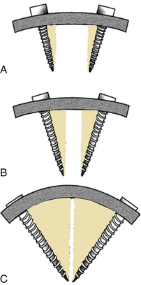
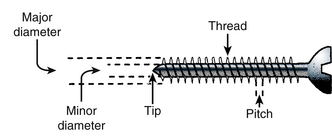
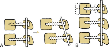
The interface between the implant and bone is important in ensuring stability. There are several ways in which implants and bone contact each other. According to Benzel,2 these are (1) abutting, (2) penetrating, (3) gripping, (4) conforming, and (5) osseointegration. Abutting implants typically include the interbody bone. The role of the interbody implant is to resist axial loads, and this is done most effectively through a large surface area contact between the ends of the bone graft and the adjacent vertebral bodies. Placement of the graft in the IAR is ideal for resisting axial loads, and placement ventral to the IAR results in a moment arm and some degree of distraction.2 Penetrating implants include nails, screws, and spikes. The role of the penetrating implant is that of an anchor, and important considerations with regard to these implants include pullout resistance and overall strength when they function as fixed-arm cantilevers.2 Pullout resistance of screws is enhanced by engaging cortical bone, which markedly resists pullout, and through triangulation (Fig. 136-14) or placement of converging or diverging screws optimally at 90 degrees to one another.38 As discussed previously, the bending strength is proportional to the cube of the inner diameter of the screw (section modulus). The outer diameter and thread depth are important in pullout resistance (Fig. 136-15). Hooks and wires are examples of the gripping implants. Wire may be looped around the laminae and spinous processes of adjacent vertebrae and secured via twisting the loops together, and hooks may be placed at the laminae, pedicles, or transverse processes to augment dorsal instrumentation, especially screws placed in osteoporotic bone.2 They contact cortical bone over a greater surface area, and thus may perform better in the setting of osteoporotic bone. Hooks may also be used to augment screw pullout resistance within the same construct.2 Conforming implants have been mentioned briefly and at this point include PMMA and acrylics. These implants have the unique property of conforming to surrounding bone and are used by some surgeons to augment the screw-bone interface.39–41 The bonding of bone to nonbiologic material is known as osseointegration, and when this occurs, the load transfer from implant to bone is distributed over a much larger surface area, reducing stress risers (focal concentrations of stress).2 Titanium and a titanium alloy, Ti-13Nb-13Zr (niobium, zirconium), have exhibited potential for osseointegration.2,30,31
Application to Implants
Spinal implants impart complex forces on the spine that can be broken down into basic component vectors and that may be considered separately. Rarely is any one force applied in isolation, and spinal implants function through several of the basic mechanisms of force application. Benzel lists six basic mechanisms of force application: (1) simple distraction, (2) three-point bending, (3) tension-band fixation, (4) fixed moment arm cantilever, (5) nonfixed moment arm cantilever, and (6) applied moment arm cantilever.2 These represent the basic mechanisms by which implants impart force to the spine, and a single implant often functions using several mechanisms at once.
Anterior spine surgery frequently incorporates simple distraction and tension band fixation through a nonfixed moment arm cantilever fixation. Three-point bending is also used in longer constructs to stabilize the plate and prevent translation. Because surgery in the anterior spine is located ventral to the IAR, a bending moment is applied to the instrumented segments. Simple distraction may be applied through ventral placement of an interbody graft (ventral to the neutral axis/IAR) or by placement of a fixed moment arm cantilever in the form of a plate and screws. Plates secured to the anterior spine by screws in distraction are more frequently applied in the cervical spine. Placement of ventral distraction results in extension of the spine, and implants placed in this manner resist axial loads (Fig. 136-16). Placement of an anterior graft allows for distraction of the vertebral bodies, although the graft is left in compression. Typically isolated distraction of implants is avoided because this places the implant in a load-bearing rather than load-sharing mode. These implants bear much of the axial load; thus, failure may occur typically at the screw-plate interface. These same implants resist extension of the spine, and, therefore, act as tension band fixators when the spine is placed in extension. Distraction and compression are forces applied perpendicular to IAR resulting in torque (Fig. 136-17). Three-point bending is applied parallel to the IAR and often is accompanied by distraction or compression forces2 (Fig. 136-18). Three-point bending occurs when a fulcrum directs a force vector in a direction opposite to the two terminal force vectors. The force at the fulcrum is equal to the sum of the terminal forces.2
Three-point bending requires an intermediate point of fixation between the terminal points of fixation, and when used in a ventral construct will resist translational deformation (Fig. 136-19). Ventral compressive implants do not resist axial loads, and the axial load-resisting ability of the spine must be intact or augmented (usually by an interbody graft) when these implants are used. Dynamic ventral systems allow controlled subsidence and therefore enhanced load sharing by the spine to augment bone healing and fusion of interbody grafts in the cervical spine.
Interbody grafts may be placed in the neutral axis of the spine or the IAR. These implants include autologous bone (i.e., rib, fibula, iliac crest), allograft, acrylic and wire constructs, and cages filled with morselized bone. These implants are usually placed to restore the axial load-bearing ability of the spine, and the principal forces are distraction and compression. Removal of a vertebral body (i.e., spondylectomy) or removal of a disc (i.e., discectomy), which incorporates the neutral or weight-bearing axis of the spine, usually requires placement of a graft to restore stability. There are several important considerations in placing interbody grafts. Migration of the bone graft into the adjacent vertebral body is known as subsidence. This can be avoided by ensuring that the abutting interbody graft occupies a large surface area and is able to withstand axial loads (Fig. 136-20). The cortical end plates of the vertebral body may be left intact to protect against subsidence as well. The cortical margins of the vertebral body are good buttresses for instrumentation and interbody grafts. Stress shielding occurs when the implant bears more of the axial load than the interbody graft, reducing compressive forces and the chance for fusion by increasing bone resorption. Stress shielding is avoided by placing the interbody graft under compression to incorporate load-sharing principles, which can be achieved by ventral tension band fixation. A final important consideration with regard to interbody grafts is that intact surrounding ligaments add stability when a graft that is sufficiently large is placed to distract the end plates and therefore ligaments are placed under tension.
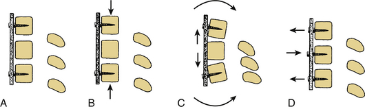
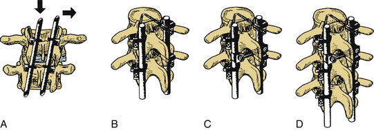
Dorsal instrumentation incorporates distraction, tension band fixation, and three-point bending to reduce and stabilize the spine. Often dorsal instrumentation accompanies ventral instrumentation to augment the stability of the spine, especially in flexion. This is an important concept. Dorsal instrumentation must be very rigid and is load bearing in dorsal-only constructs. This consideration is critical when determining the need for additional fixation and the levels of fixation. Loss of anterior column support (i.e., fracture) leads to implant failure unless the anterior support is restored, or longer, more biomechanically rigid instrumentation is used.5 The implants act as a cantilever beam in these dorsal-only constructs. Dorsal fixation techniques are numerous and include wires, hooks, screws, and rods. Cross fixation may be added to stabilize the construct and prevent a coronal or sagittal parallelogram deformity (Fig. 136-21). Dorsal tension band fixation can be accomplished with laminar wires, clamps, springs, and rigid constructs consisting of lateral mass screws and rods in the cervical spine and pedicle screws, rods, laminar wires, hooks, and cross fixators in the thoracic and lumbar spine. Isolated dorsal compressive constructs are rare. Instrumentation over a number of segments often uses intermediate points of fixation and three-point bending to resist translational deformity (Fig. 136-22). Multisegmented instrumentation ensures that the load is distributed over a number of segments. Intact anatomy can be exploited such as in the cervical spine. Dorsal tension band fixation with engagement of the facets results in increased translational stability. At the same time, fusion of the cervical spine can be achieved ventrally and augmented by disruption of the facet joint and subsequent fusion of the lateral masses. As previously stated, axial load bearing by the facet joints is increased when the cervical spine is extended and the joints are engaged. The orientation of the facets resists translational deformity as well.
Pedicle screws are better able to control the vertebral body by virtue of the improved fixation. Often, the pedicle screw is at or beyond the IAR, giving it excellent three-dimensional control of the vertebral body. In this way, surgeons are able to perform derotation procedures in complex deformity cases and push the vertebral body to a more desirable position. Pedicle screws, however, are not the “be all and end all.” Careful attention to spinal alignment and balance must be taken into account. The spine must be reduced properly, and the SVA must be returned to within 2 cm, to prevent increased stress on the vertebral levels. If residual imbalance remains, this may lead to pseudarthrosis42 and worse clinical outcomes.8,43 Patient factors are also critical; osteoporosis and obesity may also play a role in adjacent-level disease or fracture.44 Often, posterior osteotomies must be performed, with or without anterior support, to shorten the posterior column and pull the spine to a more neutral alignment. In this way, the spinal instruments can change from load bearing to load shearing and support the spine while the fusion occurs.
Long moment arms may also play a role in adjacent-level degeneration and fracture. After long fusions, the fused spine imparts increased biomechanical loads to the adjacent segments. Long, rigid fusion constructs do not allow for adequate posterior elongation or stress dissipation; thus, the stress may be transferred to adjacent segments. This is particularly true at the distal segments. Several authors have advocated against long fusions ending at the L5 level, due to high revision rates at the L5-S1 disc.45–48 They noted high rates of degeneration and revision of that level. Additionally, for fusions to the sacrum, most authors recommend iliac fixation to prevent distal failure or sacral fracture.49 The L5-S1 level, due to the high stress, is also the most likely level for pseudarthrosis. This can be prevented with iliac fixation and/or interbody grafting for structural anterior support.50,51
Benzel E.C. Biomechanics of spine stabilization. Rolling Meadows, IL, 2001 American Association of Neurological Surgeons. 2001:1-19.
Glassman S.D., Bridwell K., Dimar J.R., et al. The impact of positive sagittal balance in adult spinal deformity. Spine (Phila Pa 1976). 2005;30(18):2024-2029.
Kim Y.J., Bridwell K.H., Lenke L.G., et al. Pseudarthrosis in long adult spinal deformity instrumentation and fusion to the sacrum: prevalence and risk factor analysis of 144 cases. Spine (Phila Pa 1976). 2006;31(20):2329-2336.
Kostuik J.P., Valdevit A., Chang H.G., et al. Biomechanical testing of the lumbosacral spine. Spine (Phila Pa 1976). 1998;23(16):1721-1728.
White A.A., Panjabi M.M. Clinical biomechanics of the spine, ed 2. Philadelphia: Lippincott Williams & Wilkins; 1990. pp 1–125
1. White A.A., Panjabi M.M. Clinical biomechanics of the spine, ed 2. Philadelphia: Lippincott Williams & Wilkins; 1990. pp 1–125
2. Benzel E.C. Biomechanics of spine stabilization. Rolling Meadows, IL: American Association of Neurological Surgeons; 2001. pp 1–19
3. Wolff J. Das Gesetz der Transformation der Knochen. Berlin: Hirschwald Verlag; 1892.
4. Chance C.Q. Note on a type of flexion fracture of the spine. Br J Radiol. 1948;21:452-453.
5. McCormack T., Karaikovic E., Gaines R.W. The load sharing classification of spine fractures. Spine (Phila Pa 1976). 1994;19(15):1741-1744.
6. Vaccaro A.R., Lehman R.A.Jr., Hurlbert R.J., et al. A new classification of thoracolumbar injuries: the importance of injury morphology, the integrity of the posterior ligamentous complex, and neurologic status. Spine (Phila Pa 1976). 2005;30(20):2325-2333.
7. Sim E., Vaccaro A.R., Berzlanovich A., et al. In vitro genesis of subaxial cervical unilateral facet dislocations through sequential soft tissue ablation. Spine (Phila Pa 1976). 2001;26(12):1317-2339.
8. Glassman S.D., Bridwell K., Dimar J.R., et al. The impact of positive sagittal balance in adult spinal deformity. Spine. 2005;30(18):2024-2029.
9. Schlenk R.P., Kowalski R.J., Benzel E.C. Biomechanics of spinal deformity. Neurosurg Focus. 14(1), 2003.
10. Lafage V., Schwab F., Skalli W., et al. Standing balance and sagittal plane spinal deformity: analysis of spinopelvic and gravity line parameters. Spine (Phila Pa 1976). 2008;33(14):1572-1578.
11. Hansson T.H., Keller T.S., Panjabi M.M. A study of the compressive properties of lumbar vertebral trabeculae: effects of tissue characteristics. Spine (Phila Pa 1976). 1987;12:56-62.
12. Lindahl O. Mechanical properties of dried defatted spongy bone. Acta Orthop Scand. 1976;47:11-19.
13. McBroom R.J., Hayes W.C., Edwards W.T., et al. Prediction of vertebral body compressive fracture using quantitative computed tomography. J Bone Joint Surg [Am]. 1985;67(8):1206-1214.
14. Rockoff S.D., Sweet E., Bleustein J. The relative contribution of trabecular and cortical bone to the strength of human lumbar vertebrae. Calcif Tissue Res. 1965;3:163-175.
15. Bell G.H., Dunbar O., Beck J.S., Gibb A. Variation in strength of vertebrae with age and their relation to osteoporosis. Calcif Tissue Res. 1967;1:75-86.
16. Perry O. Fracture of the vertebral end-plate in the lumbar spine. Acta Orthop Scand. 1957;25(Suppl):157-165.
17. Kumar A., Kozak J.A., Doherty B.J., Dickson J.H. Interspace distraction and graft subsidence after anterior lumbar fusion with femoral strut allograft. Spine (Phila Pa 1976). 1993;18:2393-2400.
18. Panagiotacopulos N.D., Pope M.G., Block R., Krag M.H. Water content in human intervertebral discs. Part II. Viscoelastic behavior. Spine (Phila Pa 1976). 1987;12:918-924.
19. Abumi K., Panjabi M.M., Duranceau J.S., Kramer K. Instabilities due to partial and total facetectomies of the lumbar spine. Presented at the 34th annual meeting of the Orthopedic Research Society. Atlanta. 1988.
20. Adams M.A., Hutton W.C. The mechanical function of the lumbar apophyseal joints. Spine (Phila Pa 1976). 1983;8(3):327-330.
21. Adams M.A., Hutton W.C. The relevance of torsion to the mechanical derangement of the lumbar spine. Spine (Phila Pa 1976). 1981;6:241-248.
22. Markolf K.L. Deformation of the thoracolumbar intervertebral joint in response to external loads: a biomechanical study using autopsy material. J Bone Joint Surg [Am]. 1972;54(3):511-533.
23. Panjabi M.M., White A.A., Johnson R.M. Cervical spine mechanics as a function of transaction of components. J Biomech. 1975;8:327-336.
24. King A.I., Prasad P., Ewing C.L. Mechanism of spinal injury due to caudocephalad acceleration. Orthop Clin North Am. 1975;6:19-31.
25. Krag M.G., Weaver D.L. Morphometry of the thoracic and lumbar spine related to transpedicular screw placement for surgical and spinal fixation. Spine (Phila Pa 1976). 1988;13:27-32.
26. Panjabi M.M., Duranceau J., Goel V., et al. Cervical human vertebrae: quantitative three-dimensional anatomy of the middle and lower regions. Spine (Phila Pa 1976). 1991;16:861-869.
27. Zindrick M.R., Wiltse L.L., Doornik A., et al. Analysis of the morphometric characteristics of the thoracic and lumbar pedicles. Spine (Phila Pa 1976). 1987;12:160-166.
28. Panjabi M.M., Greenstein G., Crisco J.J.III. Three-dimensional quantitative morphology of lumbar spinal ligaments. J Spinal Disord. 1991;4:54-72.
29. Dick J.C., Bourgeault C.A. Notch sensitivity of titanium alloy, commercially pure titanium, and stainless steel spinal implants. Spine (Phila Pa 1976). 2001;26(15):1668-1672.
30. Goodman S.B., Davidson J.A., Fornasier V.L., et al. Histological response to cylinders of a low-modulus titanium alloy (Ti-13Nb-13Zr) and a wear-resistant zirconium alloy (Zr-2.5Nb) implanted in the rabbit tibia. J Appl Biomater. 1993;4:331-339.
31. Mishra A.K., Bucknell A.L., et al. In vivo study of anodized commercially pure titanium and diffusion hardened Ti13Nb-13Zr bone plates in a goat model. Toronto: Proceedings of the Fifth World Biomaterials Congress; June, 1996. pp ii–797
32. Emery B.E., Dixit R., Formby C.C., Biedlingmaier J.F. The resistance of maxillofacial reconstruction plates to biofilm formation in vitro. Laryngoscope. 2003;113(11):1977-1982.
33. Stambough J.L., Genaidy A.F., Huston R.L., et al. Biomechanical assessment of titanium and stainless steel posterior spinal constructs: effects of absolute/relative loading and frequency on fatigue life and determination of failure modes. J Spine Disord. 1997;10:473-481.
34. Taitsman J.P., Saha S. Tensile strength of wire-reinforced bone cement and twisted stainless-steel wire. J Bone Joint Surg [Am]. 1977;59:419-425.
35. Yasuda I., Noguchi K., Sata T., et al. Dynamic callus and electrical callus. J Bone Joint Surg [Am]. 1955;37:1292-1293.
36. Egger E.L., Gottsauner-Wolf F., Palmer J., et al. Effects of axial dynamization on bone healing. J Trauma. 1993;34:185-192.
37. Kim K.W., Ha K.Y., Moon M.S., et al. Volumetric change of the graft bone after intertransverse fusion. Spine (Phila Pa 1976). 1999;24:428-433.
38. Benzel E.C., Baldwin N.G. Crossed-screw fixation of the unstable thoracic and lumbar spine. J Neurosurg. 1995;83:11-16.
39. Burval D.J., McLain R.F., Milks R., Inceoglu S. Primary pedicle screw augmentation in osteoporotic lumbar vertebrae: biomechanical analysis of pedicle fixation strength. Spine (Phila Pa 1976). 2007;32(10):1077-1083.
40. Duff T.A. Surgical stabilization of traumatic cervical spine dislocation using methylmethacrylate. J Neurosurg. 1986;64:39-44.
41. Panjabi M.M., Hopper W., White III, et al. Posterior spine stabilization with methylmethacrylate: biomechanical cement and wire: a clinical review. J Neurosurg. 1988;68:576-584.
42. Kim Y.J., Bridwell K.H., Lenke L.G., et al. Pseudarthrosis in long adult spinal deformity instrumentation and fusion to the sacrum: prevalence and risk factor analysis of 144 cases. Spine (Phila Pa 1976). 2006;31(20):2329-2336.
43. Djurasovic M., Glassman S.D. Correlation of radiographic and clinical findings in spinal deformities. Neurosurg Clin North Am. 2007;18(2):223-237.
44. Kim Y.J., Bridwell K.H., Lenke L.G., et al. Proximal junctional kyphosis in adult spinal deformity after segmental posterior spinal instrumentation and fusion: minimum five-year follow-up. Spine (Phila Pa 1976). 2008;33(20):2179-2184.
45. Disch A.C., Schmoelz W., Matziolis G., et al. Higher risk of adjacent segment degeneration after floating fusions: long-term outcome after low lumbar spine fusions. J Spinal Disord Tech. 2008;21(2):79-85.
46. Edwards C.C.II, Bridwell K.H., Patel A., et al. Thoracolumbar deformity arthrodesis to L5 in adults: the fate of the L5-S1 disc. Spine (Phila Pa 1976). 2003;28(18):2122-2131.
47. Kuhns C.A., Bridwell K.H., Lenke L.G., et al. Thoracolumbar deformity arthrodesis stopping at L5: fate of the L5-S1 disc, minimum 5-year follow-up. Spine (Phila Pa 1976). 2007;32(24):2771-2776.
48. Tsuchiya K., Bridwell K.H., Kuklo T.R., et al. Minimum 5-year analysis of L5-S1 fusion using sacropelvic fixation (bilateral S1 and iliac screws) for spinal deformity. Spine (Phila Pa 1976). 2006;31(3):303-308.
49. Klineberg E., McHenry T., Bellabarba C., et al. Sacral insufficiency fractures caudal to instrumented posterior lumbosacral arthrodesis. Spine (Phila Pa 1976). 2008;33(16):1806-1811.
50. Kostuik J.P., Valdevit A., Chang H.G., et al. Biomechanical testing of the lumbosacral spine. Spine (Phila Pa 1976). 1998;23(16):1721-1728.
51. Weistroffer J.K., Perra J.H., Lonstein J.E., et al. Complications in long fusions to the sacrum for adult scoliosis: minimum five-year analysis of fifty patients. Spine (Phila Pa 1976). 2008;33(13):1478-1483.