Axial Skeleton
Osteology and Arthrology
REGIONAL ANATOMY AND KINEMATICS ACROSS THE VERTEBRAL COLUMN
SUMMARY OF THE KINEMATICS WITHIN THE VERTEBRAL COLUMN
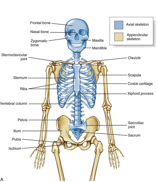
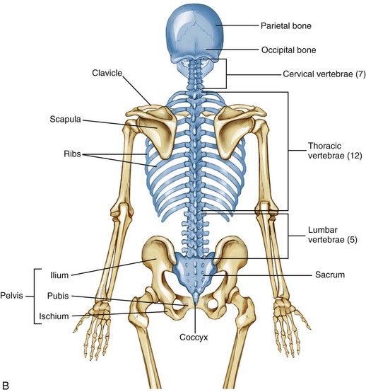
The skeleton as a whole is divided into the axial skeleton and the appendicular skeleton. The appendicular skeleton consists of the bones of the extremities, including the clavicle, scapula, and pelvis; the axial skeleton, in contrast, consists of the cranium, vertebral column (spine), ribs, and sternum (Figure 9-1). As indicated in Figure 9-1, A, the axial and appendicular skeletons are joined by the sternoclavicular joints superiorly and the sacroiliac joints inferiorly.
The osteology and associated arthrology presented in this chapter focus primarily on the axial skeleton. This focus includes the craniocervical region, vertebral column, and sacroiliac joints, describing how these articulations provide stability, movement, and load transfer throughout the axial skeleton. Muscles play a large role in this function and are the primary focus of Chapter 10.
Table 9-1 summarizes the terminology used to describe the relative location or region within the axial skeleton.
TABLE 9-1.
Terminology Describing Relative Location or Region within the Axial Skeleton
| Term | Synonym | Definition |
| Posterior | Dorsal | Back of the body |
| Anterior | Ventral | Front of the body |
| Medial | None | Midline of the body |
| Lateral | None | Away from the midline of the body |
| Superior | Cranial | Head or top of the body |
| Inferior | Caudal (the “tail”) | Tail, or the bottom of the body |
The definitions assume a person is in the anatomic position.
OSTEOLOGY
Components within the Axial Skeleton
CRANIUM
The cranium encases and protects the brain and several essential sensory organs (eyes, ears, nose, and vestibular system). Of the many individual bones of the cranium, only the temporal and occipital bones are relevant to the material covered in Chapters 9 and 10.
Temporal and Occipital Bones: Each of the two temporal bones forms part of the lateral external surface of the skull, immediately surrounding and including the external acoustic meatus (Figure 9-2). The mastoid process, an easily palpable structure, is just posterior to the ear. This prominent process serves as an attachment for many muscles, such as the sternocleidomastoid.
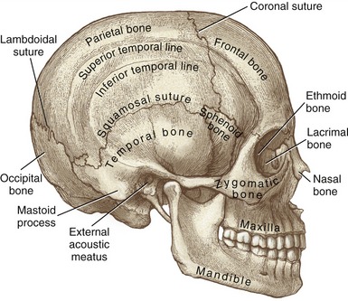
FIGURE 9-2. Lateral view of the skull.
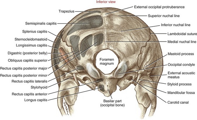
The occipital bone forms much of the posterior base of the skull (Figure 9-3). The external occipital protuberance is a palpable midline point, serving as an attachment for the ligamentum nuchae and the medial part of the upper trapezius muscle. The superior nuchal line extends laterally from the external occipital protuberance to the base of the mastoid process of the temporal bone. This thin but distinct line marks the attachments of several extensor muscles of the head and neck, such as the trapezius and splenius capitis muscles. The inferior nuchal line marks the anterior edge of the attachment of the semispinalis capitis muscle.
VERTEBRAE: BUILDING BLOCKS OF THE SPINE
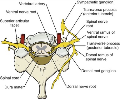
In addition to providing vertical stability throughout the trunk and neck, the vertebral column protects the spinal cord, ventral and dorsal nerve roots, and exiting spinal nerve roots (Figure 9-4). The relationship between the spinal cord and exiting nerve roots throughout the entire vertebral column is schematically shown in Figure III-1 in Appendix III, Part A.
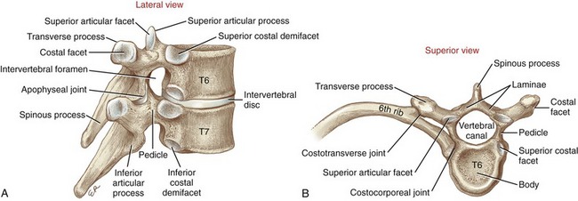
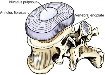
The midthoracic vertebrae demonstrate many of the essential anatomic and functional characteristics of any given vertebra (Figure 9-5). As a general orientation, a given vertebra can be subdivided into three sections. Anteriorly is the large vertebral body—the primary weight-bearing component of a vertebra. Posteriorly are the transverse and spinous processes, laminae, and articular processes, collectively referred to as posterior elements (also referred to as the “vertebral arch” or “neural arch”). The pedicles, the third section, act as bridges that connect the body with the posterior elements. Thick and strong, the pedicles transfer muscle forces applied to the posterior elements forward, for dispersion across the vertebral body and intervertebral discs. Table 9-2 provides greater details on the structure and function of the components of a typical midthoracic vertebra.
TABLE 9-2.
Major Parts of a Midthoracic Vertebra
| Part | Description | Primary Function |
| Body | Large cylindric mass of trabecular bone lined by a thin cortex of bone. The multidirectional trabecular core is lightweight while still offering excellent resistance against compression. | Primary weight-bearing structure of each vertebra. |
| Intervertebral disc | Thick ring of fibrocartilage between vertebral bodies of C2 and below. | Shock absorber and spacer throughout the vertebral column. |
| Interbody joint | A cartilaginous joint joint formed between the superior and inferior surfaces of an intervertebral disc and adjacent vertebral bodies. | Primary bond between vertebrae. |
| Pedicle | Short, thick dorsal projection of bone from the mid-to-superior part of the vertebral body. | Connects the vertebral body to the posterior elements of a vertebra. |
| Lamina | Thin vertical plate of bone connecting the base of the spinous process to each transverse process. (The term laminae refers to both right and left laminae.) | Protects the posterior aspect of the spinal cord. |
| Vertebral canal | Central canal located just posterior to the vertebral body. The canal is surrounded by the pedicles and laminae. | Houses and protects the spinal cord. |
| Intervertebral foramen | Lateral opening between adjacent vertebrae. | Passageway for spinal nerve roots exiting the vertebral canal. |
| Transverse process | Horizontal projection of bone from the junction of a lamina and a pedicle. | Attachments for muscles, ligaments, and ribs. |
| Costal facets (on body) | Rounded impressions formed on the lateral sides of the thoracic vertebral bodies. Most thoracic vertebral bodies have partial superior and inferior facets (called demifacets). | Attachment sites for the heads of ribs (costocorporeal joints). |
| Costal facets (on transverse process) | Oval facets located at the anterior tips of most thoracic transverse processes. | Attachment sites for the articular tubercle of ribs (costotransverse joints). |
| Spinous process | Dorsal midline projection of bone from the laminae. | Midline attachments for muscles and ligaments. |
| Superior and inferior articular processes, including articular facets and apophyseal joints | Paired vertical articular processes arising from the junction of a lamina and pedicle. Each process has smooth cartilage-lined articular facets. In general, superior articular facets face posteriorly, and inferior articular facets face anteriorly. | Superior and inferior articular facets form paired apophyseal joints. These synovial joints guide the direction and magnitude of intervertebral movement. |
RIBS
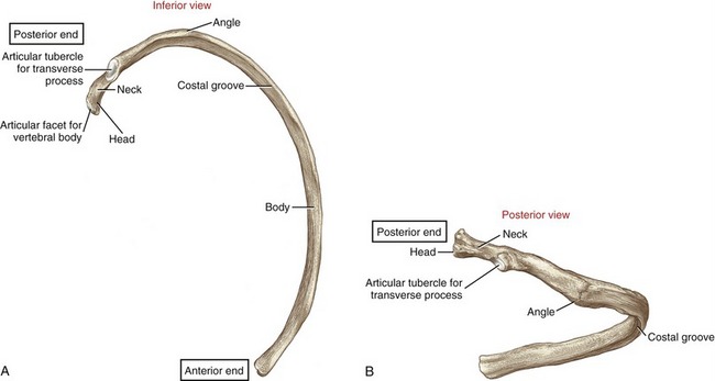
Twelve pairs of ribs enclose the thoracic cavity, forming a protective cage for the cardiopulmonary organs. The posterior end of a typical rib has a head, a neck, and an articular tubercle (Figure 9-6). The head and tubercle articulate with a thoracic vertebra, forming two synovial joints: costocorporeal (also called costovertebral) and costotransverse, respectively (see Figure 9-5, B).188 These joints anchor the posterior end of a rib to its corresponding vertebra. A typical costocorporeal joint connects the head of a rib to a pair of costal demifacets that span two adjacent vertebrae and the intervening intervertebral disc. A costotransverse joint connects the articular tubercle of a rib with a costal facet on the transverse process of a corresponding vertebra.
The anterior end of a rib consists of flattened hyaline cartilage. Ribs 1 through 10 attach either directly or indirectly to the sternum, thereby completing the thoracic rib cage anteriorly. The cartilage of ribs 1 to 7 attaches directly to the lateral border of the sternum via seven sternocostal joints (Figure 9-7). The cartilage of ribs 8 to 10 attaches to the sternum by fusing to the cartilage of the immediately superior rib. Ribs 11 and 12 do not attach to the sternum but are anchored by lateral abdominal muscles.
STERNUM
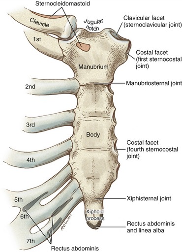
The sternum is slightly convex and rough anteriorly, and slightly concave and smooth posteriorly. The bone has three parts: the manubrium (Latin, meaning “handle”), the body, and the xiphoid process (from the Greek, “sword”) (see Figure 9-7). Developmentally, the manubrium fuses with the body of the sternum at the manubriosternal joint, a cartilaginous (synarthrodial) articulation that often ossifies later in life.188 Just lateral to the jugular notch of the manubrium are the clavicular facets of the sternoclavicular joints. Immediately inferior to the sternoclavicular joint is a costal facet that accepts the head of the first rib at the first sternocostal joint.
The lateral edge of the body of the sternum is marked by a series of costal facets that accept the cartilages of ribs 2 to 7. The arthrology of the sternocostal joints is discussed in greater detail in Chapter 11, within the context of ventilation. The xiphoid process is attached to the inferior end of the body of the sternum by the xiphisternal joint. Like the manubriosternal joint, the xiphisternal joint is connected primarily by fibrocartilage. The xiphisternal joint often ossifies by 40 years of age.188
Vertebral Column as a Whole
NORMAL CURVATURES WITHIN THE VERTEBRAL COLUMN
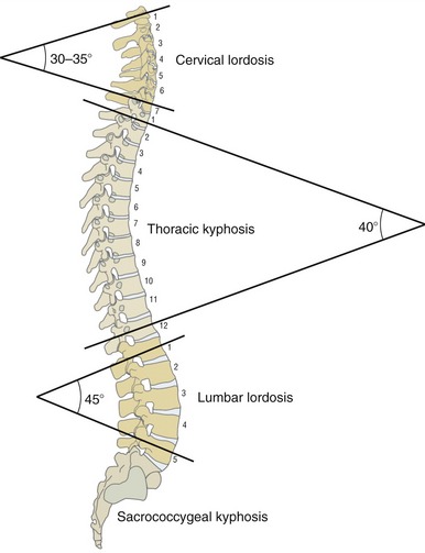
The human vertebral column consists of a series of reciprocal curvatures within the sagittal plane (Figure 9-8, A). These natural curvatures contribute to “ideal” spinal posture while one is standing. The curvatures also define the neutral position of the different regions of the spine. In the neutral (anatomic) position, the cervical and lumbar regions are naturally convex anteriorly and concave posteriorly, exhibiting an alignment called lordosis, meaning to “bend backward.” The degree of lordosis is usually less in the cervical region than in the lumbar region. The thoracic and sacrococcygeal regions, in contrast, exhibit a natural kyphosis. Kyphosis describes a curve that is concave anteriorly and convex posteriorly. The anterior concavity provides space for the organs within the thoracic and pelvic cavities.
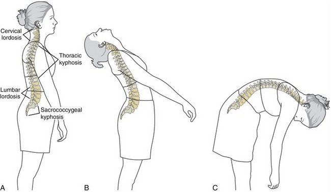
The natural curvatures within the vertebral column are not fixed but are dynamic and change shape during movements and adjustment of posture. Further extension of the vertebral column accentuates the cervical and lumbar lordosis but reduces the thoracic kyphosis (see Figure 9-8, B). In contrast, flexion of the vertebral column decreases, or flattens, the cervical and lumbar lordosis but accentuates the thoracic kyphosis (see Figure 9-8, C). In contrast, the sacrococcygeal curvature is fixed, being concave anteriorly and convex posteriorly.
LINE OF GRAVITY PASSING THROUGH THE BODY
Although highly variable, the line of gravity acting on a standing person with ideal posture passes near the mastoid process of the temporal bone, anterior to the second sacral vertebra, just posterior to the hip, and anterior to the knee and ankle (Figure 9-9). In the vertebral column, the line of gravity typically falls just to the concave side of the apex of each region’s curvature. Ideal posture therefore allows gravity to produce a torque that helps maintain the optimal shape of the spinal curvatures. The external torque attributed to gravity is greatest at the apex of each region: C4 and C5, T6, and L3.
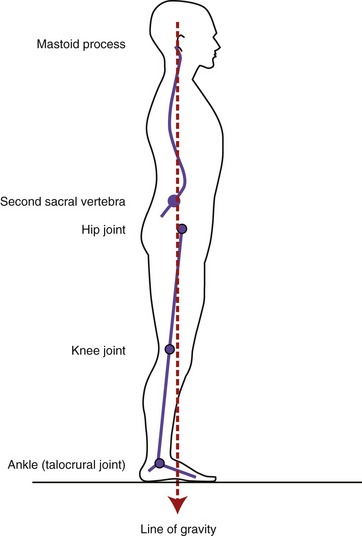
The image depicted in Figure 9-9 is more ideal than real because each person’s posture is unique and transient. Factors that alter the spatial relationship between the line of gravity and the spinal curvatures include fat deposition, the specific shapes of the regional spinal curvatures, static posturing of the head and the limbs, muscle strength, connective tissue extensibility, and the position and magnitude of loads supported by the body. The particular orientation of the line of gravity relative to the axial skeleton has important biomechanical consequences on the stress placed on the region. For example, gravity passing posterior to the lumbar region produces a constant extension torque on the low back, facilitating natural lordosis. Alternatively, gravity passing anterior to the lumbar region produces a constant flexion torque. In both cases the external torque created by the line of gravity (and its associated external moment arm) must be neutralized by forces and torques produced actively by muscle and passively by connective tissues. In extreme postures, these forces may be high; if prolonged, they may lead to undesirable postural compensations as well as structural changes, often associated with pain.
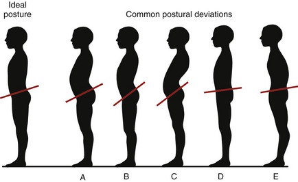
The normal sagittal plane alignment of the vertebral column may be altered by disease, such as ankylosing spondylosis, poliomyelitis, spinal cord injury, muscular dystrophy, or osteoporosis and muscle weakness associated with advanced age. Often, relatively minor forms of abnormal or deviated postures occur in otherwise healthy persons. As illustrated in Figure 9-10, excessive lumbar lordosis may develop as compensation for excessive thoracic kyphosis and vice versa. The “swayback” posture shown in Figure 9-10, C, for example, describes a combined exaggerated lumbar lordosis and thoracic kyphosis. Often, other unexplainable postures exist such as the “rounded back” appearance in Figure 9-10, E. This posture shows a combined excessive thoracic kyphosis with reduced lumbar lordosis. Regardless of the cause or location of the postural deviation, the associated abnormal curvatures alter the spatial relation between the line of gravity and each spinal region. When severe, abnormal vertebral curvatures increase stress on muscles, ligaments, bones, discs, apophyseal joints, and exiting spinal nerve roots. Abnormal curves also change the volume of body cavities. An exaggerated thoracic kyphosis, for example, can significantly reduce the space for the lungs to expand during deep breathing.
LIGAMENTOUS SUPPORT OF THE VERTEBRAL COLUMN
The vertebral column is supported by an extensive set of ligaments. Spinal ligaments limit motion, help maintain natural spinal curvatures, and, by stabilizing the spine, protect the delicate spinal cord and spinal nerve roots. These ligaments, described in the following paragraphs and illustrated in Figure 9-11, all possess slightly different strengths and functions depending on their locations within the vertebral column.85 The basic structure and generic function of each ligament are summarized in Table 9-3.
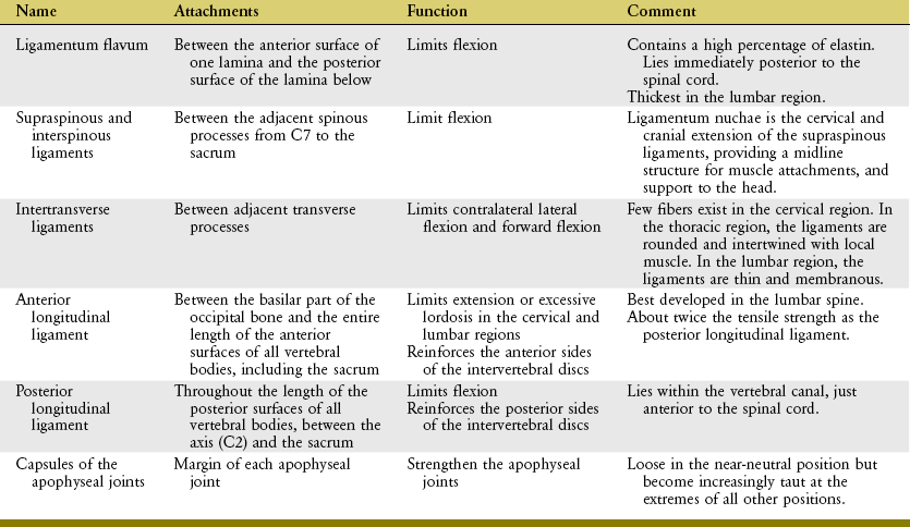
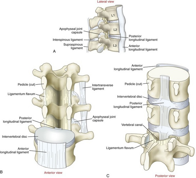
Ligamentum flavum literally means “yellow ligament,” reflecting its high content of light yellow elastic connective tissue. Histologically, the ligamentum flavum consists of about 80% elastin and 20% collagen.223 The tissue’s highly elastic nature is ideal for exerting a relatively constant, although modest, resistance throughout a wide range of flexion.85 Measurements have shown that between the neutral position and full flexion, the ligamentum flavum experiences an approximately 35% increase in strain (elongation) (Figure 9-12).139 Extreme and very forceful flexion beyond this length can ultimately lead to its rupture, possibly creating damaging compressive forces on the anterior side of the intervertebral disc.4 The ligamenta flava are thickest in the lumbar region,188 where the magnitude of intervertebral flexion is the largest of any region within the vertebral column.
The highly elastic nature of the ligamentum flavum is interesting from both a functional and a structural perspective. In addition to providing gradual resistance to the full range of flexion, its inherent elasticity also exerts a small but constant compression force between vertebrae, even in the neutral position.23 The elasticity may prevent the ligament from buckling inward during full extension. Such a buckling, or in-folding, might otherwise pinch and possibly injure the adjacent spinal cord.
The interspinous ligaments fill much of the space between adjacent spinous processes. The deeper, more elastin-rich fibers blend with the ligamenta flava; the more superficial fibers contain more collagen, and blend with the supraspinous ligaments.223 The fiber direction and organization of the interspinous ligaments vary from region to region.88 The interspinous ligaments in the lumbar region, for example, fan in an oblique posterior-cranial direction (see Figure 9-11, A). Fibers in this region are drawn taut only at the more extremes of flexion.
As evident by their name, the supraspinous ligaments attach between the tips of the spinous processes. As with the interspinous ligaments, these ligaments resist separation of adjacent spinous processes, thereby resisting flexion.85 The ability to resist flexion is greatest in regions of the vertebral column where these structures are more robust and contain a greater proportion of collagen. Throughout the lumbar region, for example, the ligaments are not extensively developed; they are either sparse (especially between L4 and L5) or partially replaced by strands of thoracolumbar fascia or small musculotendinous fibers.23,86,188 Not surprisingly, therefore, the supraspinous ligaments within the lumbar region are typically the first structures to rupture in extreme flexion.5
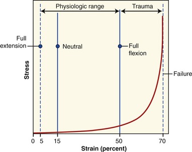
In the cervical region the supraspinous ligaments are very well developed and extend cranially as the ligamentum nuchae. This tough membrane consists of a bilaminar strip of fibroelastic tissue that attaches between the cervical spinous processes and external occipital protuberance.188 Passive tension in a stretched ligamentum nuchae adds a small but useful means of support for the head and neck.53 The ligamentum nuchae also provides a midline attachment for muscles, such as the trapezius and splenius capitis and cervicis. A prominent ligamentum nuchae accounts for some of the difficulty often encountered in palpating the spinous process in the mid to upper cervical region (Figure 9-13).
The intertransverse ligaments are poorly defined, thin or membranous structures that extend between adjacent transverse processes.188 These tissues become taut in contralateral lateral flexion and, to a lesser degree, forward flexion.
The anterior longitudinal ligament is a long, strong, straplike structure attaching to the basilar part of the occipital bone and the entire length of the anterior surfaces of all vertebral bodies, including the sacrum. The deeper fibers blend with and reinforce the anterior sides of the intervertebral discs.188 The anterior longitudinal ligament becomes taut in extension and slack in flexion.85 In the cervical and lumbar regions, tension in the anterior longitudinal ligament helps limit the degree of natural lordosis. This ligament is narrow at its cranial end but widens as it courses caudally.
The posterior longitudinal ligament is a continuous band of connective tissue that attaches the entire length of the posterior surfaces of the vertebral bodies, between the axis (C2) and the sacrum. The posterior longitudinal ligament is located within the vertebral canal, immediately anterior to the spinal cord (see Figure 9-11, A). (It is important to note that the posterior and anterior longitudinal ligaments are named according to their relationship to the vertebral body, not the spinal cord.) Throughout its length, the deeper fibers of the posterior longitudinal ligament blend with and reinforce the posterior side of the intervertebral discs.188 Cranially, the posterior longitudinal ligament is a broad structure, narrowing as it descends toward the lumbar region. The slender lumbar portion limits its ability to restrain a posterior bulging (or herniated) disc. As with most ligaments of the vertebral column, the posterior longitudinal ligament becomes increasingly taut with flexion.85
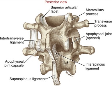
Capsular ligaments of the apophyseal joints consist mostly of collagen fibers that attach along the rim of the facet surfaces (see Figure 9-11, A). As will be described in an upcoming section on arthrology, apophyseal joints help interconnect and stabilize the intervertebral junctions. Equally important is their unique role in guiding the specific direction of intervertebral movement. Sensory mechanoreceptors embedded within the capsule likely provide muscles information to assist with this guidance.36 The apophyseal joint capsules are reinforced by adjacent muscles (multifidus) and ligamenta flava, most notably in the lumbar region.188
The capsular ligaments of the apophyseal joints are strong, capable of supporting up to 1000 N (225 lb) of tension before failure.48 The capsular ligaments are relatively loose (lax) in the neutral position but become increasingly taut as the joint approaches the extremes of all its movements. Passive tension is greatest in motions that create the largest translation or separation between joint surfaces. These kinematics are highly specific to the particular region of the vertebral column and will be revisited in subsequent sections of this chapter.
In closing, with the possible exception of the capsular ligaments of the apophyseal joints, knowledge of a ligament’s location relative to the axis of rotation within a given intervertebral junction provides major insight into its primary functions. As will be further described in an upcoming section, the axis of rotation for intervertebral movement is near or through the region of the vertebral body. When sagittal plane movement is considered, for example, any ligament located posterior to the vertebral body is stretched during flexion. Conversely, any ligament located anterior to the vertebral body is stretched during extension. As noted by reviewing Figure 9-11, A, all ligaments except the anterior longitudinal ligament would become taut in flexion.
Regional Osteologic Features of the Vertebral Column
The adage that “function follows structure” is very applicable to the study of the vertebral column. Although all vertebrae have a common morphologic theme, each also has a specific shape that reflects its unique function. The following section, along with Table 9-4, highlights specific osteologic features of each region of the vertebral column.
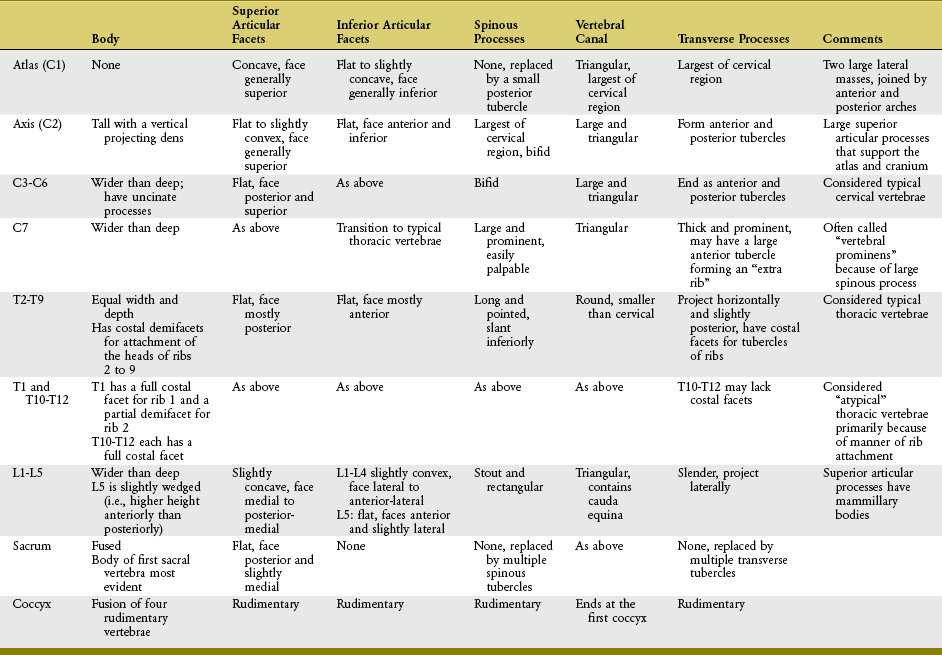
CERVICAL REGION
The cervical vertebrae are the smallest and most mobile of all movable vertebrae. The high degree of mobility is essential to the large range of motion required by the head. Perhaps the most unique anatomic feature of the cervical vertebrae is the presence of transverse foramina located within the transverse processes (Figure 9-14). The important vertebral artery ascends through this foramen, coursing toward the foramen magnum to transport blood to the brain and spinal cord. In the neck, the vertebral artery is located immediately anterior to the exiting spinal nerve roots (see Figure 9-4).
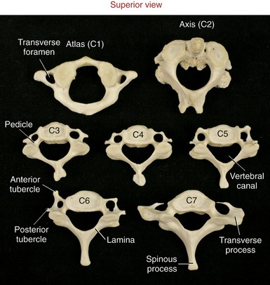
FIGURE 9-14. A superior view of seven cervical vertebrae.
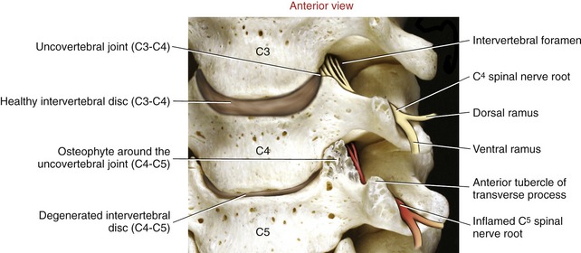
Typical Cervical Vertebrae (C3 to C6): C3 to C6 have small rectangular bodies made of a relatively dense and strong cortical shell.199 The bodies are wider from side to side than front to back (Figures 9-14 and 9-15). The superior and inferior surfaces of the bodies are not as flat as those of most other vertebrae but are curved or notched. The superior surfaces are concave side to side, with raised lateral hooks called uncinate processes (uncus means “hook”). The inferior surfaces, in contrast, are concave anterior-posterior, with elongated anterior and posterior margins. When articulated, small, synovial-lined uncovertebral joints form between the uncinate process and adjacent part of the superior vertebra between C3 and C7. Uncovertebral joints are often called the “joints of Luschka,” named after the person who first described them.84 The exact function of uncovertebral joints is unclear, although they likely facilitate the kinematics of cervical motion. Clinically these joints become important when osteophytes form around their margins, often reducing the size of the adjacent intervertebral foramen. If large, these osteophytes may impinge on and irritate exiting cervical spinal nerve roots, thereby causing neurologic symptoms.
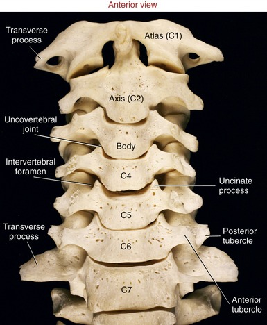
FIGURE 9-15. An anterior view of the cervical vertebral column.
SPECIAL FOCUS 9-1  Cervical Osteophytes Causing Neurologic Symptoms in the Upper Extremity: One Possible Consequence of a Degenerated Intervertebral Disc
Fully hydrated and normal intervertebral discs naturally act as “spacers” between individual vertebrae. One benefit of this function is to partially unload the nearby uncovertebral joints. Lacking substantial articular cartilage, the relatively small uncovertebral joints are not designed to support large forces. Figure 9-16 illustrates how a healthy, full disc located between C3 and C4 creates a small protective gap between the adjacent C3-C4 uncovertebral joint. Figure 9-16 also shows how a degenerated and thinned disc between C4 and C5 increases the compression force at the C4-C5 uncovertebral joint. Over time, the increased compression can stimulate growth of an osteophyte (“bone spur”). The osteophyte is shown compressing elements of the C5 spinal nerve root, which may, over time, lead to neurologic symptoms, including radiating (radicular) pain, muscle weakness, or altered sensations throughout the nerve’s peripheral distribution, typically down the lateral aspect of the arm. In an indirect way, healthy intervertebral discs protect not only the surrounding bone, but also the nerve roots.
The pedicles of C3 to C6 are short and curved posterior-lateral (see Figure 9-14). Very thin laminae extend posterior-medially from each pedicle (Figure 9-17). The triangular vertebral canal is large in the cervical region in order to accommodate the thickening of the spinal cord associated with the formation of the cervical plexus and brachial plexus.
Within the C3 to C6 region, consecutive superior and inferior articular processes form a continuous articular “pillar,” interrupted by apophyseal joints (Figure 9-18). The articular facets within each apophyseal joint are smooth and flat, with joint surfaces oriented midway between the frontal and horizontal planes. The superior articular facets face posterior and superior, whereas the inferior articular facets face anterior and inferior.
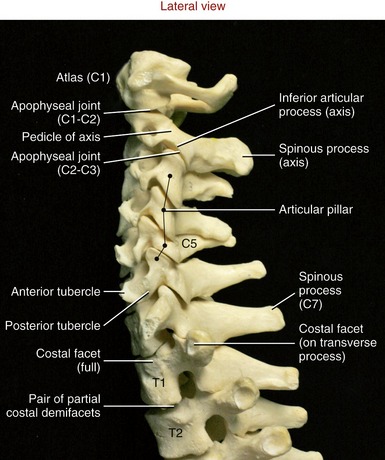
FIGURE 9-18. A lateral view of the cervical vertebral column.
The spinous processes of C3 to C6 are short, with some processes being bifid (i.e., double) (see Figure 9-14, C3). The transverse processes are short lateral extensions that terminate as variably shaped anterior and posterior tubercles. The tubercles are unique to the cervical region, serving as attachments for muscles, such as the anterior scalene, levator scapulae, and splenius cervicis.
Atypical Cervical Vertebrae (C1, C2, and C7):
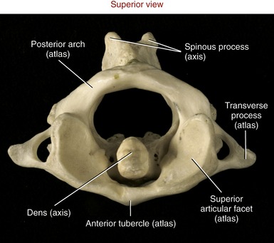
Atlas (C1): As indicated by the name, the primary function of the atlas is to support the head. Possessing no body, pedicle, lamina, or spinous process, the atlas is essentially two large lateral masses joined by anterior and posterior arches (Figure 9-19, A). The short anterior arch has an anterior tubercle for attachment of the anterior longitudinal ligament. The much larger posterior arch forms nearly half the circumference of the entire atlantal ring. A small posterior tubercle marks the midline of the posterior arch. The lateral masses support the prominent superior articular processes, which in turn support the cranium.
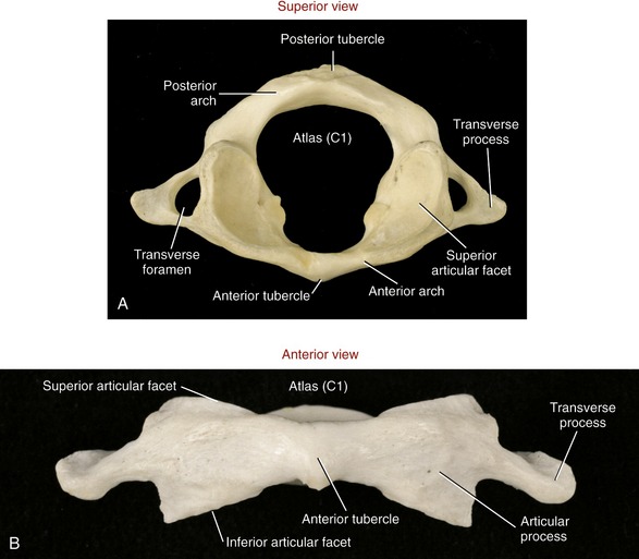
FIGURE 9-19. The atlas. A, Superior view. B, Anterior view.
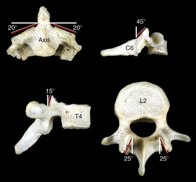
The large and concave superior articular facets of the atlas generally face cranially, in a position to accept the large, convex occipital condyles. The inferior articular facets are generally flat to slightly concave. These facet surfaces generally face inferiorly, with their lateral edges sloped downward, approximately 20 degrees from the horizontal plane (see Figure 9-19, B). The atlas has large, palpable transverse processes, usually the most prominent of the cervical vertebrae. These transverse processes serve as attachment points for several small but important muscles that control fine movements of the cranium.
Axis (C2): The axis has a large, tall body that serves as a base for the upwardly projecting dens (odontoid process) (Figure 9-20). Part of the elongated body is formed from remnants of the body of the atlas and the intervening disc. The dens provides a rigid vertical axis of rotation for the atlas and head (Figure 9-21). Projecting laterally from the body is a pair of superior articular processes (see Figure 9-20, A). These large processes have slightly convex superior articular facets that are oriented about 20 degrees from the horizontal plane, matching the slope of the inferior articular facets of the atlas. Projecting from the prominent superior articular processes of the axis are a pair of stout pedicles and a pair of very short transverse processes (see Figure 9-20, B). A pair of inferior articular processes projects inferiorly from the pedicles, with inferior articular facets facing anteriorly and inferiorly (see Figure 9-18). The spinous process of the axis is bifid and very broad. The palpable spinous process serves as an attachment for many muscles, such as the semispinalis cervicis.
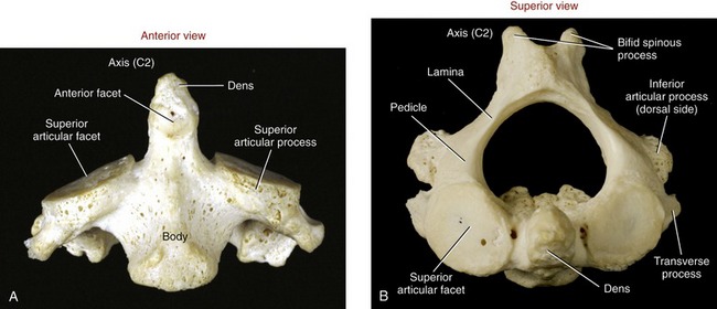
FIGURE 9-20. The axis. A, Anterior view. B, Superior view.
“Vertebra Prominens” (C7): C7 is the largest of all cervical vertebrae, having many characteristics of thoracic vertebrae. C7 can have large transverse processes, as illustrated in Figure 9-15. A hypertrophic anterior tubercle on the transverse process may sprout an extra cervical rib, which may impinge on the brachial plexus. This vertebra also has a large spinous process, characteristic of other thoracic vertebrae (see Figure 9-18).
THORACIC REGION
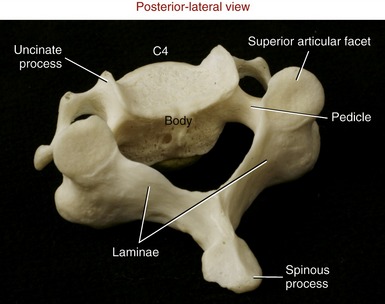
Typical Thoracic Vertebrae (T2 to T9): The second through the ninth thoracic vertebrae usually demonstrate similar features (see T6 and T7 in Figure 9-5). Pedicles are directed posteriorly from the body, making the vertebral canal narrower than in the cervical region. The large transverse processes project posterior-laterally, each containing a costal facet that articulates with the tubercle of the corresponding rib (costotransverse joint). Short, thick laminae form a broad base for the downward-slanting spinous processes.
The superior and inferior articular facets in the thoracic region are oriented vertically with a slight forward pitch (Figure 9-22). The superior articular facets face generally posterior; the inferior articular facets face generally anterior. Once articulated, the superior and inferior facets form apophyseal joints, which are aligned relatively close to the frontal plane.
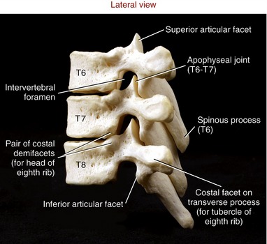
Each of the heads of ribs 2 through 9 typically articulates with a pair of costal demifacets that span one thoracic intervertebral junction (see pair of costal demifacets for the eighth rib in Figure 9-22). As described earlier, these articulations are called costocorporeal joints. A thoracic (intercostal) spinal nerve exits through a corresponding thoracic intervertebral foramen, located just anterior to the apophyseal joints.
Atypical Thoracic Vertebrae (T1 and T10 to T12): The first and usually last three thoracic vertebrae are considered atypical mainly because of the particular manner of rib attachment. T1 has a full costal facet superiorly that accepts the entire head of the first rib, and a demifacet inferiorly that accepts part of the head of the second rib (see Figure 9-18). The spinous process of T1 is especially elongated and often as prominent as the spinous process of C7. Although variable, the bodies of T10 through T12 may have a single, full costal facet for articulation with the heads of the tenth, eleventh, and twelfth ribs, respectively. T10 to T12 usually lack costotransverse joints.
LUMBAR REGION
Lumbar vertebrae have massive wide bodies, suitable for supporting the entire superimposed weight of the head, trunk, and arms (Figure 9-23). The total mass of the five lumbar vertebrae is approximately twice that of all seven cervical vertebrae.
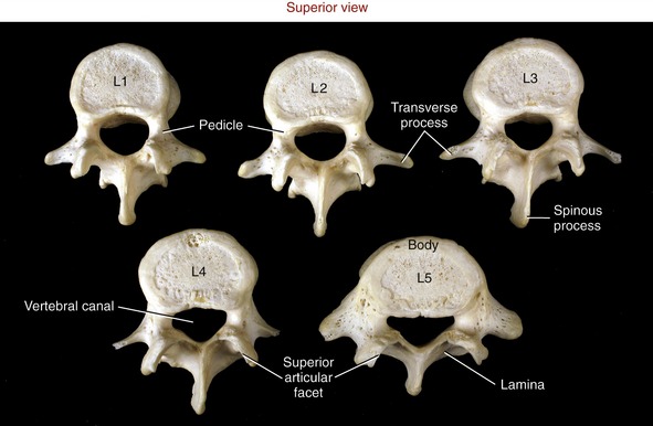
FIGURE 9-23. A superior view of the five lumbar vertebrae.
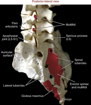
For the most part, the lumbar vertebrae possess similar characteristics. Laminae and pedicles are short and thick, forming the posterior and lateral walls of the nearly triangular vertebral canal. Transverse processes project almost laterally; those associated with L1 to L4 are thin and tapered; however, the transverse processes of L5 are short, thick, and strong. Spinous processes are broad and rectangular, projecting horizontally from the junction of each lamina (Figure 9-24). This shape is strikingly different from the pointed, sloped spinous processes of the thoracic region. Short mammillary processes project from the posterior surfaces of each superior articular process. These structures serve as attachment sites for the multifidi muscles.
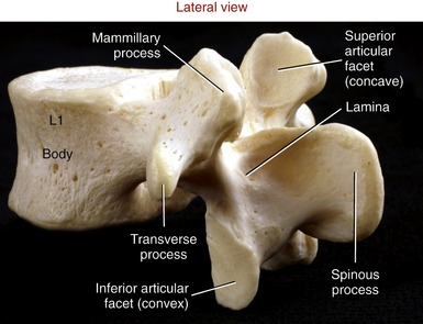
The articular facets of the lumbar vertebrae are oriented nearly vertically. The superior articular facets are moderately concave, facing medial to posterior-medial. As depicted in Figure 9-23, the superior facet surfaces in the upper lumbar region tend to be oriented closest with the sagittal plane, and the superior facet surfaces in the mid-to-lower lumbar region are oriented approximately midway between the sagittal and frontal planes. The inferior articular facets are reciprocally matched to the shape and orientation of the superior articular facets. In general, the inferior articular facets are slightly convex, facing generally lateral to anterior-lateral (see Figure 9-24).
SPECIAL FOCUS 9-2  Developmental Anomalies of the Lumbar Apophyseal Joints
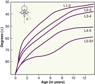
At birth the articular surfaces of the apophyseal joints within the lumbar spine are oriented very close to the frontal plane, similar to most thoracic apophyseal joints. Between birth and about 11 or 12 years of age, however, the orientation within all but the lower lumbar apophyseal joints gradually transforms to their final adult position biased slightly closer to the sagittal plane (Figure 9-25).23,167 The slow structural transformation is governed by different rates of ossification within the articular processes. Bogduk describes the possibility that this transformation may be influenced by the developing upright posture of the child and the demands placed on certain muscles, such as the lumbar multifidi.23 Although the apophyseal joints continue to grow throughout adolescence, their spatial orientation is essentially established before the teenage years.
Natural variations in the development of the lumbar apophyseal joints in childhood can create structural variations that persist into adulthood. Although variations can be extreme, most are relatively minor, such as a slight bilateral asymmetry between the right and left articular surfaces of the joints. (An example of this asymmetry is evident by comparing the superior articular facets of the lumbar vertebrae illustrated in Figure 9-23.) Slight bilateral asymmetries exist in about 20% to 30% of all adult lumbar vertebrae, although they are likely inconsequential.23 In more extreme cases, however, the bilateral asymmetry could create uneven stress and instability throughout the intervertebral junctions.47 Although evidence is mixed, the increased stress could potentially predispose a person to premature degeneration in the apophyseal joints or intervertebral discs.63
SACRUM
The sacrum is a triangular bone with its base facing superiorly and apex inferiorly (Figure 9-26). An important function of the sacrum is to transmit the weight of the vertebral column to the pelvis. In childhood, each of five separate sacral vertebrae is joined by a cartilaginous membrane. By adulthood, however, the sacrum has fused into a single bone, which still retains some anatomic features of generic vertebrae.
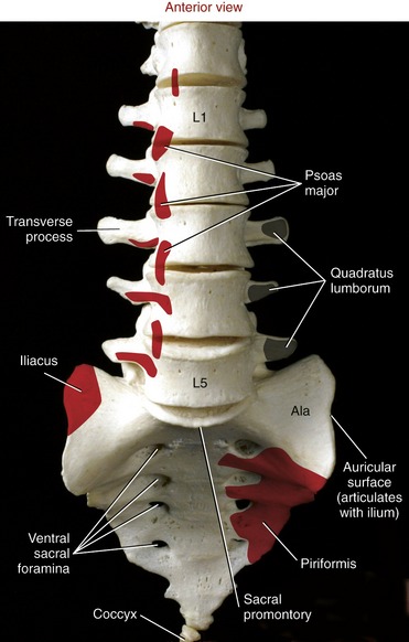
The anterior (pelvic) surface of the sacrum is smooth and concave, forming part of the posterior wall of the pelvic cavity (see Figure 9-26). Four paired ventral (pelvic) sacral foramina transmit the ventral rami of spinal nerve roots that form much of the sacral plexus. The dorsal surface of the sacrum is convex and rough due to the attachments of muscle and ligaments (Figure 9-27). Several spinal and lateral tubercles mark the remnants of fused spinous and transverse processes, respectively. Four paired dorsal sacral foramina transmit the dorsal rami of sacral spinal nerve roots.
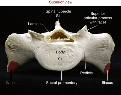
The superior surface of the sacrum shows a clear representation of the body of the first sacral vertebra (Figure 9-28). The sharp anterior edge of the body of S1 is called the sacral promontory. The triangular sacral canal houses and protects the cauda equina. Pedicles are very thick, extending laterally as the ala (lateral wings) of the sacrum. Stout superior articular processes have superior articular facets that face generally posterior-medially. These facets articulate with the inferior facets of L5 to form L5-S1 apophyseal joints (see Figure 9-27). The large auricular surface articulates with the ilium, forming the sacroiliac joint. The sacrum narrows caudally to form its apex, a point of articulation with the coccyx.
COCCYX
The coccyx is a small triangular bone consisting of four fused vertebrae (see Figure 9-27). The base of the coccyx joins the apex of the sacrum at the sacrococcygeal joint. The joint has a fibrocartilaginous disc and is held together by several small ligaments. The sacrococcygeal joint usually fuses late in life. In youths, small intercoccygeal joints persist; however, these typically are fused in adults.188
SPECIAL FOCUS 9-3  Cauda Equina
At birth the spinal cord and vertebral column are nearly the same length. Thereafter, however, the vertebral column grows at a slightly faster rate than the spinal cord. As a consequence, in the adult the caudal end of the spinal cord terminates generally adjacent to the L1 vertebra. The lumbosacral spinal nerve roots therefore must travel a great distance caudally before reaching their corresponding intervertebral foramina (see Figure III-1 in Appendix III, Part A). As a group, the elongated nerves resemble a horse’s tail, hence the term cauda equina.
ARTHROLOGY
Typical Intervertebral Junction
The typical intervertebral junction has three functional components: (1) the transverse and spinous processes, (2) the apophyseal joints, and (3) an interbody joint (Figure 9-29). The spinous and transverse processes provide mechanical outriggers, or levers, that increase the mechanical leverage of muscles and ligaments. Apophyseal joints are primarily responsible for guiding intervertebral motion, much as railroad tracks guide the direction of a train. As will be emphasized, the geometry, height, and spatial orientation of the articular facets within the apophyseal joints greatly influence the prevailing direction of intervertebral motion.
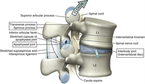
Interbody joints connect an intervertebral disc with a pair of vertebral bodies. The primary function of these joints is to absorb and distribute loads across the vertebral column. Normally, at least in the lumbar region, the interbody joint accepts the overwhelming majority of weight that is borne through the intervertebral junction. As indicated in Figure 9-29, flexion of the spine shifts an even greater proportion of the superimposed body weight forward to the interbody joint. In addition, the interbody joints provide the greatest source of adhesion between vertebrae,85 serve as the approximate axes of rotation, and function as deformable intervertebral spacers. As spacers, the intervertebral discs constitute about 25% of the total height of the vertebral column. The functional importance of the space created by a healthy intervertebral disc cannot be overstated. The greater the relative intervertebral space, the greater the ability of one vertebral body to “rock” forward and backward on another, for example. Without any disc space, the nearly flat bone-on-bone interface between two consecutive bodies would block rotation in the sagittal and frontal planes—allowing only tipping or translation. Finally, the space created by the intervertebral discs provides adequate passage for the exiting spinal nerve roots.
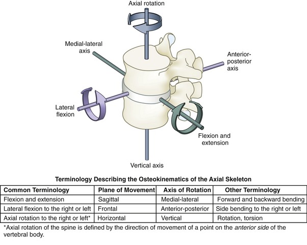
TERMINOLOGY DESCRIBING MOVEMENT
With few important exceptions, movement within any given intervertebral junction is relatively small. When added across the entire vertebral column, however, these small movements can yield considerable angular rotation. The osteokinematics across the entire axial skeleton (which includes the vertebral column and cranium) are described as rotations within the three cardinal planes. Each plane, or degree of freedom, is associated with one axis of rotation, directed approximately through the body of the interbody joint (Figure 9-30).174 By convention, movement throughout the vertebral column, including the head on the cervical spine, is described in a cranial-to-caudal fashion, with the direction of movement referenced by a point on the anterior side of the more cranial (superior) vertebral segment. During C4-C5 axial rotation to the left, for example, a point on the anterior body of C4 rotates to the left, although the spinous process rotates to the right.
Arthrokinematics of intervertebral motion describe the relative movement between articular facet surfaces within the apophyseal joints. Most facet surfaces are flat or nearly flat, and terms such as approximation, separation (or gapping), and sliding adequately describe the arthrokinematics (Table 9-5).
TABLE 9-5.
Terminology Describing the Arthrokinematics at the Apophyseal Joints
| Terminology | Definition | Functional Example |
| Approximation of joint surfaces | An articular facet surface tends to move closer to its partner facet. Joint approximation is usually caused by a compression force. | Axial rotation between L1 and L2 typically causes an approximation (compression) of the contralateral apophyseal joint |
| Separation (gapping) between joint surfaces | An articular facet surface tends to move away from its partner facet. Joint separation is usually caused by a distraction force. | Therapeutic traction as a way to decompress or separate the apophyseal joints |
| Sliding (gliding) between joint surfaces | An articular facet translates in a linear or curvilinear direction relative to another articular facet. Sliding between joint surfaces is caused by a force directed tangential to the joint surfaces. | Flexion-extension of the mid to lower cervical spine |
STRUCTURE AND FUNCTION OF THE APOPHYSEAL JOINTS
The vertebral column contains 24 pairs of apophyseal joints. Each apophyseal joint is formed between opposing articular facet surfaces (Figure 9-31). Mechanically classified as plane joints, apophyseal joints are lined with articular cartilage and enclosed by a synovial-lined, well innervated capsule. Although exceptions and natural variations are common, the articular surfaces of most apophyseal joints are essentially flat. Slightly curved joint surfaces are present primarily in the upper cervical and throughout the lumbar regions.
The orientation of the plane of the facet surfaces within each joint strongly influences the kinematics at different regions across the vertebral column. As a general rule, horizontal facet surfaces favor axial rotation, whereas vertical facet surfaces (in either sagittal or frontal planes) block axial rotation. Most apophyseal joint surfaces, however, are oriented somewhere between the horizontal and vertical. Figure 9-32 shows the typical joint orientation for superior articular facets in the cervical, thoracic, and lumbar regions. The plane of the facet surfaces explains, in part, why axial rotation is far greater in the cervical region than in the lumbar region. Additional factors that influence the predominant motion at each spinal region include the sizes of the intervertebral discs (relative to the associated vertebral bodies), the overall shape of the vertebrae, local muscle actions, and attachments made by ribs or ligaments.
SPECIAL FOCUS 9-4  Intra-articular Structures Located within Apophyseal Joints
Small and inconsistently formed accessory structures (inclusions) are typically found around the margins of apophyseal joints, most frequently described in the upper cervical and the lumbar regions.23,129 In the lumbar spine, Bogduk describes two primary types of accessory structures: subcapsular fat pads and fibro-adipose meniscoids.23 Subcapsular fat pads fill small crevices formed between the capsule and the underlying synovial membrane, typically at the superior and inferior margins of the joint. The subcapsular fat pads may extend outside the joint through very small crevices in the capsule. When fully formed, larger extracapsular fat pads within the lumbar region fill part of the space between the lamina and the overlying multifidi muscles.
Fibro-adipose meniscoids are another set of connective tissue found at the periphery of apophyseal joints. These structures range from thickenings or “pleats” of connective tissue variously placed along the internal surface of the joint capsule, to folds of synovium that encapsulate small fat pads, collagen fibers, and blood vessels. The larger fibro-adipose meniscoids can extend several millimeters into the apophyseal joint.23
The function of intra-articular inclusions within apophyseal joints is controversial. Some authors have described them as deformable spacers that help dissipate compression forces within the joint.73,129 Others have speculated that the structures are designed to partially cover the articular cartilage that becomes exposed at the extremes of motion.23 This transient coverage may protect and lubricate the exposed surfaces until the joint is returned to its neutral position. Although opinions vary, the intra-articular inclusions may have important clinical relevance. The larger fibro-adipose meniscoids in cervical regions may become impinged as the apophyseal joints forcefully hyperextend, such as during a cervical whiplash injury.99 Meniscoids may proliferate after long-term immobilization and restrict spinal movement. Because these tissues are innervated, they may be a source of pain.74
STRUCTURE AND FUNCTION OF THE INTERBODY JOINTS
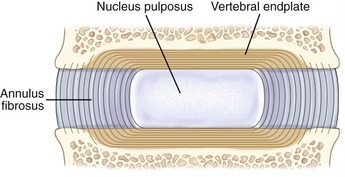
From C2-C3 and L5-S1, 23 interbody joints can be found in the spinal column. Each interbody joint contains an intervertebral disc, vertebral endplates, and adjacent vertebral bodies. Anatomically, this joint is classified as a cartilaginous synarthrosis (see Chapter 2).
Structural Considerations of the Lumbar Intervertebral Discs: Most of what is known about the structure and function of intervertebral discs is based on research performed in the lumbar region.23 The research focus reflects the region’s disproportionately high frequency of disc degeneration, especially in the lower vertebral segments.
A lumbar intervertebral disc consists of a central nucleus pulposus surrounded by an annulus fibrosus (Figure 9-33). The nucleus pulposus is a pulplike gel located in the mid-to-posterior part of the disc. In youth the nucleus pulposus within the lumbar discs consists of 70% to 90% water.188 The hydrated nucleus allows the disc to function as a modified hydraulic shock absorption system, capable of continuously dissipating and transferring loads across consecutive vertebrae. The nucleus pulposus is thickened into a gel-like consistency by relatively large branching proteoglycans. Each proteoglycan is an aggregate of many water-binding glycosaminoglycans linked to core proteins (see Chapter 2).6,66 Dispersed throughout the hydrated proteoglycan mixture are thin type II collagen fibers, elastin fibers, and other proteins. The collagen forms an infrastructure that helps support the proteoglycan network. Very small numbers of chondrocytes and fibrocytes are interspersed throughout the nucleus, ultimately responsible for the synthesis and regulation of the proteins and proteoglycans. In the very young, the nucleus pulposus contains a few chondrocytes that are remnants of the primitive notochord.169,188
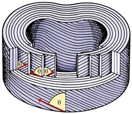
The annulus fibrosus in the lumbar discs consists primarily of 15 to 25 concentric layers, or rings, of collagen fibers.23 Like dough surrounding jelly in a doughnut, the collagen rings encase and physically entrap the liquid-based central nucleus. The annulus fibrosus contains material and cells similar to what is found in the nucleus pulposus, differing mainly in proportion. In the annulus, collagen makes up about 50% to 60% of the dry weight, as compared with only 15% to 20% in the nucleus pulposus.23 Abundant elastin protein is interspersed in parallel to the rings of collagen, bestowing an element of circumferential elasticity to the annulus fibrosus.225
The outermost or peripheral layers of the annulus fibrosus consist primarily of type I and type II collagen.35 This arrangement provides circumferential strength and flexibility to the disc, as well as a means to bond the annulus to the anterior and posterior longitudinal ligaments and to the adjacent rim of the vertebral bodies and endplates. (The outer layers of the annulus fibrosus contain the disc’s only sensory nerves; see innervation of the disc, Chapter 10). The deeper, internal layers of the annulus contain less type I collagen and more water—gradually transforming into tissue with characteristics similar to those of the centrally located nucleus pulposus.228
Normally, compression forces acting on the disc increase the hydrostatic pressure within the water-logged nucleus pulposus. This rise in and containment of hydrostatic pressure ultimately absorb and evenly distribute loads across the entire intervertebral junction. Fully hydrated and pressurized discs protect not only the interbody joints, but also, indirectly, the apophyseal joints. A dehydrated and thinned disc places disproportionately greater compressive loads on the apophyseal joints. For this reason, some authorities claim that a degenerated disc leads to subsequent arthritis (or arthrosis) of the apophyseal joints.97 Some authors, however, argue the opposite cause-and-effect relationship—that the loss of joint space within a degenerated apophyseal joints favors disc degeneration.61 Both arguments are indeed valid.
The intervertebral discs are very important stabilizers of the spine. This stabilizing function is primarily a result of the structural configuration of the collagen fibers within the annulus fibrosus. As shown in Figure 9-34, most fibers are oriented in a rather precise geometric pattern. In the lumbar region, collagen rings are oriented, on average, about 65 degrees from the vertical, with fibers of adjacent layers traveling in opposite directions.23,122 This structural arrangement offers significant resistance against intervertebral distraction (vertical separation), shear (sliding), and torsion (twisting).85 If the embedded collagen fibers ran nearly vertically, the disc would most effectively resist distraction forces, but not sliding or torsion. In contrast, if all fibers ran nearly parallel to the top of the vertebral body, the disc would most effectively resist shear and torsion, but not distraction. The 65-degree angle likely represents a geometric compromise that permits tensile forces to be applied primarily against the most natural movements of the lumbar spine. Distraction forces are an inherent component of flexion, extension, and lateral flexion, occurring as one vertebral body tips slightly and thus separates from its neighbor. Shear and torsion forces are produced during virtually all movements of the vertebral column. Because of the alternating layering of the annulus, only collagen fibers oriented in the direction of the slide or twist become taut; fibers in every other layer slacken.
In contrast to the lumbar region, the annulus fibrosus in the cervical region does not have complete concentric rings that surround the nucleus.130 When a cervical disc is viewed from above, the annulus has a near-crescent shape, thick along the anterior rim and progressively tapering to a very thin layer at the disc’s lateral margins. Little or no annular fibers exist at the region of the uncovertebral joints. A small fissure (or cleft) typically extends horizontally inward from each uncovertebral joint, coursing to the deeper regions of the disc.130 Although the function of the fissures is uncertain, they likely increase the freedom of movement within the cervical region. The posterior annulus is separate from the anterior and lateral regions; it is thin and oriented vertically, parallel with the adjacent posterior longitudinal ligament.130
Vertebral Endplates: The vertebral endplates in the adult are relatively thin cartilaginous caps of connective tissue that cover most of the superior and inferior surfaces of the vertebral bodies (see Figure 9-33). At birth the endplates are very thick, accounting for about 50% of the height of each intervertebral space. During childhood the endplates function as growth plates for the vertebrae; in the adult the endplates recede and occupy only about 5% of the height of each intervertebral space.169
The surface of the vertebral endplate that faces the disc is composed primarily of fibrocartilage, which binds directly and strongly to the collagen within the annulus fibrosus (Figure 9-35). This fibrocartilaginous bond forms the primary adhesion between consecutive vertebrae. In contrast, the surface of the endplate that faces the vertebral body is composed primarily of calcified cartilage that is weakly affixed to the bone. This endplate-bone interface is often described as the “weak link” within the interbody joint, often the first component of the interbody joint to fracture under high or repetitive compressive loading.136 A perforated or fractured endplate can allow the proteoglycan gel to leak from the nucleus pulposus, causing structural disruption of the disc.77,162 Such disruption has been shown to cause spinal instability.227
Only the outer, more peripheral rings of the annulus fibrosus contain blood vessels. For this reason, most of the disc has an inherently limited healing capacity. Essential nutrients, such as glucose and oxygen, must diffuse a great distance to reach the deeper cells that sustain the disc’s low but essential metabolism. The source of these nutrients is in the blood vessels located in the more superficial annulus and, more substantially, blood stored in the adjacent vertebral bodies.77 Most of these nutrients must diffuse across the vertebral endplate and through the disc’s extracellular matrix, eventually reaching the cells residing deep in the disc.62,165 These cells must receive nourishment to manufacture extracellular proteoglycans of the essential quantity and quality. Aged discs, for example, typically show reduced permeability and increased calcification of the vertebral endplates, which, in turn, reduce the flow of nutrients and oxygen into the disc.25,169 This age-related process can inhibit cellular metabolism and synthesis of proteoglycans. Less proteoglycan content reduces the ability of the nucleus to attract and retain water, thereby limiting its ability to effectively absorb and transfer loads.91
Intervertebral Disc as a Hydrostatic Pressure Distributor: The vertebral column is the primary support structure for the trunk and upper body. While one stands upright for example, approximately 80% of the load supported by two adjoining lumbar vertebrae is carried through the interbody joint; the remaining 20% is carried by posterior elements, such as apophyseal joints and laminae.5
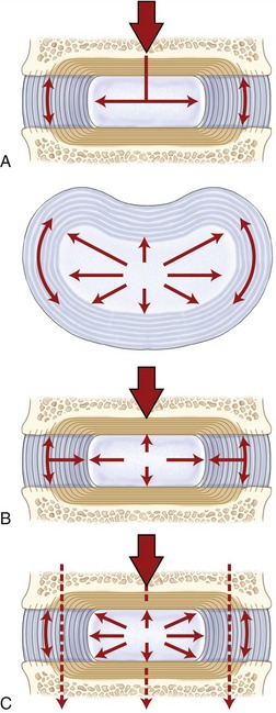
The intervertebral discs are uniquely designed as shock absorbers to protect the bone from excessive pressure that might result from body weight or strong muscle contraction. Compression forces push the endplates inward and toward the nucleus pulposus. Being filled mostly with water and therefore essentially incompressible, the young and healthy nucleus responds by deforming radially and outwardly against the annulus fibrosus (Figure 9-36, A). Radial deformation is resisted by the tension created within the stretched rings of collagen and elastin of the annulus fibrosus (see Figure 9-36, B). Pressure within the entire disc is thus uniformly elevated and transmitted evenly to the adjacent vertebra (see Figure 9-36, C). When the compressive force is removed from the endplates, the stretched elastin and collagen fibers return to their original preloaded length, ready for another compressive force. This mechanism allows compressive forces to be shared by multiple structures, thereby preventing a small spot of high pressure on any single tissue. Because it has viscoelastic properties, the intervertebral disc resists a fast or strongly applied compression more than a slow or light compression.101 The disc therefore can be flexible at low loads and relatively rigid at high loads.
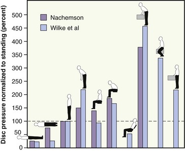
In Vivo Pressure Measurements from the Nucleus Pulposus: In vivo studies have confirmed that pressure within the nucleus pulposus in the lumbar region is relatively low at rest in the supine position.13,140,219 Much larger disc pressures occur from activities that combine forward bending and the need for vigorous trunk muscle contraction. Intradiscal pressures can rise to surprisingly high levels and can produce transient changes in the shape of even the healthy disc. Sustained flexion in the lumbar spine, for example, can reduce the height of the disc slightly as water is slowly forced outward. Sustained and full lumbar extension, in contrast, reduces the pressure in the disc; this allows water to be reabsorbed into the disc, thus reinflating it to its natural level.
In vivo data on pressure within the disc during movement and changes in posture have greatly increased the understanding of ways to reduce injury to the disc. Data produced by two separate studies are compared in Figure 9-37.138,219 Both studies reinforce three points: (1) disc pressures are large when one holds a load in front of the body, especially when bending forward; (2) lifting a load with knees flexed places less pressure on the lumbar disc than does lifting a load with the knees straight (the latter method typically generating more demands on the back muscles); and (3) sitting in a forward-slouched position produces greater disc pressure than sitting erect. These points serve as the theoretic basis for many educational programs designed for persons with disc degeneration, including disc herniation.
Diurnal Fluctuations in the Water Content within the Intervertebral Discs: When a healthy spine is unloaded, such as during bed rest, the pressure within the nucleus pulposus is relatively low.138 This relatively low pressure, combined with the hydrophilic nature of the nucleus pulposus, attracts water into the disc. As a result, the disc swells slightly when one is sleeping. When one is awake and upright, however, weight bearing produces compression forces across the vertebral endplates that push water out of the disc.94 The natural cycle of swelling and contraction of the disc produces on average a 1% diurnal variation in overall body height.201 The daily variation has a strong inverse relation to age. Karakida and colleagues used magnetic resonance imaging (MRI) to measure the variation in water content in the discs of a group of working persons between the ages of 23 and 56 years old, with no medical history of low-back pain.100 Remarkably, significant diurnal variation in water content was found only in the discs of persons younger than 35 years of age. These findings are consistent with the fact that the water-retaining capacity of intervertebral discs naturally declines with increasing age.6,14 The relative dehydration is caused by the parallel, age-related decline in the discs’ proteoglycan content.158,203
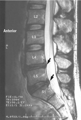
A relatively dehydrated nucleus pulposus exerts less hydrostatic pressure when compressed.23 Once relatively depressurized, the disc may bulge outward when compressed, similar to a “flat tire.” The older, degenerated intervertebral disc is subsequently less able to uniformly cushion the vertebral body and endplates against compressive loads.145 As a consequence, disc degeneration increases with age and affects most persons, to varying degrees, over 35 or 40 years of age.78,100,158,164,206 A diagnosis of disc degeneration is most effectively made using MRI, typically based on a diminished signal intensity of the T2-weighted image (indicative of reduced water content), loss of distinction between the border of the annulus fibrosus and the nucleus pulposus, nuclear bulging, and loss of disc space.78,100,157,164 The MRI scan in Figure 9-38 shows diminished signal intensity between L4-L5 and L5-S1 along with nuclear bulging. Furthermore, a degenerated disc may display circumferential, radial, and peripheral fissures (clefts) within the annulus.78 According to Adams, these fissures can often be observed even in young adolescent persons.6 Excessive degeneration may also be associated with complete depressurization of the nucleus in conjunction with delamination of the annular fibers and microfractures of the vertebral endplates.78 In some cases the internal disruption of the annular fibers may lead to a herniation (prolapse) of the nucleus pulposus (typically posteriorly toward or into the spinal canal). Remarkably, a significant percentage of persons with observable signs of disc degeneration on MRI remain asymptomatic, without experiencing continued mechanical deterioration or loss of function.95 The important topic of disc degeneration, including disc herniation, is described in more detail later in this chapter.
REGIONAL ANATOMY AND KINEMATICS ACROSS THE VERTEBRAL COLUMN
This section describes the anatomy and the kinematics throughout the various regions of the vertebral column. For each region, a maximum expected range of motion will be cited, assuming a starting, neutral position (Figure 9-39).82,106,121 The reported range of motion in the literature is highly variable, reflecting differences in research design and differences resulting from the gender, age, and activity level of the subjects.198 Data also vary for active and passive movements, means used to stabilize the subject, and the tools used to measure the motion. Methods typically include the use of goniometers (manual, electrical, or fiberoptic), flexible rulers, or inclinometers or more sophisticated tools that employ three-dimensional MRI, planar and biplanar radiography, videofluoroscopy, ultrasonography, and computerized analysis using electromechanical, potentiometric, optical, or electromagnetic tracking systems.*
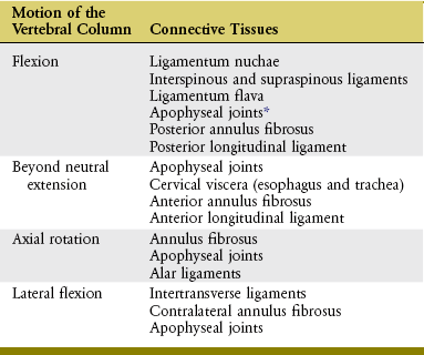
The connective tissues within the vertebral column play a major role in limiting and therefore defining the normal limits of motion across regions; selected examples are provided in Table 9-6. In cases of disease, trauma, or extended times of immobilization, these connective tissues may become abnormally stiff, thus interfering with normal kinematics. Understanding the structures’ normal function is a prerequisite for the design of treatments aimed to increase intervertebral mobility.85
TABLE 9-6.
Selected Examples of Connective Tissues That May Limit Motions of the Vertebral Column
*Depending on the movement, resistance generated by apophyseal joints may be caused by excessive approximation within the joint, increased tension within the capsule, or a combination of factors.
Introduction to Spinal Coupling
The mechanical explanations for the cause of most purported spinal coupling patterns are varied and typically unclear. Explanations may include muscle action, articular facet alignment within apophyseal joints, preexisting posture, attachment of ribs, stiffness of connective tissues, and geometry of the physiologic curve itself.42,58,111,135,182 The last explanation, rooted more in mechanics than biology, may be demonstrated by using a flexible rod as a model of the spine. Bend the rod about 30 to 40 degrees in one plane to mimic the natural lordosis or kyphosis of a particular region. While maintaining this curve, “laterally flex” the rod and note a slight automatic axial rotation. The biplanar bend placed on a flexible rod apparently creates unequal strains that are dissipated as torsion. This demonstration does not explain all coupling patterns observed clinically throughout the vertebral column, however.
Although some manual therapists incorporate spinal coupling into their assessment and treatment of spinal dysfunction, little consensus exists as to which coupling pattern is considered normal for a specific region.42,111,182 One important exception is the relatively consistent coupling pattern that is naturally expressed between lateral flexion and rotation in the craniocervical region.42,92 The specifics of this coupling pattern are described in detail in the section on kinematics of the craniocervical region.
Further study is needed to define a consistent spinal coupling pattern in the thoracic and lumbar regions. The motions of lateral flexion and axial rotation have indeed been shown to be coupled, although not consistently across multiple, controlled studies.111,182 The inconsistency may reflect the natural variability of the phenomenon in these regions, as well as inadequate or different testing methodologies or conditions, dissimilar subject populations, or, more likely, a combination of these factors. Using a specific coupling pattern in the mid-to-lower thoracic and lumbar regions to direct a patient’s evaluation and treatment should be done with caution and respect for its inconsistent and, at times, elusive nature.
Craniocervical Region
The terms “craniocervical region” and “neck” are used interchangeably. Both terms refer to the combined set of three articulations: atlanto-occipital joint, atlanto-axial joint complex, and intracervical apophyseal joints (C2 to C7). The overall organization used to present the regional anatomy and kinematics of the craniocervical region is outlined in Box 9-1. The upcoming section begins with an overview of the anatomy followed by a discussion of the kinematics, organized by plane of movement.
ANATOMY OF JOINTS
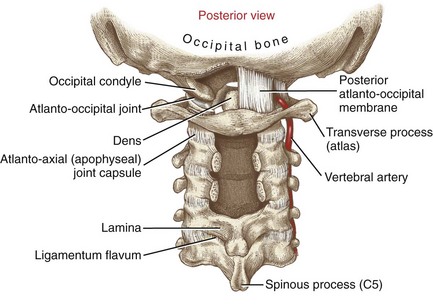
Atlanto-occipital Joint: The atlanto-occipital joints provide independent movement of the cranium relative to the atlas. The joints are formed by the protruding convex condyles of the occipital bone fitting into the reciprocally concave superior articular facets of the atlas (Figure 9-40). The congruent convex-concave relationship provides inherent structural stability to the articulation.
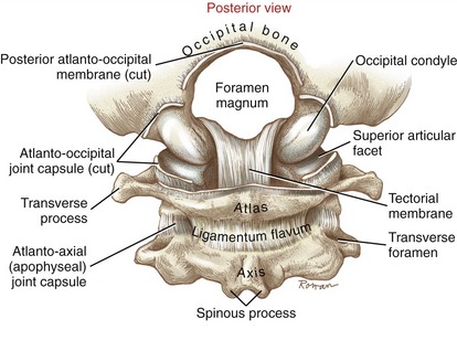
Anteriorly, the capsule of each atlanto-occipital joint blends with the anterior atlanto-occipital membrane (Figure 9-41). Posteriorly, the capsule is covered by a thin, broad posterior atlanto-occipital membrane (Figure 9-42). As depicted on the right side of Figure 9-42, the vertebral artery pierces the posterior atlanto-occipital membrane to enter the foramen magnum. This crucial artery supplies blood to the brain.
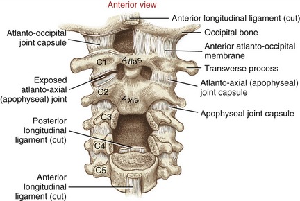
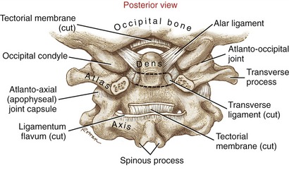
Atlanto-axial Joint Complex: The atlanto-axial joint complex has two articular components: a median joint and a pair of laterally positioned apophyseal joints. The median joint is formed by the dens of the axis (C2) projecting through an osseous-ligamentous ring created by the anterior arch of the atlas and the transverse ligament (Figure 9-43). Because the dens serves as a vertical axis for horizontal plane rotation of the atlas, the atlanto-axial joint is often described as a pivot joint.
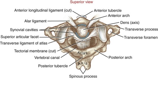
The median joint within the atlanto-axial joint complex has two synovial cavities. The smaller, anterior cavity is formed between the anterior side of the dens and the posterior border of the anterior arch of the atlas (see Figure 9-43). A small anterior facet on the anterior side of the dens marks this articulation (see Figure 9-20, A). The much larger posterior cavity separates the posterior side of the dens and a cartilage-lined section of the transverse ligament of the atlas. This strong, 2-cm long ligament is essential to the horizontal plane stability of the atlanto-axial articulation.33 Without its restraint, the atlas (and articulated cranium) can slip anteriorly relative to the axis, possibly damaging the spinal cord.68,172
The two apophyseal joints of the atlanto-axial joint are formed by the articulation of the inferior articular facets of the atlas with the superior facets of the axis (see exposed right joint in Figure 9-41). The surfaces of these apophyseal joints are generally flat and oriented close to the horizontal plane, a design that maximizes the freedom of axial rotation.
Tectorial Membrane and the Alar Ligaments: A review of the anatomy of the atlanto-axial joint complex must include a brief description of the tectorial membrane and the alar ligaments, connective tissues that help connect the cranium to the upper cervical spine. As discussed, the transverse ligament of the atlas makes firm contact with the posterior side of the dens (see Figure 9-43). Just posterior to the transverse ligament is a broad, firm sheet of connective tissue called the tectorial membrane (see Figure 9-40 and Figure 9-43). As a continuation of the posterior longitudinal ligament, the tectorial membrane attaches to the basilar part of the occipital bone, just anterior to the rim of the foramen magnum.188 There is limited published information on the function of the tectorial membrane. Based on attachments, however, the ligament likely provides generalized multidirectional stability to the craniocervical junction.
The alar ligaments are tough fibrous cords each about 1 cm in length with a thickness of a common pencil.33,57 As shown in Figure 9-44, each ligament passes laterally and slightly upward from the apex of the dens to the medial sides of the occipital condyles. Clinically referred to as “check ligaments,” the alar ligaments are respected for their ability to resist, or check, axial rotation of the head-and-atlas relative to the dens.149 The pair of ligaments is loose in the neutral position but becomes increasingly taut during axial rotation; the ligament located contralateral to the side of the rotation exhibits slightly greater resistance to the movement.45,57,172 In addition to limiting axial rotation, the alar ligaments also restrict the extremes of all other potential motions at the atlanto-occipital joint.
Intracervical Apophyseal Joints (C2 to C7): The facet surfaces within apophyseal joints of C2 to C7 are orientated like shingles on a 45-degree sloped roof, approximately halfway between the frontal and horizontal planes (see Figure 9-18, C2-C3 articulation). This orientation enhances the freedom of movement in all three planes, a hallmark of cervical arthrology.
SAGITTAL PLANE KINEMATICS
The craniocervical region is the most mobile region within the entire vertebral column. Highly specialized joints facilitate precise positioning of the head, involving vision, hearing, smell, and equilibrium. The individual joints within the craniocervical region normally interact in a highly coordinated manner. Table 9-7 lists typical ranges of motion contributed by each area of the craniocervical region.* Because of the large range and variability in the data presented in the literature, the actual values listed in this table are more useful for appreciating the relative kinematics among joints, and less as a strict objective guide for evaluating movement in patients.
TABLE 9-7.
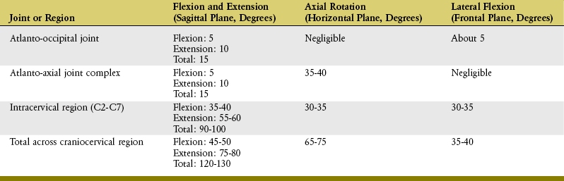
Osteokinematics of Flexion and Extension: About 120 to 130 degrees of combined flexion and extension occur across the entire craniocervical region. From the neutral position of about 30 to 35 degrees of extension (resting lordosis), the craniocervical region extends some additional 75 to 80 degrees and flexes 45 to 50 degrees (Figures 9-45 and 9-46). Extension exceeds flexion throughout the craniocervical region, on average by a margin of just over 1.5 to 1.
In addition to muscles, connective tissues limit the extremes of craniocervical motion. For example, the ligamentum nuchae and interspinous ligaments provide significant restraint to the extremes of flexion, whereas the approximation of the apophyseal joints limits the extremes of extension.163 Flexion is also limited by compression forces from the anterior margin of the annulus fibrosus, whereas extension is limited by the compression forces from the posterior margin of the annulus fibrosus. Additional tissues that limit or restrict sagittal plane motion across the craniocervical region are listed in Table 9-6.
About 20% to 25% of the total sagittal plane motion at the craniocervical region occurs over the atlanto-occipital joint and atlanto-axial joint complex, and the remainder occurs over the apophyseal joints of C2 to C7.147 The axis of rotation for flexion and extension is directed in a medial-lateral direction through each of the three joint regions: near the occipital condyles at the atlanto-occipital joint, the dens at the atlanto-axial joint complex, and the bodies or adjacent interbody joints of C2 to C7.34,56
The volume of the cervical vertebral canal is greatest in full flexion and least in full extension.87 For this reason, a person with stenosis (narrowing) of the vertebral canal may be more vulnerable to spinal cord injury during hyperextension activities. Repeated episodes of hyperextension-related injuries may lead to cervical myelopathy (from the Greek root myelo, denoting spinal cord, and pathos, suffering) and related neurologic deficits.
Arthrokinematics of Flexion and Extension:
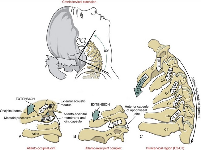
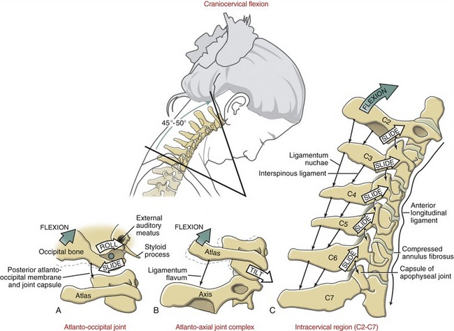
Atlanto-occipital Joint: Like the rockers on a rocking chair, the convex occipital condyles roll backward in extension and forward in flexion within the concave superior articular facets of the atlas. Based on traditional convex-on-concave arthrokinematics, the condyles are expected to simultaneously slide slightly in the direction opposite to the roll (see Figure 9-45, A and Figure 9-46, A). Tension in articular capsules, associated atlanto-occipital membranes, and alar ligaments limits the extent of the arthrokinematics.
Atlanto-axial Joint Complex: Although the primary motion at the atlanto-axial joint complex is axial rotation, the joint structure allows about 15 degrees of total flexion and extension. Acting as a spacer between the cranium and axis, the ring-shaped atlas tilts forward during flexion and backward during extension (see Figure 9-45, B and Figure 9-46, B). The extent of the tilting is limited, in part, by contact between the transverse ligament of the atlas and dens (at full flexion) and anterior arch of the atlas and dens (at full extension).
Intracervical Articulations (C2 to C7): Flexion and extension throughout the C2 to C7 vertebrae occur about an arc that follows the oblique plane set by the articular facets of the apophyseal joints. During extension the inferior articular facets of superior vertebrae slide inferiorly and posteriorly, relative to the superior articular facets of the inferior vertebrae (see Figure 9-45, C). These movements produce approximately 55 to 60 degrees of extension.
The arthrokinematics of flexion throughout the intracervical region occur in a reverse fashion to that described for extension. The inferior articular facets of the superior vertebrae slide superiorly and anteriorly, relative to the superior articular facets of the inferior vertebrae. As depicted in Figure 9-46, C, the sliding between the articular facets produces approximately 35 to 40 degrees of flexion. Flexion stretches the capsule of the apophyseal joints and reduces the area of joint contact.
Overall, about 90 to 100 degrees of cervical flexion and extension occur as a result of the sliding within the cervical apophyseal joint surfaces. This extensive range of motion is in part a result of the relatively long and unobstructed arc of motion provided by the oblique plane of the facet surfaces. On average, about 15 degrees of sagittal plane motion occur at each intervertebral junction between C2-C3 and C7-T1. The largest sagittal plane angular displacement tends to occur at the C4-C5 or C5-C6 levels,87,181 possibly accounting for the relatively high incidence of spondylosis and hyperflexion-related fractures at this level.
Osteokinematics of Protraction and Retraction: In addition to flexion and extension in the craniocervical region, the head can also translate forward (protraction) and backward (retraction) within the sagittal plane.148 As indicated in Figure 9-47, from a neutral position, full range of protraction naturally exceeds full range of retraction by about 80% (6.23 cm versus 3.34 cm in the normal adult, respectively).58 The neutral position is about 35% forward from the fully retracted position.
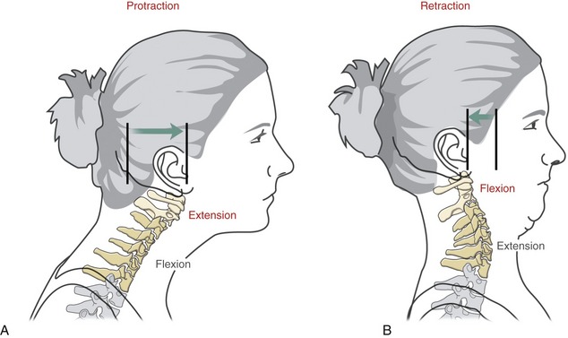
Typically, protraction of the head flexes the lower-to-mid cervical spine and simultaneously extends the upper craniocervical region (see Figure 9-47, A). Retraction of the head, in contrast, extends or straightens the lower-to-mid cervical spine and simultaneously flexes the upper craniocervical region (see Figure 9-47, B). In both movements, the lower-to-mid cervical spine follows the translation of the head. Protraction and retraction of the head are physiologically normal and useful motions, often associated with enhancing vision. Prolonged periods of protraction, however, may lead to a chronic forward head posture, causing increased strain on the craniocervical extensor muscles.
HORIZONTAL PLANE KINEMATICS
Osteokinematics of Axial Rotation: Axial rotation of the head and neck is a very important function, intimately related to vision and hearing. The full range of craniocervical rotation is about 65 to 75 degrees but varies considerably with age.197 Figure 9-48 shows a young person with about 80 degrees of active rotation to one side, for a total bilateral range of about 160 degrees. With an additional 160 to 170 degrees of total horizontal plane movement of the eyes, her bilateral visual field approaches 330 degrees, with little or no movement of the trunk.
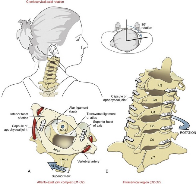
FIGURE 9-48. Kinematics of craniocervical axial rotation. A, Atlanto-axial joint complex. B, Intracervical region (C2 to C7).
About half the axial rotation of the craniocervical region occurs at the atlanto-axial joint complex, with the remaining throughout C2 to C7.226 Rotation at the atlanto-occipital joint is restricted because of the deep-seated placement of the occipital condyles within the superior articular facets of the atlas.
Arthrokinematics of Axial Rotation:
Atlanto-axial Joint Complex: The atlanto-axial joint complex is designed for maximal rotation within the horizontal plane. The design is most evident in the structure of the axis, with its vertical dens and near-horizontal superior articular facets (see Figure 9-32). The ring-shaped atlas and attached transverse ligament “twist” about the dens, producing about 35 to 40 degrees of axial rotation in each direction (see Figure 9-48, A). The generally flat inferior articular facets of the atlas slide in a curved path across the broad “shoulders” of the superior articular facets of the axis. Because of the limited axial rotation permitted at the atlanto-occipital joint, the cranium follows the rotation of the atlas nearly degree for degree. The axis of rotation for the head-and-atlas is provided by the vertically projected dens.
The extremes of axial rotation are limited primarily by contralaterally located alar ligaments, ligamentous tension in the apophyseal joints, and the many muscles that cross the craniocervical region (see Chapter 10). Full rotation stretches both vertebral arteries (see Figure 9-48, A).
Intracervical Articulations (C2 to C7): Rotation throughout C2 to C7 is guided primarily by the spatial orientation of the facet surfaces within the apophyseal joints. The facet surfaces are oriented about 45 degrees between the horizontal and frontal planes (see Figure 9-32). The inferior facets slide posteriorly and slightly inferiorly on the same side as the rotation, and anteriorly and slightly superiorly on the side opposite the rotation (see Figure 9-48, B). Approximately 30 to 35 degrees of axial rotation occur to each side over the C2 to C7 region, nearly equal to that permitted at the atlanto-axial joint complex. Rotation is greatest in the more cranial vertebral segments.
FRONTAL PLANE KINEMATICS
Osteokinematics of Lateral Flexion: Approximately 35 to 40 degrees of lateral flexion are available to each side throughout the craniocervical region (Figure 9-49). The extremes of this movement can be demonstrated by attempting to touch the ear to the tip of the shoulder. Most of this movement occurs at the C2 to C7 region; however, about 5 degrees may occur at the atlanto-occipital joint. Lateral flexion at the atlanto-axial joint complex is negligible.
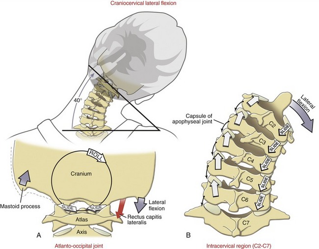
Arthrokinematics of Lateral Flexion:
Atlanto-occipital Joint: A small amount of side-to-side rolling of the occipital condyles occurs over the superior articular facets of the atlas. Based on the convex-on-concave relationship of the joints, the occipital condyles are expected to slide slightly in a direction opposite to the roll (see Figure 9-49, A).
Intracervical Articulations (C2 to C7): The arthrokinematics of lateral flexion at the C2 to C7 vertebral segments are illustrated in Figure 9-49, B. The inferior articular facets on the side of the lateral flexion slide inferiorly and slightly posteriorly, and the inferior articular facets on the side opposite the lateral flexion slide superiorly and slightly anteriorly.
SPINAL COUPLING BETWEEN LATERAL FLEXION AND AXIAL ROTATION
The approximate 45-degree inclination of the articular facets of C2 to C7 dictates a mechanical spinal coupling between movements in the frontal and horizontal planes. Because an upper vertebra follows the plane of the articular facet of a lower vertebra, a component of lateral flexion and axial rotation occur simultaneously. For this reason, lateral flexion and axial rotation in the mid-and-low cervical region are mechanically coupled in an ipsilateral fashion; for example, lateral flexion to the right occurs with slight axial rotation to the right, and vice versa.92
The ipsilateral spinal coupling just described for the mid-to-lower craniocervical region is the most well accepted and least controversial coupling pattern of the entire vertebral column.41 Although a few exceptions exist, this pattern has been documented using careful measurements, such as three-dimensional MRI. On casual visual observation, however, this coupling pattern is not so apparent. When asked, most persons appear to laterally flex the craniocervical region without an obligatory axial rotation of the face (or chin) to the side of the lateral flexion, or vice versa. The lack of a perceptible ipsilateral coupling is achieved by independent actions of either the atlanto-axial or atlanto-occipital joints. Consider, for instance, lateral flexion of C2 to C7 to the right. During this active motion, the atlanto-axial joint typically demonstrates a contralateral spinal coupling pattern by slightly rotating the atlas-and-cranium to the left, which conceals the fact that the C2 to C7 region actually rotated to the right.92,93 This compensatory action of the atlanto-axial joint minimizes the overall rotation of the head, which helps the eyes fixate on a stationary object during lateral flexion of the neck.
For reasons similar to those discussed in the previous paragraph, a compensatory contralateral coupling pattern usually also exists at the atlanto-occipital joints. This coupling minimizes any undesired lateral flexion of the head during axial rotation of the neck.92,93 The contralateral coupling patterns expressed at both atlanto-axial and atlanto-occipital joints are controlled subconsciously by the actions of specialized muscles. This topic is addressed further in Chapter 10.
SPECIAL FOCUS 9-5  Cervical Motion and Its Effect on the Diameter of the Intervertebral Foramina
Movement in the cervical region significantly affects the size of the intervertebral foramina. The difference in size can be large, especially during motions of flexion and extension.104 This issue has important clinical implications because of the location of the exiting spinal nerve roots. Magnetic resonance imaging has shown that from a neutral position, 40 degrees of flexion increases the area of a cervical intervertebral foramen by 31%; extension to 30 degrees, in contrast, decreases the area by 20%.137 The mechanical association between flexion and increased area in the C3-C4 intervertebral foramen can be appreciated by comparing the neutral position (Figure 9-50, A) with an extreme flexed position, shown in Figure 9-50, B. During flexion, an upward and forward slide of the inferior articular facet of C3 significantly widens the C3-C4 intervertebral foramen. Full flexion, therefore, allows greater room for passage of a spinal nerve root.
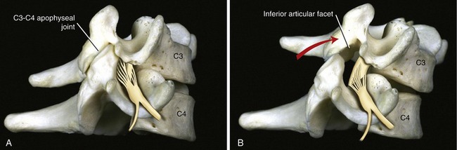
Thoracic Region
The thorax consists of a relatively rigid rib cage, formed by the ribs, thoracic vertebrae, and sternum. The rigidity of the region provides (1) a stable base for muscles to control the craniocervical region, (2) protection for the intrathoracic organs, and (3) a mechanical bellows for breathing (see Chapter 11).
ANATOMY OF THORACIC ARTICULAR STRUCTURES
The thoracic spine has 24 apophyseal joints, 12 on each side. Each joint possesses articular facets that face generally in the frontal plane, with a mild forward slope that averages about 15 to 25 degrees from the vertical (see example of T4 in Figure 9-32).124,150 The movement potential of these apophyseal joints is limited by the relative immobility of the adjacent costocorporeal and costotransverse joints. Indirectly, this pair of joints mechanically links most of the thoracic vertebrae anteriorly to the fixed sternum.
Most costocorporeal joints connect the head of a rib with a pair of costal demifacets on thoracic vertebral bodies and with the adjacent margin of an intervening intervertebral disc (Figure 9-51). The articular surfaces of the costocorporeal joints are slightly ovoid,188 held together primarily by capsular and radiate ligaments.
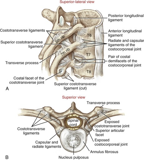
Costotransverse joints connect the articular tubercle of most ribs to the costal facet on the transverse process of the corresponding thoracic vertebrae. An articular capsule surrounds this synovial joint. The extensive (nearly 2 cm long) costotransverse ligament firmly anchors the neck of a rib to the entire length of a corresponding transverse process (see Figure 9-51). In addition, each costotransverse joint is stabilized by a superior costotransverse ligament. This strong ligament attaches between the superior margin of the neck of one rib and the inferior margin of the transverse process of the vertebra located above (see Figure 9-51, A). Ribs 11 and 12 usually lack costotransverse joints.
Because the ribs attach to the thoracic vertebrae, the kinematics of the thorax and the costocorporeal and costotransverse joints must be mechanically related, although this topic has not been rigorously studied. This text focuses on the kinematics of the costocorporeal and costotransverse joints as they relate to ventilation in Chapter 11.
With the exception of the sacroiliac joints, the thoracic region as a whole is normally the most mechanically stable portion of the vertebral column. Much of this inherent stability is afforded through attachments between the thoracic vertebrae and the rib cage. The constituents of the rib cage include the costocorporeal and costotransverse joints, ribs, sternocostal joints, and the sternum. In a study using cadavers, Watkins and colleagues showed that the rib cage (including the sternum) provides 20% to 40% of the total passive resistance against full thoracic motion.215 This resistance, however, does not include additional factors that exist in the living, such as volitionally increasing intra-abdominal pressure (via a Valsalva maneuver) and activating intercostal and trunk muscles. Nevertheless, the presence of an intact and stable rib cage protects the thoracic spine, including the spinal cord. During a fall, for example, the impact to the thoracic spine is partially absorbed and dissipated by the rib cage and the associated muscles and connective tissues. Evidence for this can be found by the relatively high frequency of fractures of the sternum that occur in combination with thoracic spine injuries.215
KINEMATICS
When an adult is standing, the thoracic region typically exhibits about 40 to 45 degrees of natural kyphosis.121 From the neutral position, motion occurs in all three planes. Although the range of motion at each thoracic intervertebral junction is relatively small, cumulative motion is considerable when expressed over the entire thoracic spine (Table 9-8). Few consistent and reliable data could be found in the literature that describe the three-dimensional kinematics in the thoracic region.121 The values presented in Table 9-8, therefore, are based partially on visual observation.
TABLE 9-8.
Approximate Range of Motion for the Three Planes of Movement for the Thoracic Region
| Flexion and Extension (Sagittal Plane, Degrees) | Axial Rotation (Horizontal Plane, Degrees) | Lateral Flexion (Frontal Plane, Degrees) |
| Flexion: 30-40 Extension: 20-25 Total: 50-65 |
30-35 | 25-30 |
Kinematics of Flexion and Extension: Approximately 30 to 40 degrees of flexion and 20 to 25 degrees of extension are available throughout the thoracic region. These kinematics are shown in context with flexion and extension over the entire thoracolumbar region in Figures 9-52 and 9-53, respectively. The extremes of flexion are limited by tension in connective tissues located posterior to the vertebral bodies, including the capsule of the apophyseal joints and supraspinous and posterior longitudinal ligaments. The extremes of extension, on the other hand, are limited by tension in the anterior longitudinal ligament and by potential impingement between laminae or between adjacent downward-sloping spinous processes, especially in the upper and middle thoracic vertebrae. The magnitude of thoracic flexion and extension is greater in the extreme caudal regions, in great part because of the “free-floating” most caudal ribs and the shift to a more sagittal plane orientation of the apophyseal joints.124,182
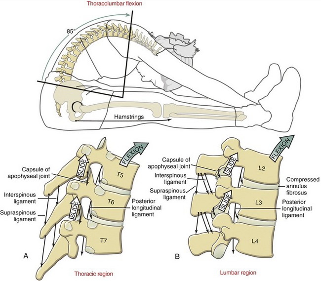
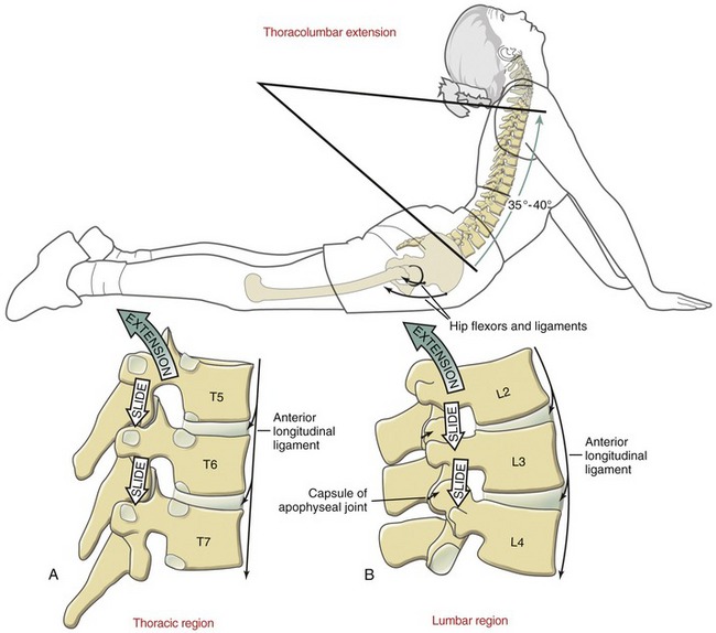
The arthrokinematics at the apophyseal joints in the thoracic spine are generally similar to those described for the C2 to C7 region. Subtle differences are related primarily to different shapes of the vertebrae, rib attachments, and different spatial orientations of the articular facets of apophyseal joints. Flexion between T5 and T6, for example, occurs by a superior and slightly anterior sliding of the inferior facet surfaces of T5 on the superior facet surfaces of T6 (see Figure 9-52, A). The moderately forward-sloped articular surfaces of the apophyseal joints naturally facilitate flexion throughout the region. Extension occurs by a reverse process (see Figure 9-53, A).
Kinematics of Axial Rotation: Approximately 30 to 35 degrees of horizontal plane (axial) rotation occur to each side throughout the thoracic region. This motion is depicted in conjunction with axial rotation across the entire thoracolumbar region in Figure 9-54. Rotation between T6 and T7, for instance, occurs as the near–frontal plane–aligned inferior articular facets of T6 slide for a short distance against the similarly aligned superior articular facets of T7 (see Figure 9-54, A). The freedom of axial rotation declines in lower regions of the thoracic spine. In this region, the apophyseal joints are slightly more vertically oriented as they shift to a more sagittal plane orientation.124,182
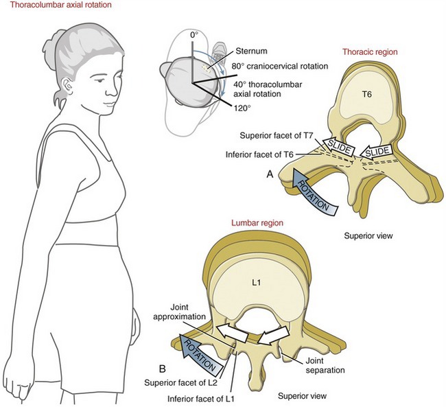
Kinematics of Lateral Flexion: The predominant frontal plane orientation of the thoracic facet surfaces suggests a relative freedom of lateral flexion. This potential for movement is never fully expressed, however, because of the stabilization provided by the attachments to the ribs. Lateral flexion in the thoracic region is illustrated in context with lateral flexion over the entire thoracolumbar region in Figure 9-55. Approximately 25 to 30 degrees of lateral flexion occur to each side in the thoracic region. As depicted in Figure 9-55, A, lateral flexion of T6 on T7 occurs as the inferior facet surface of T6 slides superiorly on the side contralateral to the lateral flexion and inferiorly on the side ipsilateral to the lateral flexion. Note that the ribs drop slightly on the side of the lateral flexion and rise slightly on the side opposite the lateral flexion.
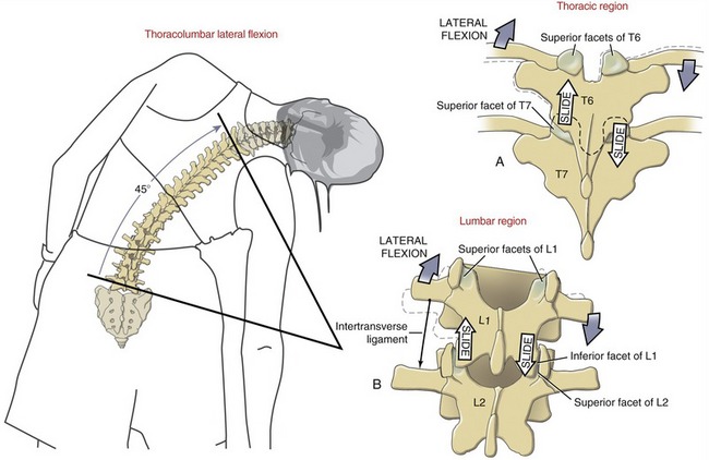
Lumbar Region
ANATOMY OF THE ARTICULAR STRUCTURES
L1 to L4 Region: The facet surfaces of most lumbar apophyseal joints are oriented nearly vertically, with a moderate-to-strong sagittal plane bias (Figure 9-56). The orientation of the superior articular facet of L2, for example, is on average about 25 degrees from the sagittal plane (see Figure 9-32). This orientation favors sagittal plane motion at the expense of rotation in the horizontal plane.
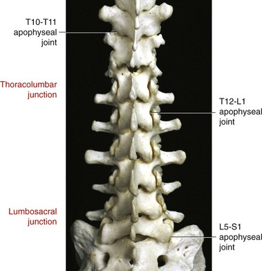
SPECIAL FOCUS 9-6  Some Clinical Implications Regarding the Thoracolumbar Junction
At or near the thoracolumbar junction, the facet surfaces of the apophyseal joints change their orientation rather abruptly, from near-frontal to near-sagittal planes.124 The exact point of this transition is variable, often starting one or two junctions cranialward, as shown in the specimen illustrated in Figure 9-56. This relative sharp frontal-to-sagittal plane transition in apophyseal joint orientation may create a sagittal plane hypermobility and instability in this region. This is evident in Figure 9-57 as a young boy with cerebral palsy attempts to support himself up on his knees. The lack of control and weakness of his trunk muscles allows the thoracolumbar junction to collapse into the plane of least bony resistance—in this case, into marked thoracolumbar hyperextension. This collapse creates a severe hyperlordosis in the region.
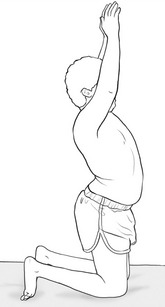
L5-S1 Junction: As any typical intervertebral junction, the L5-S1 junction has an interbody joint anteriorly and a pair of apophyseal joints posteriorly. The facet surfaces of the L5-S1 apophyseal joints are usually oriented in a more frontal plane than those of other lumbar regions (see Figure 9-56).
The base (top) of the sacrum is naturally inclined anteriorly and inferiorly, forming an approximate 40-degree sacrohorizontal angle when one is standing (Figure 9-58, A).106 Given this angle, the resultant force resulting from body weight (BW) creates an anterior shear force (BWS), and a compressive force (BWC) acting perpendicular to the superior surface of the sacrum. The magnitude of the anterior shear is equal to the product of BW times the sine of the sacrohorizontal angle. A typical sacrohorizontal angle of 40 degrees produces an anterior shear force at the L5-S1 junction equal to 64% of superimposed BW. Increasing the degree of lumbar lordosis enlarges the sacrohorizontal angle, which in effect increases the anterior shear at the L5-S1 junction. If the sacrohorizontal angle were increased to 55 degrees, for example, the anterior shear force would increase to 82% of superimposed BW. During standing or sitting, lumbar lordosis can be increased by this amount by anterior tilting of the pelvis (see Figure 9-63, A). (Tilting the pelvis is defined as a short-arc sagittal plane rotation of the pelvis relative to both femoral heads. The direction of the tilt is indicated by the direction of rotation of the iliac crests.)
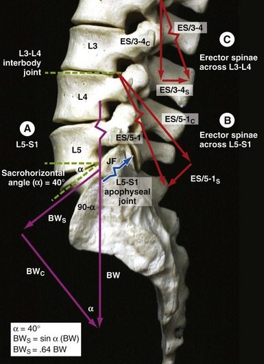
Several structures resist the natural anterior shearing force produced at the L5-S1 junction. The wide and strong anterior longitudinal ligament crosses anterior to the L5-S1 junction. The iliolumbar ligament arises from the inferior aspect of the transverse processes of L4-L5 and adjacent fibers of the quadratus lumborum muscle. The ligament attaches inferiorly to the ilium, just anterior to the sacroiliac joint, and to the upper-lateral aspect of the sacrum (see Figure 9-70). Bilaterally, the iliolumbar ligaments provide a firm anchor between the naturally stout transverse processes of L5 and the underlying ilium and sacrum.23,72,224
In addition to the aforementioned connective tissues, the wide, sturdy articular facets of the L5-S1 apophyseal joints provide bony stabilization to the L5-S1 junction. The near–frontal plane inclination of the facet surfaces is ideal for resisting the anterior shear at this region. This resistance creates a compression force within the L5-S1 apophyseal joints (see blue force vector in Figure 9-58, A, labeled JF). Without adequate stabilization, the lower end of the lumbar region can slip forward relative to the sacrum.76 This abnormal, potentially serious condition is known as anterior spondylolisthesis.
SPECIAL FOCUS 9-7  Anterior Spondylolisthesis at L5-S1
Anterior spondylolisthesis is a general term that describes an anterior slipping or displacement of one vertebra relative to another. This condition often occurs at the L5-S1 junction, as illustrated in Figure 9-59. The term spondylolisthesis is derived from the Greek spondylo, meaning vertebra, and listhesis, meaning to slip. This condition may be acquired after excessive stress or pathology, or it may be congenital.207 Most often, an anterior spondylolisthesis in the lower lumbar region is associated with a bilateral fracture (or deficit) through the pars articularis, a section of a lumbar vertebra midway between the superior and inferior articular processes (see Figure 9-27). The acquired form of anterior spondylolisthesis at L5 and S1 may be progressive, in some cases caused by repetitive physical activities that involve hyperextension of the region. Severe cases of anterior spondylolisthesis may damage the cauda equina, as this bundle of nerves passes by the L5-S1 junction.
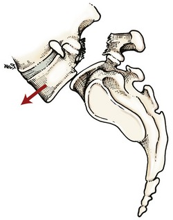
As described for Figure 9-58, A, increased lumbar lordosis increases the normal sacrohorizontal angle, thereby increasing the anterior shear force between L5 and S1. Exercises or other actions that create a forceful hyperextension of the lower lumbar spine are therefore contraindicated for persons with anterior spondylolisthesis, especially if the condition is unstable or progressive.207 As shown in Figure 9-58, B, the force vector of the erector spinae muscle that crosses L5-S1 (ES/5-1) creates an anterior shear force (ES/5-1S) parallel to the superior body of the sacrum. The direction of this shear is a function of the orientation of the adjacent erector spinae fibers and the 40-degree sacrohorizontal angle. In theory, a greater muscular force increases the anterior shear at the L5-S1 junction, especially if the muscle activation exaggerates the lordosis.
The anterior-directed shear forces produced by the lumbar erector spinae occur primarily at the L5-S1 junction and not, as a rule, throughout the entire lumbar region.102 As indicated in Figure 9-58, C, in normal posture the superior surfaces of the bodies of the middle lumbar vertebrae are typically positioned in a more horizontal orientation. The erector spinae muscle fibers that cross this region more likely produce a posterior shear across the lumbar interbody joints (see Figure 9-58, C, ES/3-4S).125 This muscle-produced shear may be physiologically useful, offering resistance to the anterior shear that may be produced during bending and lifting loads in front of the body.
KINEMATICS
While a healthy adult is standing, the lumbar spine typically exhibits about 40 to 50 degrees of lordosis,23,106 although a wide variation exists. From this neutral position, the lumbar spine can move in three degrees of freedom. Data on the range of lumbar motion are highly variable; typical values are listed in Table 9-9.* The following sections focus on the kinematics of each plane of motion within the lumbar region.
TABLE 9-9.
Approximate Range of Motion for the Three Planes of Movement for the Lumbar Region
| Flexion and Extension (Sagittal Plane, Degrees) | Axial Rotation (Horizontal Plane, Degrees) | Lateral Flexion (Frontal Plane, Degrees) |
| Flexion: 40-50 Extension: 15-20 Total: 55-70 |
5-7 | 20 |
Sagittal Plane Kinematics: Flexion and Extension: Although data vary considerably across studies and populations, about 40 to 50 degrees of flexion and 15 to 20 degrees of extension occur at the lumbar spine.144,152,153,198,213 The total 55- to 70-degree arc of sagittal plane motion is substantial, considering it occurs across only five intervertebral junctions. This predominance of sagittal plane motion is largely a result of the prevailing sagittal plane orientation of the facet surfaces of the lumbar apophyseal joints.
The following section of the chapter focuses on several subtopics within the broad topic of sagittal plane kinematics of the lumbar spine. Box 9-2 lists the order of these subtopics.
Flexion of the Lumbar Region: Figure 9-52, B shows the kinematics of flexion of the lumbar region in context with flexion of the trunk and hips. Pelvic-on-femoral (hip) flexion increases the passive tension in the stretched hamstring muscles. With the lower end of the vertebral column fixed by the sacroiliac joints, continued flexion of the middle and upper lumbar region reverses the natural lordosis in the low back.
During flexion between L2 and L3, for example, the inferior articular facets of L2 slide superiorly and anteriorly, relative to the superior facets of L3. As a consequence, compression forces from body weight are transferred away from the apophyseal joints (which normally support about 20% of the total spinal load in erect standing) and toward the discs and vertebral bodies.5,174 The compressed anterior aspects of the discs and stretched posterior ligaments support more of the total load as the trunk is progressively flexed. In extreme flexion the fully stretched articular capsules of the apophyseal joints restrain further forward migration of the superior vertebra.194
The degree of flexion of the lumbar spine significantly affects the diameter of each intervertebral foramen and the potential deformation of the nucleus pulposus. Relative to a neutral position, full flexion increases the diameter of the intervertebral foramen by 19%.90 Lumbar flexion therefore may be used therapeutically as a way to temporarily reduce the pressure on a lumbar spinal nerve root that is impinged on by an obstructed foramen.173 In certain circumstances, however, this potential therapeutic advantage may be associated with a potential therapeutic disadvantage. For example, excessive or prolonged flexion of the lumbar region generates increased compression force on the anterior side of the disc, ultimately deforming the gel-like nucleus pulposus in a posterior direction.* In the healthy spine the magnitude of the posterior deformation is small and usually of no consequence. Actual migration of the disc is normally resisted by increased tension in the stretched posterior side of the annulus fibrosus. A disc with a weak, cracked, or distended posterior annulus may, however, experience a posterior migration (or oozing) of the nucleus pulposus. In some cases the nuclear material may impinge against the spinal cord or nerve roots (Figure 9-60). This potentially painful impairment is frequently referred to as a herniated or prolapsed disc, or more formally a herniated nucleus pulposus. Persons with a herniated disc may experience pain or altered sensation, muscle weakness, and reduced reflexes in the lower extremity, consistent with the specific motor and sensory distribution of the impinged nerve root.
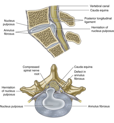
SPECIAL FOCUS 9-8  More about the Herniated Nucleus Pulposus
The formal name for a herniated or prolapsed disc is a herniated nucleus pulposus. Herniations typically involve a posterior-lateral or posterior migration of the nucleus pulposus toward the very sensitive neural tissues (i.e., the spinal cord, cauda equina, ventral or dorsal nerve roots, or exiting spinal nerve roots). Not all herniated discs are as remarkable as that illustrated in Figure 9-60.95 In relatively mild cases the displaced nucleus migrates posteriorly but remains well within the confines of the annulus fibrosus. More moderate cases, however, may progress to a point at which the nuclear material, although still remaining within the posterior annulus, bulges or protrudes beyond the circumference of the posterior rim of the vertebral body. In more severe cases this nuclear material completely herniates through the annular wall (or posterior longitudinal ligament) and extrudes into the epidural space (depicted in Figure 9-60). The extruded nuclear material may contain fragments of the degenerated annulus and vertebral endplates.220 In some cases the extruded material may become lodged in the epidural space—frequently referred to as sequestration of the herniated disc. Extruded or sequestered herniations may have a better prognosis than a protruded or bulging disc. Once displaced into the spinal canal, the herniated nucleus attracts macrophages that can assist with resorption of the displaced material.95
Disc-related pain may result from the degenerated disc itself or from consequences of a herniated nucleus pulposus. Pain associated with a degenerated disc may be from damage to the innervated periphery of the posterior annulus fibrosus, posterior longitudinal ligament, or vertebral endplates. Perhaps more serious, however, is the pain and radiculopathy caused by the herniated disc compressing the neural tissues within the spinal canal (as seen in Figure 9-60). In both scenarios, pain increases when the local tissues are inflamed.116 Compressed and inflamed nerves within the spinal canal or intervertebral foramina typically produce pain and altered sensations that are topographically associated with the dermatomes in the lower extremities. The symptoms are often referred to as “sciatica” because of the strong likelihood that the herniated disc affects nerve roots associated with the sciatic nerve (L4-S3). Although pain may be a large component of a herniated nucleus pulposus, it is not a universal consequence of the pathlogy.26
Posterior disc herniation in the lumbar region typically involves two often interrelated mechanisms. The first involves a large, sudden compression or shear force delivered against an otherwise relatively healthy lumbar spine. This mechanism of injury may be associated with a single traumatic event, such as extremely strenuous coughing or vomiting154 or the lifting of a very large load. A second and much more common mechanism involves a series of lower-magnitude forces delivered against the lumbar spine over the course of several years, most often involving preexisting disc degeneration.63,214 A degenerated disc may possess radial clefts (or fissures) that serve as a path of least resistance for the migration of the nuclear material.
Repetitive or chronic flexion of the lumbar spine increases the vulnerability of a posterior or posterior-lateral disc herniation. Flexion stretches and thins the posterior side of the annulus while the nuclear gel is forced posteriorly, often under high hydrostatic pressure. These pressures increase during strenuous lifting or bending activities that require strong activation of trunk muscles.138,175 With sufficiently high hydrostatic pressure, the nuclear gel can create or find a preexisting fissure in the posterior annulus.
Lumbar flexion combined with a twisting motion (i.e., axial rotation combined with lateral flexion) further increases the vulnerability of a posterior or posterior-lateral disc herniation.175,200 When the spine is rotated, only half the posterior fibers of the annulus are taut, reducing its resistance to the approaching nuclear gel. Computer modeling and cadaveric research have also shown that combined axial rotation and lateral flexion concentrate large circumferential tensions in the annular fibers located within the posterior-lateral quadrant of the disc.175,200 Over time, this region is more prone to develop fissures or cracks, thereby providing little resistance to the encroaching nuclear material.
It has been argued that a severely degenerated (and dehydrated) disc seldom experiences the classic herniated nucleus pulposus.29 Apparently, a dehydrated nucleus is too dry and not under sufficient hydrostatic pressure to flow through the annulus. Although exceptions certainly exist, the classic herniated nucleus pulposus tends to occur more frequently in persons under the age of about 40 years old, at a time when the nucleus is still able to retain a relatively large volume of water. Furthermore, the chance of experiencing a herniated disc tends to be greater in the morning, when the nucleus contains its greatest daily water content.15,118
Mechanical or Structural Factors That Favor a Herniated Nucleus Pulposus in the Lumbar Spine
1. Preexisting disc degeneration with radial fissures, cracks, or tears in the posterior annulus that allow a path for the flow of nuclear material
2. Sufficiently hydrated nucleus capable of exerting high intradiscal pressure
3. Inability of the posterior annulus to resist pressure from the migrating nucleus
4. Sustained or repetitive loading applied over a flexed and rotated spine
Extension of the Lumbar Region: Extension of the lumbar region is essentially the reverse kinematics of flexion, and it increases the natural lordosis (see Figure 9-53). When lumbar extension is combined with full hip extension, the increased passive tension in the stretched flexor muscles and capsular ligaments of the hip promotes lumbar lordosis by generating an anteriorly tilting force on the pelvis. Extension between L2 and L3, for example, occurs as the inferior articular facets of L2 slide inferiorly and slightly posteriorly relative to the superior facets of L3.
From a flexed position, moving into the neutral or slightly extended position increases the contact area within the apophyseal joints, at a time when these joints are typically accepting a greater percentage of body weight.174,179 This situation may help limit the contact pressure within the joints. This protective scenario does not apply, however, to the physiologic extremes of lumbar extension. In full lumbar hyperextension, the tips of the inferior articular facets (of a top vertebra) slide inferiorly beyond the joint surface of the superior articular facets of the vertebra below. Contact pressures can therefore be very high in the hyperextended lumbar spine as the relatively “sharp” tips of the inferior articular facet contact the adjacent lamina region. For this reason, a chronic posture of lumbar hyperlordosis can place large and potentially damaging stress on the apophyseal joints and adjacent regions. Furthermore, hyperextension of the lumbar spine can compress the interspinous ligaments, possibly creating a source of low-back pain.85
As with flexion, extension of the lumbar spine significantly affects the diameter of the intervertebral foramina and the potential for deforming the nucleus pulposus.9,67,176 Relative to the neutral position, full lumbar extension reduces the diameter of the intervertebral foramina by 11%.90 For this reason a person with nerve root impingement caused by a stenosed intervertebral foramen should limit activities that involve hyperextension, especially if they cause weakness or altered sensations in the extremities. Full extension, however, tends to deform the nucleus pulposus in an anterior direction,64,200 thereby potentially limiting the more typical posterior migration of the nucleus.9,18 Full sustained lumbar extension has been shown to reduce pressure within the disc138,175 and in some cases to reduce the contact pressure between the displaced nuclear material and the neural tissues. Evidence of the latter is often described as “centralization” of symptoms, meaning that the pain or altered sensation (formerly perceived in the lower extremities because of nerve root impingement) migrates toward the low back.55,217 Centralization therefore suggests reduced contact pressure between the displaced nuclear material and a nerve root. The reduced contact pressure after sustained full extension may occur because the nuclear material is pushed forward and away from the neural tissues, because the neural tissues are pulled posteriorly and away from the nuclear material, or both. Emphasizing lumbar extension exercises and postures as a way to reduce radiating pain and radiculopathy from a posterior herniated nucleus pulposus was popularized by Robin McKenzie, and such exercises are well known as “McKenzie exercises.”127 Therapeutic approaches that emphasize sustained active and passive extension have been shown to offer varying degrees of relief of symptoms and improvement of function in persons with a known posterior or posterior-lateral disc herniation.30,38 This one approach, however, is likely not beneficial for everyone with chronic low-back pain.119
Lumbopelvic Rhythm during Trunk Flexion and Extension: In conjunction with the hip joints, the lumbar spine provides the major flexion and extension pivot point for the human body as a whole. Consider, in this respect, activities such as forward and backward bending of the trunk, climbing a steep hill, and lifting objects from the ground. The kinematic relationship between the lumbar spine and hip joints during such sagittal plane movements has been referred to as lumbopelvic rhythm. (A loose analogy of this concept exists for the shoulder and was described as scapulohumeral rhythm in Chapter 5.) Paying attention to the lumbopelvic rhythm in persons with painful or labored movements may provide clues for detecting abnormal muscle and joint interactions within the region.110,134,180,196 These clues may provide insight into effective treatment for the underlying pathomechanics.
Variations of Lumbopelvic Rhythms during Trunk Flexion from a Standing Position: a Kinematic Analysis: Consider the common action of bending forward toward the ground while keeping the knees nearly straight. This motion in the healthy adult has been measured as a combination of about 40 degrees of lumbar flexion performed nearly simultaneously with about 70 degrees of hip (pelvic-on-femoral) flexion (Figure 9-61, A).60 Although other kinematic strategies are likely, those which deviate significantly from this pattern may help distinguish pathology or impairments affecting the lower spine from those affecting the hip joints.
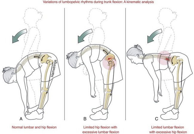
Figure 9-61, B and C shows abnormal lumbopelvic rhythms associated with marked restriction in mobility at the hip joints (B) or lumbar region (C). In both B and C, the amount of overall trunk flexion is reduced. If greater trunk flexion is required, the hip joints or lumbar region may mutually compensate for the other’s limited mobility. This situation may increase the stress on the compensating region. As depicted in Figure 9-61, B, with limited hip flexion from, for example, restricted hamstring extensibility, bending the trunk toward the floor requires greater flexion in the lumbar and lower thoracic spinal regions. Eventually, exaggerated flexion may overstretch and subsequently weaken the posterior connective tissues within the region (including the thoracolumbar fascia), thereby reducing the ability of these tissues to limit further flexion. A chronic posture of increased flexion of the lumbar spine places a disproportionally larger compressive load on the intervertebral discs, theoretically increasing their likelihood for degeneration.
Figure 9-61, C demonstrates a kinematic scenario where flexion of the lumbar spine is limited. Reaching toward the floor requires disproportionally greater flexion of the hips, thereby creating greater demands on the hip extensor muscles. As a consequence, the hip joints are subjected to greater compression loads. In persons with healthy hips, this relatively low-level increase in compression force is usually well tolerated. In a person with a preexisting hip condition (such as osteoarthritis or hip instability), however, the increased compression force may be painful and possibly accelerate a degenerative process.
Lumbopelvic Rhythm during Trunk Extension from a Forward Bent Position: a Muscular Analysis: The typical lumbopelvic rhythm used to extend the trunk from a forward bent position is depicted in a series of consecutive phases in Figure 9-62, A to C. Extension of the trunk with knees extended is often initiated by extension of the hip joints (see Figure 9-62, A). This is usually followed after a short delay by extension of the lumbar spine (see Figure 9-62, B to C).141 This short delay in lumbar extension places greater extension torque demands on the powerful hip extensor muscles (such as the hamstrings and gluteus maximus) at the time when the external flexion torque on the lumbar region is greatest (see external moment arm depicted as a dark black line in Figure 9-62, A). This may be a beneficial strategy to naturally protect the low-back muscles and joints from large forces. In this scenario, the demand on the lumbar extensor muscles increases only after the trunk has been sufficiently raised and the external moment arm, relative to body weight, has been minimized (see Figure 9-62, B). Persons with low-back pain or existing degenerative conditions may purposely further delay strong activation of the lumbar extensor muscles until the trunk is nearly vertical. Once standing fully upright, hip and back muscles are typically relatively inactive, as long as the force vector resulting from body weight falls posterior to the hip joints (see Figure 9-62, C).
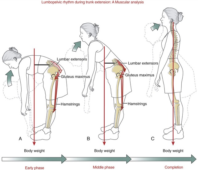
Effect of Pelvic Tilting on the Kinematics of the Lumbar Spine: Flexion and extension of the lumbar spine typically occur by one of two fundamentally different movement strategies. The first strategy is often used to maximally displace the upper trunk and upper extremities relative to the thighs, such as when lifting or reaching. This strategy, depicted in Figures 9-61, A and 9-62, combines near maximal flexion and extension of the lumbar spine with a wide arc of pelvic-on-femoral (hip) and trunk motion. A second, more subtle movement strategy involves a relatively short-arc forward or backward tilt (or rotation) of the pelvis, with the trunk remaining nearly stationary. As depicted in Figure 9-63, A to D, an anterior pelvic tilt accentuates lumbar lordosis, whereas a posterior pelvic tilt reduces lumbar lordosis.112 The extremes of these postures can significantly alter the diameter of the lumbar vertebral canal and intervertebral foramina and create a pressure gradient that may deform or push the nucleus pulposus slightly—in a direction away from the compressed side of the disc.
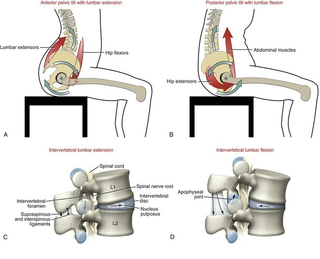
The axis of rotation for pelvic tilting is in a medial-lateral direction through both hip joints. This mechanical association strongly links the (pelvic-on-femoral) movement of the hip joints with that of the lumbar spine. This relationship is discussed further in the next section and again in Chapter 12.
Kinesiologic Correlations between Anterior Pelvic Tilt and Increased Lumbar Lordosis: Active anterior pelvic tilt is caused by contraction of the hip flexor and back extensor muscles (see Figure 9-63, A). Strengthening and increasing the postural control of these muscles, in theory, favors a more lordotic posture of the lumbar spine.173 Whether a person can subconsciously adopt and maintain a newly learned pelvic posture over an extended period is uncertain. Nevertheless, maintaining the natural lordotic posture in the lumbar spine is a fundamental principle espoused by McKenzie for some persons with a posteriorly herniated nucleus pulposus.127
The lumbar region may demonstrate greatly exaggerated lordosis that is physiologically undesirable. This could be caused by muscle weakness, such as weakness of the hip extensor and abdominal muscles in a child with severe muscular dystrophy. The pathomechanics of exaggerated lumbar lordosis often involve a hip flexion contracture with increased passive tension (tightness) in the hip flexor muscles (Figure 9-64).75 As described earlier in this chapter, possible negative consequences of exaggerated lordosis include increased compression within the lumbar apophyseal joints or increased contact pressure between posterior elements of lumbar vertebrae.179 Furthermore, exaggerated lumbar lordosis is associated with an increased anterior shear force at the lumbosacral junction and, in some persons, possibly favoring the development of an anterior spondylolisthesis.
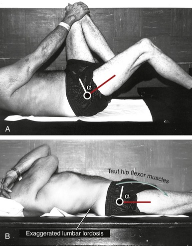
Kinesiologic Correlations between Posterior Pelvic Tilt and Decreased Lumbar Lordosis: Active posterior pelvic tilt is produced by contraction of the hip extensor and abdominal muscles (see Figure 9-63, B). Strengthening and increasing the patient’s conscious control over these muscles theoretically favor a reduced lumbar lordosis. This concept was the trademark of the once popular “Williams flexion exercises,” a therapeutic approach that stressed stretching the hip flexor and low-back extensor muscles while strengthening the abdominal and hip extensor muscles.221 In principle, these exercises were considered most appropriate for persons with low-back pain caused by excessive lumbar lordosis. As previously described, exaggerated lumbar lordosis increases the sacrohorizontal angle, which may predispose a person to an anterior spondylolisthesis of the lower lumbar region.
SPECIAL FOCUS 9-9  Using Knowledge of Kinesiology to Help Guide Treatment of Chronic Low-Back Pain: a Selected Example
There are many nonsurgical, therapeutic approaches for treating persons with chronic low-back pain. One reason for the many differing approaches is the frequent lack of understanding of the exact mechanical dysfunction, pathology, and underlying cause of the pain. Pain in the low back can stem from multiple anatomic sources, including muscle, bone, superficial regions of the intervertebral disc, spinal nerve root or spinal cord impingement, ligament, dura mater, fascia, or apophyseal and sacroiliac joints. Treatment approaches also vary based on the formal training, clinical experience, and theoretic and philosophical background of the clinician. Some clinicians direct their nonsurgical treatment for low-back pain based primarily on pathoanatomic or mechanical-based models. Others, however, rely more on classifying, or subgrouping, their patients based on clusters of examination findings that have been shown to favorably respond to a given therapeutic approach.30,39,71,195
A thorough discussion of the various physical therapy approaches to chronic low-back pain is not within the scope of this chapter. In short, however, approaches include training to improve the strength and control of muscles, selective activation and stretching of muscles and connective tissues to optimize vertebral movement and alignment,161 advice on modifying posture or design of the workplace, mobilization and manipulation,10 traction, soft-tissue massage, and physical modalities (e.g., heat, electrical stimulation, and therapeutic ultrasound). Many approaches associated with the treatment (as well as diagnosis) of low-back pain involve movement of the lumbar region. For this reason the clinician must understand the associated kinesiology. To highlight one example of this point, consider the marked and usually contrasting biomechanical effects that are associated with flexion and extension of the lumbar intervertebral junctions (Table 9-10). The contrasting biomechanics can give important clues as far as the source of pain or mechanical dysfunction, and ultimately the most effective treatment.
TABLE 9-10.
Some Contrasting Kinesiologic Effects of Lumbar Flexion and Extension
| Structure | Effect of Flexion | Effect of Extension |
| Nucleus pulposus | Deformed or pushed posteriorly | Deformed or pushed anteriorly |
| Annulus fibrosus | Posterior side stretched | Anterior side stretched |
| Apophyseal joint | Capsule stretched Minimizes articular contact area Articular loading decreased |
Capsule slackened (neutral extension only) Maximizes articular contact area (neutral extension only) Articular loading increased |
| Intervertebral foramen | Widened | Narrowed |
| Posterior longitudinal ligament | Increased tension (elongated) | Decreased tension (slackened) |
| Ligamentum flavum | Increased tension (elongated) | Decreased tension (slackened) |
| Interspinous ligament | Increased tension (elongated) | Decreased tension (slackened) |
| Supraspinous ligament | Increased tension (elongated) | Decreased tension (slackened) |
| Anterior longitudinal ligament | Decreased tension (slackened) | Increased tension (elongated) |
| Spinal cord | Increased tension (elongated) | Decreased tension (slackened) |
Horizontal Plane Kinematics: Axial Rotation: Only about 5 to 7 degrees of horizontal plane rotation occur to each side throughout the lumbar region.151,198 Clinical measurements often exceed this amount, likely because of extraneous motion at the hip joint (pelvis rotating on the femur) and the lower thoracic region.144 The 5 to 7 degrees of rotation are shown in context with the rotation of the thoracolumbar region in Figure 9-54, B. Axial rotation between L1 and L2 to the right, for instance, occurs as the left inferior articular facet of L1 approximates or compresses against the left superior articular facet of L2. Simultaneously, the right inferior articular facet of L1 separates (distracts) slightly from the right superior articular facet of L2.
The limited amount of axial rotation permitted within the lumbar region is remarkable. Just over 1 degree of unilateral axial rotation has been measured at the L3-L4 intervertebral junction.189 The relatively strong sagittal plane orientation of the lumbar apophyseal joints physically restrict axial rotation. As indicated in Figure 9-54, B, the apophyseal joints located contralateral to the side of the rotation compress (or approximate), thereby blocking further movement. Much of the actual rotation is accompanied by compression of the articular cartilage within the contralateral apophyseal joint. (Recall that the direction of rotation of any part of the axial skeleton is based on a point on the anterior side of the region, not the spinous process.) Axial rotation is also restricted by tension created in the stretched annulus fibrosus.107 In theory, an axial rotation of 3 degrees at any lumbar intervertebral junction would damage the articular facet surfaces and tear the collagen fibers in the annulus fibrosus.23 Most normal physiologic movements remain safely under this potentially damaging limit.
Frontal Plane Kinematics: Lateral Flexion: About 20 degrees of lateral flexion occur to each side in the lumbar region.151,198,213 Except for differences in orientation and structure of the apophyseal joints, the arthrokinematics of lateral flexion are nearly the same in the lumbar region as in the thoracic region. Ligaments on the side opposite the lateral flexion limit the motion (see Figure 9-55, B). Normally the nucleus pulposus deforms slightly away from the direction of the movement, or, stated differently, toward the convex side of the bend.200
Sitting Posture and Its Effect on Alignment within the Lumbar and Craniocervical Regions: For many persons a great deal of time is spent sitting—at work, at school, at home, or in a vehicle. The posture of the pelvis during sitting can have a substantial influence on the spinal alignment throughout the vertebral column. The topic of sitting posture therefore has important therapeutic implications on the treatment and prevention of problems throughout the axial skeleton. The following discussion highlights the effects of sagittal plane posturing of the pelvis, specifically as it affects the lumbar and craniocervical regions.
Consider the classic contrast made between “poor” and “ideal” sitting postures (Figure 9-65). In the poor or slouched posture depicted in Figure 9-65, A, the pelvis is posteriorly tilted with a relatively flexed (flattened) lumbar spine. Eventually this posture may lead to adaptive shortening in connective tissues and muscles, ultimately perpetuating the undesirable posture.
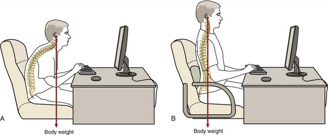
A slouched sitting posture increases the external moment arm between the line of force of the upper body and lumbar vertebrae (see red line in Figure 9-65, A). This situation places greater demands on tissues that normally resist flexion of the lower trunk, including the intervertebral discs. As explained earlier in this chapter, in vivo pressure measurements typically demonstrate larger pressures within the lumbar discs in slouched sitting compared with erect sitting.219 Even in healthy persons, the increased pressures from the slouched sitting position can deform the nucleus pulposus posteriorly slightly, especially in the L4-L5 and L5-S1 regions.9 A habitually slouched sitting posture may, in time, overstretch and thus weaken the posterior annulus fibrosus, reducing its ability to block a posteriorly protruding nucleus pulposus. This biomechanical scenario may be related to the pathogenesis of a significant number of cases of nonspecific low-back pain.9 The position of the pelvis and lumbar spine during sitting strongly influences the posture of the axial skeleton as far cranially as the craniocervical region.128 On average, the flat posture of the low back is associated with a more protracted position of the craniocervical region (i.e., a “forward head” posture) (see Figure 9-65, A).22 Sitting with the lumbar spine flexed tips the thoracic and lower cervical regions forward slightly, toward flexion. In order to maintain a horizontal visual gaze—such as that typically required to view a computer monitor—the upper craniocervical region must compensate by extending slightly. Over time, this posture may result in adaptive shortening in the small posterior suboccipital muscles (see Chapter 10) and posterior ligaments and membranes associated with the atlanto-axial and atlanto-occipital joints. As depicted in Figure 9-65, B, the ideal sitting posture that includes the natural lordosis (and increased anterior pelvic tilt) extends the lumbar spine. The change in posture at the base (caudal aspect) of the spine has an optimizing influence on the adjacent more cranial segments. The more upright and extended thoracic spine facilitates a more retracted (extended) base of the cervical spine, yielding a more desirable “chin-in” position. Because the base of the cervical spine is more extended, the upper craniocervical region tends to flex slightly to a more neutral posture.
The ideal sitting posture depicted in Figure 9-65, B is difficult for many persons to maintain, especially for several hours at a time. Fatigue often develops in the lumbar extensor muscles. A prolonged, slouched sitting posture may thus be an unavoidable occupational hazard, at least some of the time. In addition to the possible negative effects of a chronically flexed lumbar region, the slouched sitting posture may also increase the muscular stress at the base of the cervical spine. The forward-head posture increases the external flexion torque on the cervical column as a whole, necessitating greater force production from the extensor muscles and local connective tissues. Sitting posture may be improved by a combination of awareness; strengthening and stretching the appropriate muscles; eyeglasses if needed; and ergonomically designed seating, which includes adequate lumbar support.