Chapter 9 Automatic ventilators
In order to inflate a patient’s lungs adequately with a mechanical ventilator, sufficient pressure must be generated in the respirable gas within a ventilator or resuscitator (positive pressure ventilation) to overcome the elastic recoil of the lungs and chest wall (their elastance) and the resistance to flow within the airways. These may be normal in healthy patients, requiring the generation of only modest pressures for inflation, or may be grossly abnormal in disease, requiring the generation of much higher pressures in order to provide the same degree of ventilation. Furthermore, some surgical procedures may make it more difficult to inflate the lungs, for example, by restricting the movement of the diaphragm, due to posture or internal intervention. An additional factor during anaesthesia is the resistance of the artificial part of the airway, which may increase accidentally, for example, by mucus accumulation or kinking of the endotracheal tube.
Positive pressure ventilators
Methods of pressure generation
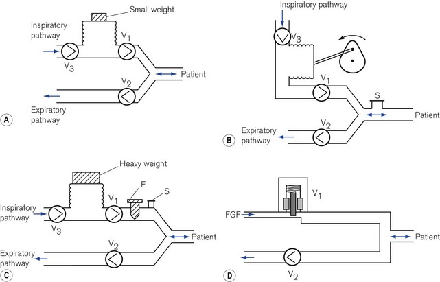
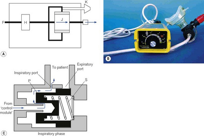
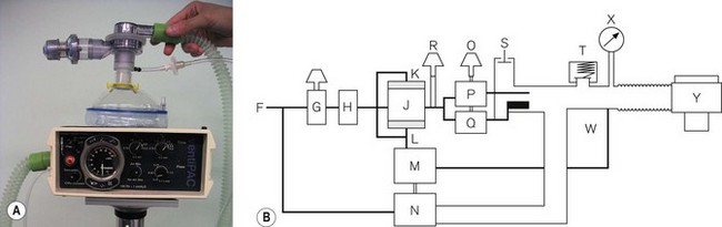
Respirable gas with sufficient pressure to ventilate a patient’s lungs may be supplied by a ventilator that obtains gas at atmospheric pressure and compresses and stores this in a bellows or bag by mechanical means (Fig. 9.1A, B and C). Alternatively, a ventilator can be designed to utilize a compressed gas from a cylinder or pipeline supply (Fig. 9.1D) and reduce this to suitable respirable pressures without the requirement of a storage bellows.
Classification of ventilators
Power
Low-powered ventilators
With the advent of modern electronics, many ventilators that fit this classification exclusively have become obsolete in the developed world. Some older ventilators and some of those designed for the developing world are so constructed that they can only deliver modest pressures (by using weak springs or light weights to compress the respirable gas in a bellows (Fig. 9.1A)). Such machines are simple to operate, reduce the potential incidence of barotrauma to lungs and, more pertinently, do not require an electrical power supply and are essentially user serviceable.
However, many current electronic high-powered ventilators have a pressure-controlled mode that allows operative characteristics similar to low-powered ventilators. When used in this mode and the inspiratory pressure is limited to 15–25 cm H2O via the machine’s electronics, the ventilator may be considered as low powered.
High-powered ventilators
In order to prevent a reduction in ventilator performance in the presence of deteriorating lung conditions, a ventilator needs to be powerful enough to overcome the increases in airways resistance and reduction in compliance with little alteration in desired gas flow. These ventilators require also the addition of certain safety features to protect patients with both normal and abnormal lungs from excessive pressures. For example, an overpressure safety valve is always included in the gas pathway to the patient to release any build-up of potentially dangerous pressures that might damage the lungs. Fig. 9.1B shows an example of a typical high-powered ventilator. The pressure-relief valve (S) can either be pre-set (usually at 4.4 kPa/45 cm H2O) or, in more sophisticated machines, can be adjustable (up to 7.8 kPa/80 cm H2O) to cope with severe conditions such as asthma and the adult respiratory distress syndrome. Higher-pressure relief settings, however, equate to increased risk of barotrauma.
Those high-powered ventilators that always generate high pressure of gas in the ventilator system prior to its delivery (by using powerful springs, heavy weights or a pipeline gas source (Fig. 9.1C and D) ), require the presence of a further safety device, a flow restrictor (see below), in the inspiratory pathway. This reduces the flow to the patient and prevents too rapid a build-up of pressure in the lung.
Alternative classifications
A popular classification with British anaesthetists has been described by Mushin.1 Those ventilators that by their design produce a pressure sufficient only to ventilate normal or mildly abnormal lungs are classified as pressure generators, i.e. the tidal volume delivered to the patient is limited by the pressures generated. Those ventilators that develop pressures sufficiently high enough to deliver a desired flow even to grossly abnormal lungs are deemed flow generators. However, as most other electromechanical devices in common usage are described in terms of power, the author prefers the first classification.
lnspiratory characteristics of ventilators
Low-powered ventilators
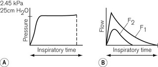
Low-powered ventilators deliver gas at modest pressure. This pressure is normally constant (Fig. 9.2A) and will produce an inspiratory flow rate of gas that is greatest in early inspiration, when the pressure differential between the ventilator and the lung is wide, but that slows during inflation of the lung as the pressures approximate (Fig. 9.2B).
High-powered ventilators
Inspiratory characteristics will depend on a number of factors. The high driving pressure from a pipeline source or heavy weighted/spring-loaded storage bellows requires some form of flow restriction to prevent too rapid a rise or an excessive pressure transmitted to the patient’s lungs that could produce barotrauma. This may take the form of a fixed orifice restrictor. Here the flow will be constant (pipeline supply or weighted bellows) or gradually decreasing (spring loaded bellows) as the tension in the spring reduces with emptying of the bellows (Fig. 9.3A). However, practically in the case of the latter the reduction is insignificant and flow is virtually constant.
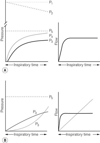
In more sophisticated ventilators, the inspiratory flow valve acts as a variable flow restrictor (Fig. 9.3B). These are able to respond to user-programmed inspiratory flow patterns.
Ventilators may be designed to force their bellows to be compressed either mechanically, via a linkage from a suitable power source, or pneumatically, by placing the bellows in a gas-tight container into which a pressurized gas source is fed (bag-in-bottle arrangement). The bellows in this type of ventilator normally fills with gas at near atmospheric pressures, so that when it is compressed, the pressure developed rises as it overcomes the resistive properties of the lungs. The resultant pressure and flow waveforms are dependent on the type of mechanical linkage (e.g. rotating cam/linear motor) or the type of pneumatic drive producing any of the waveforms seen in Fig. 9.3. Although these ventilators are classified as high powered, they do not require flow restrictors as there is no initial very high-pressure source present. However, they do need overpressure relief valves to protect against high pressures that might develop unexpectedly.
Classification of ventilators according to cycling
Expiratory cycling
• an expiratory volume-cycled ventilator may have a mechanism for terminating the expiratory phase when the reservoir bellows has filled to the desired tidal volume required for the next inspiration
• an expiratory pressure-cycled ventilator would be able to identify a selected airways pressure at the end of exhalation that would trigger the next inspiratory phase
• an expiratory flow-cycled ventilator would switch to the inspiratory phase when the desired flow rate at the end of exhalation was reached, or
• an expiratory time-cycled ventilator that terminates the expiratory phase after a predetermined time. This is the most versatile type as its phase may extend beyond the end of patient exhalation, unlike the others. It is, therefore, the most popular method of expiratory cycling and is achieved by using electronic or pneumatic timers within the ventilator to switch phases.
Further explanations are included in the individual ventilators mentioned below.
Cycling mechanisms in ventilators
Examples of these will be described where appropriate in the section on individual ventilators.
Ventilation modes
As ventilation strategies developed to include the ability to synchronize delivered tidal volume with the patient’s respiratory effort, the term synchronized intermittent mandatory ventilation (SIMV) became ubiquitous. A variety of approaches – many fundamentally similar – exist to the delivery of this type of ventilation by the different manufacturers, each, unfortunately, tending to use their own proprietary nomenclature (see Chapter 10).
In addition, a sophisticated ventilator may have a facility that supports spontaneous respiration by sensing an inspiratory breath and assisting it by adding extra gas from the device. This may be termed assisted spontaneous breathing (ASB) or pressure support ventilation (PSV). This may also be used in conjunction with SIMV. There are a number of other strategies used by manufacturers, which are explained in more detail in Chapter 10.
Ventilator controls (general principles)

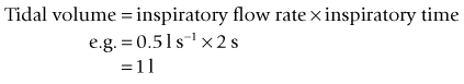

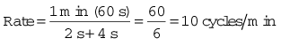
For example, if the inspiratory time is 2 s and the expiratory time is 4 s then:
Classification of ventilators according to application
Mechanical thumbs
The most common source of pressurized gas is that found in cylinders and pipelines. This may be administered to a patient most easily as a continuous flow into the simplest of breathing systems, the T-piece (Fig. 9.4A). In Fig. 9.4B, the anaesthetist has occluded the open end of the T-piece with his thumb. The force of the fresh gas flow (FGF) inflates the patient’s lungs until the anaesthetist removes his thumb from the open end, which allows expiration to occur (Fig. 9.4C). By rhythmical application of the thumb to occlude the T-piece, intermittent positive pressure ventilation (IPPV) is achieved. The FGF has to be high enough to inflate the lungs during inspiration and, as it is not stored during exhalation, this method is wasteful of gas. Therefore, it is suitable only for use in neonatal anaesthesia. Furthermore, the advent of more efficient ventilators and gas monitoring has seen the usage of this type of ventilation decline.
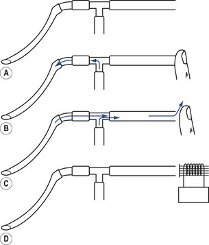
In ventilators such as the Sechrist (Fig. 9.5D), the anaesthetist’s thumb is replaced by a pneumatically operated valve (Fig. 9.5E), the cycling of which is determined by the settings on the ventilator controls.
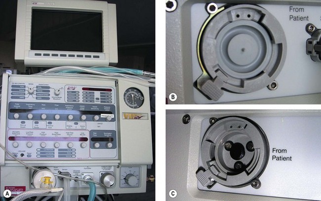
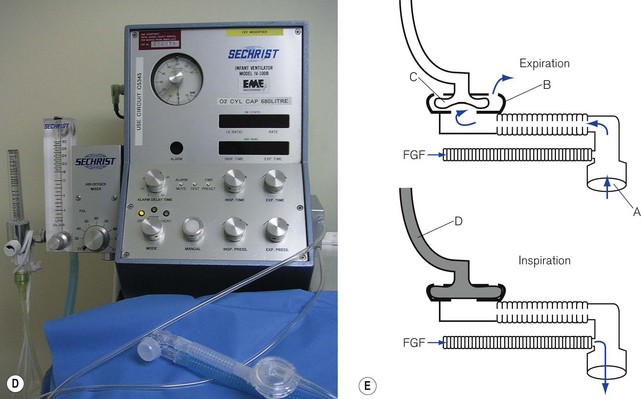
Figure 9.5 A. Bird VIP neonatal ventilator; B. Silicone diaphragm of Bird VIP acting as a variable flow valve; C. Bird VIP Piston from flow valve that moves the diaphragm. D. Seechrist infant ventilator; E. schematic diagram of the ‘mechanical thumb’. A, patient connection; B, expiratory valve; C, deflated pneumatic valve; D, gas supply tube to pneumatic valve, which is now inflated.
The exhalation valve may be electronically controlled (see Solenoids and Variable flow control valves, below) and by varying the degree of occlusion of the FGF is able to produce different types of inspiratory waveform (Bird VIP, Figs 9.5A, B and C). Some designs use gas jets in the opposite direction to the fresh gas in place of the valve for this purpose (SLE 2000).
Minute volume dividers
A more economical method of using a continuous source of pressurized gas is to feed it into a ventilator system (Fig. 9.6) to be collected by a reservoir R, which is continually pressurized by a spring, a weight or its own elastic recoil. Two valves, V1 and V2, are linked together and operated by a bi-stable mechanism. When V1 opens, V2 closes and causes the reservoir to discharge gas to the patient, i.e. this is the inspiratory phase. When V1 closes, V2 opens and expiration is permitted, allowing the reservoir bag to refill in preparation for the next breath.
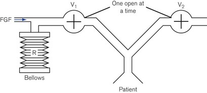
Servo 900 Series ventilator
The Servo 900 Series ventilator is a sophisticated multi-mode ventilator (see Chapter 10, Figs 10.19A and B). Many of its functions are more relevant to an intensive care environment; however, when used to ventilate anaesthetized patients it is most frequently used as a pneumatically driven, electronically controlled minute volume divider.
Bag squeezers
The driving gas from the ventilator does not ventilate the patient directly. The bellows (or bag) is squeezed pneumatically by enclosing it in a gas-tight Perspex canister and feeding the driving gas (under pressure) into the space between the bellows and canister (Figs 9.7A and B). The enclosed bellows is often referred to as a ‘bag in bottle’, which, although somewhat archaic (the original designs were just this), is perfectly descriptive. Fig. 9.7A shows a rising bellows arrangement. The bellows is filled by patient gas when in use and attached to a breathing system. For the rising bellows, the claimed advantage is that should it develop a leak, the bellows would collapse without any mixing of patient and drive gas. Its detractors claim that the pressure required to fill the bellows adds expiratory resistance and may prevent complete exhalation. Proponents claim that it provides a degree of positive end expiratory pressure (PEEP), which may be beneficial. The arrangement is very popular with many manufacturers of anaesthetic workstations (see below and Chapter 4).
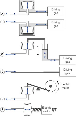
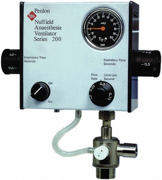
Fig. 9.7B shows a descending bellows arrangement. The patient gas is sucked into the bellows by a weight placed in the base. The alleged advantage is the absence of expiratory resistance. This arrangement also allowed the drive unit to be placed above the bellows in the free-standing versions. It could be placed on the lower shelf of an anaesthetic machine with the controls easily to hand. However, a tear in the wall would not result in a bellows collapse and driving gas would be able to enter the bellows and dilute patient gas. Also, the bellows is normally full of air prior to connection to a breathing system and needs to be purged prior to use. This design is no longer popular. The Penlon Nuffield 400 series ventilator was the most common example used in the UK, but is no longer produced (see previous editions).
The bellows may be both mechanically inflated and deflated by a lever attached to a gas-powered piston (Fig. 9.7C). This removes any potential risk of drive and patient gasses mixing. The piston may be driven by a smaller quantity of gas than in the methods described above. This could be important in situations where cylinders only are available. As the expiratory phase is controlled by the travel of the piston a second reservoir is required should exhalation be faster or slower than the ventilator so as to avoid respiratory embarrassment. This method is no longer popular with manufacturers. The most common models distributed in the UK were the Manley Servovent and the Oxford Mark 2 ventilators (see previous editions).
The bellows may also be squeezed mechanically, by means of a motor and suitable gears and levers. Fig. 9.7E shows a cam and piston arrangement. The movement of the cam produces a sinusoidal inspiratory pressure rise. In the expiratory phase the bellows may be re-expanded by the pull of the piston or if the piston rod is decoupled during this phase (‘lost motion drive’) by springs. This is no longer a common method.
Fig. 9.7F shows a bellows whose travel is produced by the linear travel of a worm gear driven by an electric motor. The speed of the motor can be altered both in inspiration and in exhalation to produce a variety of flows. This is the method used in the Dräger E series of ventilators (see later).
The bellows may be removed and a suitable length of wide-bore breathing hose substituted (Fig. 9.7D). In this arrangement, the ventilator may push the driving gas directly into the breathing system. This gas and patient gas are not physically separated, but the length of hose ensures that the driving gas does not enter the patient part of the breathing system (see Chapter 5). The Penlon Nuffield 200 series has probably been the most popular ventilator in the UK that uses this method.
Advances in ventilator designs
Electronic flow valves
There are three types of valve in common use.
Proportional (flow) valves (Fig. 9.8A) When an electric current is fed around a wire coil (solenoid) E in the valve, the magnetic field produced displaces a ferromagnetic core D that acts as a piston and opens a small valve C normally held shut by a spring F. The aperture exposed can be varied depending on the size of the current used, hence the correct term ‘proportional flow valve’. This type of valve is used in high-pressure gas pathways. The valve aperture is very small (1.5 mm2) and the movement of the valve is also small so that: (a) the flow can be rapidly varied between 1 and 120 L min−1 and (b) the size of the solenoid may be compact enough to fit into the equipment. The response time is usually less than 100 ms.
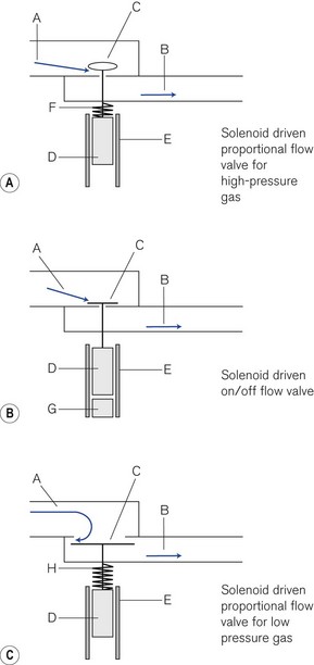
On/off valves (Fig. 9.8B) These are constructed in a similar fashion to a proportional flow valve. However, they function only as on/off valves. They may be used to switch a flow on or off. However, they can be pulsed on and off rapidly to produce a desired flow. Similarly, they may be used in parallel to blend gasses to a desired concentration. The valve is held shut by a magnet that attracts the ferromagnetic core inside the solenoid. When a steady current is fed around the solenoid, the magnetic field induced in the core opposes the fixed magnet and the valve opens. When the current flow ceases the magnet attracts the core and the valve shuts usually with the help of the incoming gas flow.
Low-pressure proportional flow valves This type of valve (Fig. 9.8C) (also Fig. 4.30) is held open by a delicate spring H. The valve and valve aperture are large to allow a high gas flow at low pressure. When the solenoid is activated, the valve (C) may be partially or completely closed. These devices are used mainly in low-pressure gas pathways as expiratory and PEEP valves.
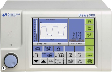
Spacelabs Healthcare (Blease) 700/900 series
This ventilator (Fig. 9.9A) is an electrolically controlled, pneumatically driven ‘bag squeezer’ with an ascending bellows arrangement. The driving gas is controlled by a rapid response proportional flow valve (Fig. 4.28) via a microprocessor to provide a wide range of ventilatory parameters. A line diagram of the pneumatics is shown in Fig. 9.9B.
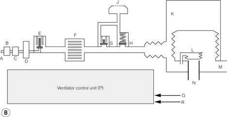
Expiratory phase At the end of the inspiratory phase, the expiratory valve G opens and the canister gas is vented to atmosphere (usually through the scavenging system on the workstation). The expiratory valve is a low-pressure proportional flow type (see above) with a light weight metal disc covering the expiratory port (Fig. 4.30). It is held in the closed position by a weak spring and a push rod connected to a solenoid arrangement. During normal exhalation, the pushrod is retracted by the solenoid to allow relatively unhindered expiratory flow. If PEEP is required the solenoid advances the pushrod so that it partially closes the valve to maintain the desired pressure.
Additional modes
The ventilator also supports most of the combination ventilatory modes, such as pressure-controlled SIMV (SIMV-PC), volume-controlled SIMV (SIMV-VC) and either of these with pressure-supported spontaneous breathing, e.g. SIMV-PC+PSV. An inspiratory pause can be dialled in, and there is the return of the ‘sigh’ option. The latter in default mode delivers a breath larger than tidal volume by 10% every 10th breath, although both values may be altered by the user. The ventilator may be used to ventilate paediatric patients using the appropriate flow sensor and ventilator settings.
Ventilator controls The front of the ventilator casing houses a flat panel TFT touch screen, similar to that found on a modern computer (Fig. 9.9A). Also, there is a rotary knob (Trak wheel) on the bottom left of this. Adjustable parameters may be selected by touching the appropriate box and using the up/down arrows to select the desired value. Alternatively the Trak wheel may be rotated to select a parameter. When pushed inwards (clicking) it highlights that value which may then be changed by further rotation. This value is confirmed by again ‘clicking’ on the wheel.
GE Healthcare 7900 Smartvent
This is another example of a pneumatically driven microprocessor controlled bag squeezer (Fig. 9.10). The operating principles are similar (although with minor variations) to that described above in that high-pressure driving gas is passed through an electronically controlled proportional flow valve to externally manipulate a bellows arrangement that contains patient gas. In this device the same proportional valve is used to deliver a bias flow to produce PEEP during the expiratory phase by acting on the passive expiratory valve (Fig. 9.10 B). The electronic control is handled by a programmable microprocessor to deliver a wide selection of respiratory modes. As with most anaesthetic ventilators of this type, these modes are similar to those found on a typical ITU device. Hence, there is VCV and PCV, both with SIMV facility and the ability to allow and/or pressure support a spontaneous breath. The GE version of pressure support ventilation (PSV Pro) may also be used to augment intended spontaneous respiration. This mode also has a back-up for unexpected apnoea. If the patient does not take a breath within the pre-set apnoea delay time, the apnoea alarm will activate and the ventilator will automatically switch to the back-up mode, which is SIMV-PC.
With the advent of fast response proportional valves, all these modes may be used in paediatric as well as adult patients. Different manufacturers often add subtle changes to various modes and also use slightly differing nomenclature for similar modes to that of their competitors. For example, the 7900 has a ‘volume guarantee’ mode in PCV. Here, the clinician sets an intended tidal volume, half of which is delivered in the first breath using volume controlled mode. The pressure generated by this breath is then used to calculate the level of pressure control for subsequent breaths which are gradually stepped up with the aim of achieving the set tidal volume within seven breaths. Hence all breaths after the first are delivered using pressure control to quickly reach the inspiratory pressure needed to achieve that the desired tidal volume at the set breath rate and I:E ratio. This information is constantly updated to ‘guarantee’ the desired tidal volume hence the mode being called PCV-VG.
Control panel (Fig. 9.10) This is housed in a flat panel display surrounded by various keys and a single rotary control that the manufacturer calls a command or ‘comm’ wheel. The display is divided into sections. The lower part of the screen has boxes with displayed values for intended tidal volume, rate, inspiratory/expiratory ratio, maximum pressure limit and PEEP. Below each of these is a ‘soft key’, which, when pressed, highlights that parameter. The latter may be adjusted to a new value by turning the comm wheel. The upper section of the display shows the measured ventilatory parameters and a graph of airways pressure. This information is retrieved from the twin flow transducers placed in the circle breathing system.
The bellows unit This unit houses the manufacturer’s circle absorber, a conventional rising bellows arrangement, inspiratory and expiratory flow transducers and an APL valve. The latter has a mandatory overpressure relief valve incorporated for safety during spontaneous breathing (see Chapter 4).
Dräger anaesthetic ventilators (E models)
The bag squeezer ventilators fitted currently to some of the anaesthetic workstations marketed by Dräger (Primus, Fabius and Cicero) are electrically powered and controlled (see also Chapter 4). These ventilators are made up from three modules, a control module, the ventilator module and the circle breathing system.
Control module (Fig. 9.11A) The ventilatory parameters available depend on the configuration of the control module in the model used. The basic model, the Fabius CE allows volume-controlled ventilation only. The top of the range Primus has the facility for both VCV and PCV, either as stand-alone features or with the provision for spontaneous breathing with and without pressure support in these modes. It also allows a purely spontaneous respiration mode with triggered pressure support. The control unit shown is a mid-range model, the Fabius GS. Like the ventilator described above, it has a rotary control (bottom right) to alter selected variables. On the left of the unit are the keys that select the mode of ventilation. The middle of the unit has a thin film transistor (TFT) screen that displays all the relevant information. To the right of this are two banks of keys to select the alarms, menu set-up, home, alarm silence and standby. The home key restores the screen to the default after any submenu called up is no longer required and the standby key stops the ventilator and keeps any ventilatory parameters selected for use again.
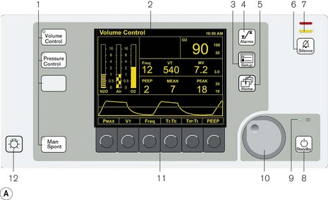
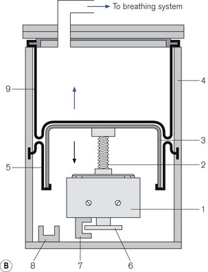
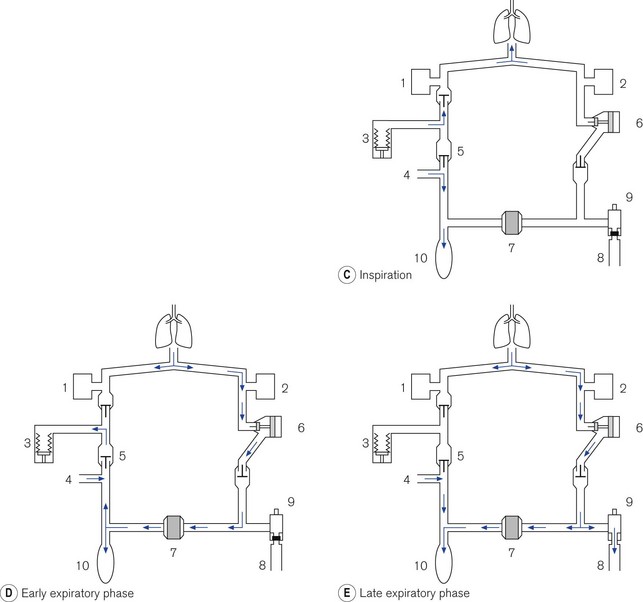
Figure 9.11 A. Dräger E ventilator as fitted to the Fabius GS: (1) ventilation mode hard keys; (2) user interface display screen; (3) set up key; (4) alarm limits hard key; (5) home key; (6) alarm silence key; (7) alarm status indicators; (8) standby mode key; (9) power on indicator; (10) rotary knob; (11) soft keys (functions); (12) lamp switch. B. Working principles: (1) electric motor; (2) rod with screw thread; (3) piston; (4) cylinder; (5) rolling rubber seal; (6) incremental encoder; (7) sensor; (8) light barrier; (9) ventilator bellows. C. inspiratory phase: (1) inspiratory flow transducer; (2) expiratory flow transducer; (3) ventilator; (4) fresh gas; (5) fresh gas decoupling; (6) valve controlling Pmax/PEEP; (7) absorber; (8) scavenging; (9) APL valve; (10) reservoir bag. D. early expiratory phase. E. late expiratory phase.
(Fig. 9.11A reproduced with permission from Dräger Medical UK.)
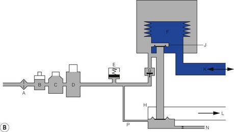
Ventilator module (Fig. 9.11B) Unlike the ventilators described above, this device does not require a pressurized source of gas as its power source. The ventilator has an electric motor (1) with a hollow spindle. The inside of the spindle has a screw thread. A rod (2) with a matching thread passes through the spindle. When the electric motor spins, the spindle rotates and the action of the two threads, which are interlocked, causes the rod to move through the spindle. This movement is referred to as either a recirculating ball screw or a worm drive. One end of the rod is connected to a piston (3) that moves backwards and forwards inside a cylinder (4), depending upon the direction and duration of current flow in the electric motor. The head of the piston is fitted with a rolling neoprene seal (5) so that on the downstroke it is capable of producing a sub-atmospheric pressure to the bellows that sits above it. The position of the piston rod at any one time is sensed by a high-resolution incremental encoder (6) and allows precise volume (0.03 ml) delivery. The encoder consists of a metal disc that has 1024 perforations around the edge. When the electric motor is working, this disc spins between two arms of a sensor (7) that counts the passage of the perforations and then calculates the linear movement of the piston rod. At the bottom of the cylinder there is a light barrier to detect the lower stop position of the piston.
• Inspiration (Fig. 9.11C). During the inspiratory phase the ventilator delivers the intended amount of volume to the patient. It does this by diverting the FGF from the anaesthetic machine via a decoupling valve (5) into the reservoir bag and not the patient. Furthermore, the delivered tidal volume from the ventilator enters the breathing system downstream of the absorber (which is isolated) and, therefore, minimizes the compression volume of the inspiratory pathway. The reservoir bag will be seen to expand with the addition of fresh gas, which may be a little unnerving for those not familiar with this system. There is a flow transducer in the inspiratory pathway that measures gas flow, which is then displayed on the control unit.
• Exhalation (Fig. 9.11D). The expiratory travel of the piston is fixed by the I/E ratio of the ventilator. The sub-atmospheric pressure created by the downstroke of the ventilator sucks in gas from both the reservoir bag and the exhalation volume from the patient. Towards the end of the exhalation phase, the reservoir bag fills and surplus gas is dumped through the scavenging port. Again the reservoir bag will be seen to move. In the top of the range machine, information from the expiratory flow transducer is passed to the microprocessor, which in turn causes the movement of the piston backstroke in the ventilator to match the expiratory flow.
Intermittent blowers
Pneumatic oscillator A typical example is seen in Fig. 9.12. The diagram is a very simplified version and does not attempt to show the detailed pneumatics that are essential for its function. Driving gas enters at point (1). It divides into three pathways. The main one passes to a cylinder that contains a shuttle (2), which travels between the ends of the cylinder. In the inspiratory phase (Fig. 9.12A), the driving gas passes into the cylinder and through a hole in the shuttle into the gas pathway (3) to the patient. The other two pathways supply two pneumatic timers (6) (inspiratory) and (7) (expiratory), each of which has a needle valve that regulates flow to the timer mechanism at the relevant end of the cylinder. When the flow causes sufficient build up of pressure in the inspiratory timer, the shuttle is forced to the opposite end of the cylinder (Fig. 9.12B) and in doing so causes three events:
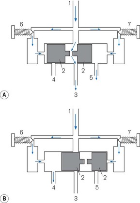
1. It blocks off the flow of driving gas through the cylinder terminating the inspiratory flow.
2. It opens a vent (4) to open on the inspiratory side of the cylinder that allows the pressure in the inspiratory timer to be released.
3. It causes the shuttle to occlude the expiratory timer vent (5) so that a pressure can build up to reverse the direction of the shuttle and terminate the expiratory phase.
Working principles of pneumatically controlled intermittent blowers
A generic line diagram of a typical pneumatically powered and controlled ‘intermittent blower’ is shown in Fig. 9.13. High-pressure driving gas (300–400 kPa) is connected to the device at point (F). When the main pneumatics on/off switch (G) is turned on, gas flows through it to a regulator (H) that reduces the driving pressure to approximately 275 kPa. Gas flows on to the oscillator (J). The output from this passes through a variable flow restrictor and exits the device to be attached to a breathing system. The delivered tidal volume is a function of the inspiratory timer (K), which is calibrated in seconds, and flow restrictor (R), which is calibrated in l s−1. The respiratory rate is determined by the cycle time: inspiratory time (adjusted at K) plus the expiratory time (adjusted at L).
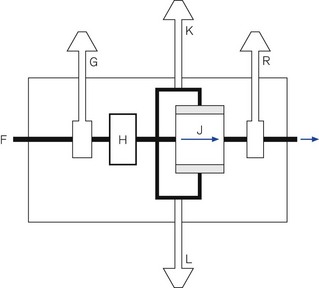
Classification of intermittent blowers
Intermittent blowers are used in four different ways (Fig. 9.14).
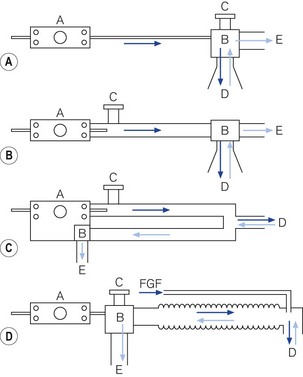
Figure 9.14 Classification of intermittent blowers. A. Basic resuscitator. B. Sophisticated resuscitator. C. Ventilator for intensive care. D. Anaesthetic ventilator for Mapleson D system. A, resuscitator/ventilator; B, patient valve; C, overpressure relief valve; D, patient pathway; E, expiratory pathway.
Basic resuscitators
The simplest design is used as a basic resuscitator (Fig. 9.14A). The working principles are shown in Fig. 9.15A. It has no separate on/off switch and no flow restrictor and a fixed expiratory timer. It has a single control (K) for tidal volume, cycling rate and I/E ratio, which is actually the variable inspiratory timer. Since the flow rate is constant, when the inspiratory time is lengthened, the tidal volume is increased, the cycling rate is reduced and the I/E ratio is prolonged, and vice versa.
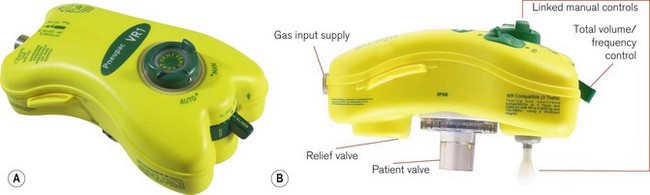
An example of this type is the Pneupac adult/child resuscitator (Fig. 9.15B), which, although no longer in production (since 2004), is still widely used.
The working principles of the patient valve are explained in Fig. 9.15C.
Sophisticated resuscitators
This basic model has been superseded by the Pneupac VR1 (Fig. 9.16), which now has an on/off switch, manual mode to comply with International Liaison Committee on Resuscitation (ILCOR) CPR guidelines, a demand function to allow spontaneous breathing through the device and variable flows across the frequency range to deliver gentler breaths. These devices can also be used in toxic environments (for example hazardous area response teams: HART). The working principle is very much as in Fig. 9.17A (see below), but with controls K, L and R combined in one single control for the user. This allows greater speed in the deployment of the device. The variable flows are also available when pushing the manual control button. The manual control is now a standard feature on most resuscitators to allow compliance with the changing CPR ventilation to chest compression ratios (currently 2/30). Also most basic resuscitators now allow direct connection of the patient valve to the resuscitator so that it can be used on top of the mask/tracheal tube (Fig. 9.16B). Alternatively, a length of wide bore tubing may be placed between the patient valve and resuscitator (see Fig. 9.17A).
More features may be added to a resuscitator to increase its scope. However, it then starts to resemble an ITU ventilator. An example is the Pneupac Ventipac (Fig. 9.17A). The increased sophistication may be seen in the line diagram Fig. 9.17B. The output from the oscillator (J) is passed via a variable flow restrictor (R) on to two coupled needle valves (P) and (Q), operated by a switch (O). If P (air mix mode) is selected, the driving gas is passed into a Venturi that entrains a fixed amount of ambient air from S (this port has a non-return valve) and the total flow is fed into the patient breathing system.
Intensive care ventilators
Fig. 9.14C shows a very basic line diagram of an intermittent blower used as typical intensive care ventilator. These are discussed in more detail in Chapter 10.
Ventilators for anaesthetic breathing systems
Fig. 9.14D illustrates the use of an intermittent blower with an anaesthetic breathing system. The patient valve may be placed adjacent to the ventilator and the output connected to a breathing system (Mapleson D or circle system) in place of the normal reservoir bag (see Chapter 5). It must be remembered that sufficient length of wide-bore hosing must be used between the ventilator and the breathing system to prevent any driving gas from diluting the anaesthetic intended for the patient. The ventilator that popularized this method in the UK is the Penlon Nuffield 200 series (Fig. 9.18).
Jet ventilation
There are two ways in which a high-pressure jet of gas may be used to ventilate a patient.
Manually controlled jetting
For short procedures such as rigid bronchoscopy, a patient may be anaesthetized and then ventilated by applying an intermittent jet via the bronchoscope, using a manually operated injector device such as the Manujet (see Airway management devices, Chapter 6). The jet behaves as a Venturi causing air to be entrained by the driving gas. The latter is usually oxygen, at a pressure of up of 420 kPa (60 psi). Anaesthesia is normally maintained intravenously.
Automatically controlled jetting
The Acutronic ‘Monsoon’ jet ventilator is one example of this in Europe and the UK. The Monsoon has a built-in humidifier system for use in longer procedures and the intensive care unit. It is based around high-performance, electronically controlled solenoid flow valves. The basic model has a single valve capable of frequencies from 12 to 1600 cycles per minute. The Monsoon + (Fig. 9.19) has a second valve capable of 1–100 cyclesl min−1 to allow either stand-alone ventilation or the superimposition of a second low-frequency, tidal-type ventilation. The ventilator has three main controls. One alters the rate, another controls the I/E ratio (by altering the percentage of the cycle that is inspiration), and the third operates a reducing valve that controls the output pressure of the driving gas. (In the advanced model, there are duplicate controls for the second jet.) The delivered tidal volume/minute volume depends on a combination of all three settings and all of these ventilatory parameters are displayed on a screen on the front panel of the device.
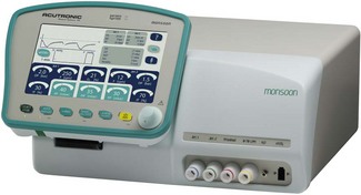
The Monsoon measures the ‘airways’ pressures proximally and distally throughout the respiratory cycle and displays them on the user panel. Peak inspiratory pressure (PIP), mean airway pressure (MAP) and end expiratory pressure (EEP) are measured directly from the patient’s airway: typically from a second lumen of the jetting catheter. Alarm conditions for these variables will prevent delivery of subsequent breaths until the alarm condition is rectified. The pause pressure (PP) measures the pressure decay in the jet connection tube itself (at its origin in the machine) during the expiratory phase. If this has not dropped below a pre-set limit within 10 ms of the next jet, the ventilator stops that jet cycle. This safety feature is designed to reduce the risk of barotrauma from ‘breath stacking’ (due to an obstructed patient anatomical airway preventing exhalation), even when a single lumen catheter with no facility for tracheal pressure measurement is used for jet ventilation (e.g. a Ravussin Cannula, see Chapter 8). It is important to note that as the expiratory time shortens at high jetting rates, due to the delay in the decay of the pressure waveform, the measured PP reflects less and less the pressure at the distal end of the jetting device (i.e the EEP). An integral part of the ventilator is therefore the test lung that is supplied with the device, allowing the machine to be set with appropriate parameters before connecting to the patient.
Features of jet ventilation
Frequency
• Gas exchange occurs by normal tidal ventilation, hence.
• Normal tidal volumes are required for carbon dioxide elimination.
• The ventilation can be carried with a manual injector.
• There is sufficient time during exhalation for conventional methods to be used in the measurement of carbon dioxide elimination.
• Larger movements of gas in and out of the laryngeal inlet may cause sufficient movement of the vocal cords to preclude any operative procedure.
• Inflation pressures can be high, if a manual injector is used without meticulous attention to adequate exhalation, and may easily embarrass cardiac output or cause barotrauma.
• more efficient alveolar ventilation with much lower tidal volumes
• a substantial reduction in mean airway and alveolar pressures with a reduced potential for barotrauma
• a minimal disturbance of cardiac output, and subsequent renal function
• a reduction in leaks from broncho-pleural fistulae, often with an improvement in gas exchange
• a more comfortable method of providing ventilatory support for patients in the intensive care unit
• for surgical procedures the target site is more stable and only vibrates
• expensive and unfamiliar equipment is needed
• altering ventilatory parameters causes less intuitive changes in physiological variables.
Spacelabs IBlease 700/900 User Manual, March 2010.
GE Healthcare 7900 Smartvent™, Specification.pdf. 2005.
GE Healthcare Aisys brochure pdf 2006.
Penlon Nuffield 200 Technical description (200 4tecNV200.ppt), 2004.
Glaister C. Dräger Fabius GS Training notes. Dräger UK; February 2003.
Smiths Medical Pneupac®VR1 Emergency and Transport Ventilator smoths-medical.com/Pneupac
Sims Pneupac Principles of operation of ventiPAC Pneupac Ltd.2002 Part No504-2101 Issue 1 07/2003.
Acutronic Technical: Service Manual MONSOON III Software 5.0.