[level-membership-for-neurology-category]
Chapter 176 Atlantoaxial Instability and Stabilization
The atlantoaxial junction is a delicate anatomic complex that involves an intricate relationship between the atlas and the axis to allow flexion, extension, rotation, and lateral bending.1 The interrelation of osseous, ligamentous, neural elements, and articulations make the atlantoaxial junction vulnerable to instability and potentially devastating neurologic complications. A myriad of surgical treatment options exist, ranging from fixation with and without dorsal surgical fusion and/or internal fixation using screw techniques and/or wiring techniques. This chapter reviews the different atlantoaxial fixation techniques, including their indications, limitations, and complications.
Anatomic Considerations in Treating C1 and C2 Injuries
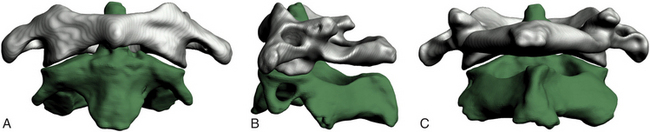
The atlas supports the globe of the head and has very unique anatomic characteristics that separate it from other vertebrae. It is essentially a bony ring without a body consisting of an anterior arch as well as two lateral masses connected to a posterior arch by two pedicles (Fig. 176-1). The longus colli muscles attach to the anterior arch via a small bony prominence, the anterior tubercle, which is a rudimentary vertebral body. The posterior aspect of the anterior arch has an indentation, the fovea dentis, to serve to accommodate the odontoid process of C2. The posterior arch joins together to form the posterior tubercle over the posterior midline. It is the attachment point for the posterior atlanto-occipital membrane and the rectus capitis posterior minor muscles. The upper aspect of the posterior arch contains the vertebral arteries within the sulcus arteriae vertebralis. The vertebral arteries travel within the sulcus medially before ascending to penetrate the dura. The lateral masses have large, concave superior surfaces to articulate with the occipital condyles. They are directed upward, medially, and backward and form a cup for the corresponding condyle. The inferior surfaces are circular and directed downward and medially to articulate with the superior articulating facet of C2 and form the zygapophyseal joints, which allows flexion-extension, side-bending, and rotational movements. The atlantoaxial joint is the articulation between C1 and C2 and has a range of motion in the transverse plane for rotation. This rotation is facilitated by the odontoid process, which acts as a pivot point for the rotation of C1. The transverse processes project farther laterally than the transverse processes on the adjacent cervical vertebrae. The apex of the transverse process can be felt through the skin between the mastoid process and the angle of the mandible.2 Several muscles attach to it. The superior obliques arise from the upper surface of the transverse process and extend to the occiput, and the levator scapulae, splenius cervicis, and the scalenus medius attach to the inferior and lateral surfaces of the transverse process. The inferior obliques extend from the inferior surface of the transverse processes to the spinous process of C2. The transverse processes also contain the transverse foramina. The atlantoaxial articulation is composed of three synovial joints: the paired lateral mass articulations and the central articulation between the dens and the anterior arch of C1 and the transverse ligament. The transverse ligament attaches just below the medial margin of each superior facet, stretching across the atlantal ring and dividing the vertebral foramen into an anterior part, which receives the dens, and a posterior part, which transmits the spinal cord. The transverse ligament is the major stabilizer at the C1-C2 level. The cruciform ligament consists of the superior and inferior longitudinal fasciculi, which extend to insert into the anterior foramen magnum and the posterior body of the axis, respectively. Other important ligaments include the anterior atlantoaxial ligament, which extends caudally to form the anterior longitudinal ligament in the subaxial spine; the posterior atlantoaxial ligament, which extends caudally to form the ligamentum flavum; the apical ligament, which connects the tip of the dens to the foramen magnum; and the alar ligaments, which extend from the lateral dens to attach to the occipital condyles.
Indications for Fixation
The indications for fixation are described in the following subsections.
Trauma
Because of the fragile nature of the bony and ligamentous components of the upper cervical spine, injuries to this region are common. The mechanisms of injury include flexion, extension, or compressive forces applied to the head during motor vehicle accidents, falls, or sports-related injuries. Trauma to the atlantoaxial complex can lead to significant instability and may require surgical fixation. Fractures of the dens are common injuries requiring fixation. In some cases, these fractures can be treated using an anterior approach, thus sparing motion; in other circumstances, a posterior approach may be indicated.
Odontoid Fractures
Classification
The most widely accepted classification for odontoid fractures is the Anderson and D’Alonzo classification, which is based on the fracture line.3 The criteria for the treatment algorithms for these types of fractures pertain to the fracture line, the amount of displacement, and a concurrent ligamentous injury. It is therefore imperative to perform computed tomography (CT) and MRI for evaluation. Type I is a stable avulsion fracture that involves the tip of the dens and, in general, leaves the ligamentous complex intact. Treatment involves the use of a cervical collar and symptomatic relief. However, it is imperative to evaluate the craniocervical junction with a flexion-extension dynamic study to rule out concomitant ligamentous injury and instability. Type II odontoid fractures are inherently unstable and occur at the junction of the C2 vertebral body and the dens. The treatment options and their union rate vary with the amount of displacement: With less than 6 mm displacement, external halo fixation carries a 93% union rate4; with 6 mm or more displacement or with comminuted fragments of the base of the dens (type IIa), the disunion rate is as high as 75% to 85% and internal fixation needs to be considered.4,5 Type II odontoid fractures can also lead to transverse ligament injury.6 The integrity of the transverse ligament is essential in making the decision to use anterior odontoid screw fixation. If the ligament is intact, one can proceed with odontoid screw fixation; otherwise, a C1-C2 fixation is necessary. The techniques for C1-C2 fusion and for anterior odontoid screw fixation are discussed below. Type III odontoid fractures extend into the cancellous portion of the C2 vertebral body. They are considered unstable fractures and are treated by reduction with skeletal traction as needed and immobilization with a collar or halo. Surgery is indicated if there is persistent disunion after 12 weeks of orthosis use.
Traumatic Spondylolisthesis of the Axis (Hangman’s Fracture)
Traumatic spondylolisthesis of the axis was first described in convicts who were hanged, hence its nickname, Hangman’s fracture. When the convict fell into the rope, the neck was distracted and hyperextended, resulting in rupture of the C2-C3 disc and fracture of C2. Hangman’s fractures account for approximately 7% of all cervical fractures. Today the most common cause of traumatic spondylolisthesis of the axis is a hyperextension-compression injury. This explains the fact that patients who sustain these fractures seldom have neurologic complications. Hangman’s fractures cross the pars interarticularis of C2 and are classified by Effendi et al7 into three types: Type I Hangman’s fractures account for 65% of all traumatic spondylolistheses and consist of a stable, nondislocated fracture with intact C2-C3 disc space, type II involves a ruptured C2-C3 disc with dislocation of the C2, and C2-C3 is unstable. It account for 28% of traumatic spondylolisthesis, and type III adds a unilateral C2-C3 dislocation to the type II definition.
Fractures of the Atlas
Atlas fractures account for approximately 2% to 13% of all cervical spinal injuries and are classified according to Gehweiler and colleagues8 as follows:
• Type I: isolated fracture of the anterior arch of C1
• Type II: isolated fracture of the posterior arch of C1
• Type III: combined anterior-posterior fracture (Jefferson fracture)
Type I fracture is a horizontal avulsion injury of the caudal portion of the anterior arch due to the contraction of the longus colli during hyperextension. Hence the circumferential integrity of the atlas is maintained, and treatment involves symptomatic relief and a collar. With concomitant dens dislocation, the fracture can become unstable, and the algorithm follows that of an odontoid fracture. In type II injuries, the fracture is located in the weakest part of the posterior arch, usually at the sulcus arteriae vertebralis, and it is bilateral. It is a hyperextension and axial loading injury that is usually not accompanied by neurologic deficit, since the osseous structures are pushed outward. A concomitant dens fracture needs to be excluded during the differential diagnosis and treatment is symptomatic. Type III injury, or Jefferson fracture, was first described by Jefferson in the 1920s.9,10 It involves both the anterior and the posterior arch of C1 and can include unilateral and/or bilateral fractures on either arch. Type III is an axial loading injury with lateral displacement of the fragments that can include a concurrent avulsion injury of the transverse ligament. The latter renders a Jefferson fracture unstable. It is therefore imperative to exclude injury of the transverse ligament on the basis of radiographic evidence of a Jefferson fracture. Spence’s rule assumes a rupture of the transverse ligament if the step-off of the lateral masses confirmed by a transoral open-mouth view or by coronal reconstructive CT is at least 7 mm. If the sum is less than 7 mm, a flexion-extension study can be obtained to rule out underlying instability. Types IV and V fractures are rare, stable fractures requiring symptomatic treatment. With transverse process fractures, there is a risk of thrombosis of the vertebral artery. Obtaining an arteriogram may become necessary if there are clinical signs of vertebral artery thrombosis. Patients with all of these injuries need to have follow-up flexion-extension examinations to rule out ligamentous laxity after the fractures have healed.
Isolated Transverse Ligament Injury
Traditionally, Spence’s rule is applied to identify a transverse ligament injury radiographically. More recently, some authors have indicated that MRI is a more sensitive indicator of transverse ligament injury than Spence’s rule.6,11,12 Dickman et al11 classified isolated transverse ligament injuries into two different types based on MRI: type I is an injury of the transverse ligament without concurrent atlantal fracture, and type II involves an avulsion fracture at the insertion of the ligament into the medial aspect of the arch. In their series of 39 patients with axial and atlantal fractures, they concluded that use of Spence’s rule would have missed 60% of transverse ligament injuries (as determined by MRI). They suggested that type I transverse ligament injuries need to be treated with early surgery and favor external halo immobilization for type II fractures.12
Ligamentous Injury
Flexion of the upper cervical spine can lead to ligamentous injuries and subsequent laxity without bony injury. A value greater or equal to 5 mm for the anterior atlantodental interval in adults (normal value, 2 to 4 mm in adults and 7 mm in adult patients with Down syndrome) indicates ligamentous laxity, and a value greater than 10 to 12 mm indicates complete ligamentous destruction.13 Axial rotation of the upper cervical spine is limited by the alar ligaments, and damage to these ligaments increases rotation on the contralateral side by 30%.14 Failure of any of the components of the atlantoaxial ligament complex requires dorsal surgical fusion.
Rheumatoid Arthritis
Rheumatoid arthritis (RA) is a systemic disease that can affect the atlantoaxial junction and subaxial vertebrae. Eighty-eight percent of RA patients have involvement of the C1-C2 junction.15 As many as half of patients with RA develop symptomatic atlantoaxial subluxation, 56% of whom have myelopathy.16 Postmortem examinations have indicated C1-C2 instability as the cause of death in as many as 10% of patients.17 Classic radiographic findings include the staircase phenomenon, which is due to multiple subluxations involving the atlantoaxial and subaxial joints. In general, the following are indications for surgical intervention: spinal cord compression, severe neck symptoms, and marked subluxation. Any combination of two of the following factors also warrants surgery: cervical myelopathy, delayed central motor latency, spinal cord diameter less than 6 mm in a neutral or flexed position observed on an MRI study or less than 10 mm upon flexion, pannus more than 10 mm behind the dens, and anterior atlantodental distance more than 10 mm. Some authors advocate surgical intervention if the posterior atlantodental interval is less than or equal to 14 mm, even without neurologic symptoms.18
Congenital Abnormalities
Any congenital abnormality that prevents optimal development of the osseous (dens) and/or ligamentous structures (cruciate ligament) can lead to atlantoaxial instability. Os odontoideum is a failure of the dens to fuse with the body of the axis and, together with odontoid agenesis, can lead to ligamentous laxity or underdevelopment and hence instability, requiring surgical intervention.19,20
OS Odontoideum
Os odontoideum is an ossicle with smooth circumferential cortical margins that represent the dens without osseous continuity with the body of C2.21,22 The etiology of this entity remains disputed (acquired vs. congenital), but the etiology is of no importance in the treatment algorithms.20 Os odontoideum can be classified as orthotopic and dystrophic. The former defines an ossicle that moves with the anterior arch of C1 and can sublux anterior to the arch,23 and the latter describes an ossicle that is fused to the basion. The natural history of os odontoideum is variable, and no predictive factors for a clinical scenario have been identified. Surgical treatment of os odontoideum correlates with the presence or absence of C1-C2 instability. Patients without neurologic deficits and without C1-C2 instability on flexion-extension can be managed conservatively. Although some patients with instability have been treated nonoperatively, most surgeons advocate operative stabilization and C1-C2 fusion. The concern is that with this constellation there is a higher risk of future spinal cord injury, and several studies have indicated that surgery has merit.24–27 Furthermore, longitudinal radiographic and clinical surveillance is recommended for all conservatively treated patients.23 Screw fixation techniques have the advantage that no postoperative external fixation is required. The last category of etiologies that can lead to instability of the atlantoaxial junction includes infectious and neoplastic processes affecting the C1-C2 junction.
Dorsal Wiring Techniques
Gallie Fusion
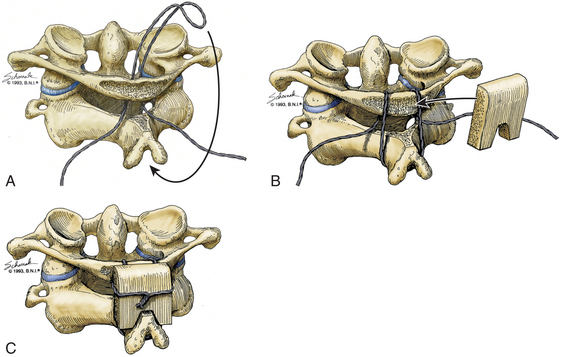
Initially described in 1939, the Gallie dorsal wiring fusion technique is a simple surgical fixation method (Fig. 176-2).28 It consists of placement of a medial bone graft between the posterior arch of C1 and the spinous process of C2, with sublaminar wiring around the arch of C1 and looping around the C2 spinous process. For the sublaminar placement of the wire, a 1.2-mm wire is looped into a hook configuration and passed from the inferior aspect of posterior arch of C1 ventrally to the arch of C1 and over the posterior aspect of the arch of C1. Attention should be paid so that no injury to the spinal cord occurs during that process. The loop is then pulled caudally enough to hook it over the spinous process of C2. The arch of C1 and the lamina of C2 are decorticated, and a bone graft in an H configuration is placed over the decorticated area and fixated with the two lateral ends of the wire. The area around the bone graft can then be packed with more cancellous bone. This technique is the simplest and poorest form of biomechanical stabilization. It requires an intact C1 arch, and as such it cannot be used to treat Jefferson fractures or any entities with involvement of the posterior arch of C1, such as infections, tumors, and rheumatoid arthritis. It offers minimal rotational stability and requires postoperative external immobilization.29 Its disunion rate is rather high at 25%, and this technique is most often used to supplement other stabilization methods.30
Brooks-Jenkins Fusion
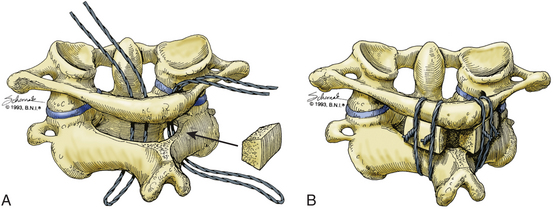
For the Brooks-Jenkins wiring technique,31 the laminae of C1 and C2 are dissected and two 20-gauge wires are passed under the lamina bilaterally (Fig. 176-3). Two bone grafts are then placed into the lateral interlaminar space on each side, held in place by the wires. As compared to the Gallie technique, this technique allows more rotational stability with higher fusion success rates of up to 93% with the use of a halo postoperatively. This technique has the same contraindication as the Gallie technique and requires an intact C1 posterior arch. In addition, the passage of two wires can result in wider curvature and a “clothesline” compression of the spinal cord.32
Sonntag’s Modified Gallie Fusion
Sonntag and colleagues33 introduced the modified Gallie dorsal wiring fusion technique to provide more stability than the classic Gallie technique. The intralaminar space between C1 and C2 is widened by using a high-speed drill, and a single bicortical graft is fitted into that space. The lamina and the spinous process of C2 are decorticated, and two 24-gauge sublaminar wires are passed around the posterior arch of C1, over the graft, and around the spinous process of the axis. Like the Gallie technique, the Sonntag technique requires an intact posterior arch. Another disadvantage of the Sonntag technique is the postoperative need for external fixation. The halo will be used for 3 months after surgery, and subsequently the patients need to be in a hard collar for 4 to 6 weeks.
Interlaminar Clamp Technique (Halifax Clamps)
The interlaminar clamp technique provides results similar to those achieved with the use of the Brooks-Jenkins technique,31 but without its disadvantages (Fig. 176-4). In this technique, with the use of Halifax clamps, a double-hook is placed bilaterally over the superior edge of the posterior arch of C1 and the inferior edge of the lamina of C2. Each hook secures small bone grafts over the decorticated laminae of C1 and C2.32 Initially described as a unilateral technique without any graft placement, the use of bilateral bone grafts has subsequently been shown to yield superior results.34 This technique provides excellent anteroposterior stability with less rotational stability compared to the Brooks-Jenkins technique31 and Magerl and Seemann’s technique (see “Magerl Transarticular Screw Technique” below).35 Similar to all other wiring techniques, it requires an intact posterior arch of C1. One advantage over the other wiring techniques is the fact that postoperative immobilization can be achieved with a collar and does not require halo placement. The clamps can fail with rotation and hyperextension if the graft is undersized or brittle, thus this technique has fallen out of favor today.
Screw Fixation Techniques
Magerl Transarticular Screw Technique
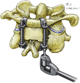
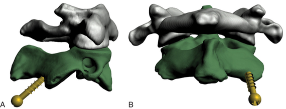
Magerl’s technique was first described in 1986 and later in 1992.35,36 It has two distinct advantages over dorsal wiring techniques: (1) the transarticular screw placement significantly increases rotational stability, and (2) it does not require a stable posterior arch and can therefore be used in cases where dorsal wiring is contraindicated (Fig. 176-5).
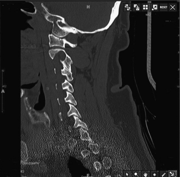
Preoperative planning with fine-cut CT of the C1-C2 junction is essential to determining a possible high-riding vertebral artery that would preclude C2 screw placement because of the risk of injury (Fig. 176-6).37 Cadaveric studies have demonstrated that bilateral screw placement may not be possible in up to 20% of specimens because of variations in the anatomy of the vertebral artery that preclude safe placement.38,39 Fiberoptic intubation and perioperative motor-evoked and somatosensory-evoked potential measurement are advocated by some surgeons, including the authors.40 After positioning the patient in a prone position, the surgeon can attempt a closed reduction under fluoroscopic guidance by traction with Gardner-Wells tongs or a halo or with a Mayfield clamp. (The latter allows better translational control.) The patient is positioned in a military flexion position to facilitate screw placement. Use of these maneuvers can result in a technically simpler operation.
A midline incision is made from the occiput to C3. Using a subperiosteal dissection technique, the laminae of C1, C2, and C3 are exposed. Care is taken not to expose the articular process of C2 and C3 such that the C2-C3 joint is not injured. After the laminae of C1 and C2 are exposed, attention is then turned toward the lateral aspect of the lamina of C2 and the lateral mass of C2. The isthmus of C2, where the lamina and lateral mass join, is identified. This is carefully exposed and followed rostrally until the C1-C2 joint is encountered. The C2 nerve root crossing posterior to the C1-C2 joint is gently elevated to provide further exposure. The articulation at C1-C2 is identified, and a Penfield 4 is used to remove the cartilage to promote bony fusion of the joint. Caution is required not to introduce the instrument too laterally and cause injury to the vertebral artery. The entry point for screw placement is then determined. It is usually 2 to 3 mm lateral and 2 to 3 mm rostral to the medial aspect of the C2-C3 facet. Using a 3-mm cutting burr, an entry point hole is made in this location. The angle for the drilling and screw placement may require a percutaneous approach at the level of C7. To this end, a stab incision is made over the lateral aspect of the spinous prominence of C7. A Kirschner wire is then drilled through the C2 lateral mass and across the C1-C2 articulation into the lateral mass of C1. The Kirschner wire is placed using live lateral fluoroscopy and aiming the wire toward the anterior tubercle of C1. A cannulated 2.5-mm AO drill is passed over the Kirschner wire. A tap is used for the entire length of the trajectory all the way to the anterior cortex of the atlas without breaching it. Up to 70% of screws have been reported to perforate the anterior cortex without any clinical consequence.41 However, an injury to the carotid artery is possible and has catastrophic consequences. A 3.5-mm screw is then inserted through the percutaneous stab incision and threaded under fluoroscopic guidance. The contralateral screw is placed using the same technique. Dorsal wiring techniques can then be used for reinforcement as described above.42 The laminae of C1 and C2 are decorticated, and bone graft is placed to promote bony fusion. If a laminectomy is required, grafting can be performed only at the C1-C2 articulation.
The stability of this technique in flexion, extension and rotation has been demonstrated in several instances including a high fusion rate as compared to various wiring techniques with halo (86% to 100%).37,39,40,43–45 Complications are rare with the use of fluoroscopy and systematic implementation of the technical steps. Injury to the vertebral artery has been well-documented and has been reported to be between 4% and 8%.38,41,46 Among those patients, fewer than 4% sustained any neurologic injury.47 Bilateral injury of the vertebral artery can be fatal, and, in general, if there is an injury to a vertebral artery, the screw should be placed to stop the bleeding and the placement of the contralateral screw is then aborted. Other complications include hardware failure (4%), malpositioned screws (14%), and temporary hypoglossal nerve paresis (2%).39 If the placement fails, conversion to a rod cantilever technique may be required with or without extension to C3.
C1-C2 Rod Cantilever Technique
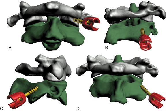
Magerl’s technique provides excellent stability and fusion rates, but it is technically demanding (Fig. 176-7). In addition, 1 in 25 patients cannot have a transarticular screw placed, owing to anatomic variation.38,39 To overcome this problem, the C1-C2 rod cantilever technique uses independent screw placement at C1 (lateral mass screws) and C2 (pedicle screws) together with rod placement.48–51
A Penfield 4 can be inserted into the C1-C2 joint to retract the C2 nerve root caudally and also to indicate the caudal-rostral trajectory for placement of the C1 lateral mass screw. Using a 3-mm diamond burr, an entry point is created at the base of the C1 pedicle at the midpoint of the C1 lateral mass. Using an AO drill, a bicortical hole is made through the C1 lateral mass. The caudal-rostral trajectory will be parallel to the Penfield 4. The lateral-medial trajectory will be 15° medially. Care must be taken when placing this hole bicortically, as the carotid artery and hypoglossal nerve pass ventral to C1 in this region. A 3.5-mm-diameter screw is then placed, and the Penfield is removed. The entry point for the C2 pedicle screw is 4 mm below the interface of the C2 isthmus and lateral mass and approximately 4 mm from the lateral aspect of the lateral mass. A 3-mm hole is placed at this entry point. The hole for the screw is made with a 3-mm fluted tap. The caudal-rostral trajectory is parallel to the surface of the C2 isthmus. The lateral-medial trajectory is determined by drawing an imaginary line that starts at the entry point and intersects the medial aspect of the C2 isthmus as it joins the C2 vertebral body. After the hole is made, a 3.5-mm-diameter screw is placed. Although some authors have advocated the use of intraoperative fluoroscopy, free-hand placement of pedicle screws in the axis has been described.52 Two rods are contoured to span the C1 and C2 screws. These are placed in position and locked to the screws with locking nuts. Dorsal wiring techniques can then be used for reinforcement as described above.42 The laminae of C1 and C2 are decorticated, and bone graft is placed to promote bony fusion. If a laminectomy is required, grafting can be performed only at the C1-C2 articulation. This technique has yielded excellent fusion rates, and no vertebral artery or spinal cord injuries have been reported.48,50 Nevertheless, a high-riding vertebral artery or a small C2 pars can preclude the use of this technique.53 In those cases, unilateral C2 pedicle screw placement is possible with extension of the construct to C3.
C2 Laminar Screw Placement––Wright’s Technique
A variation of the C1-C2 rod cantilever technique is the bilateral crossing C2 laminar screw technique.54–56 It combines the technique used for lateral mass screw placement at C1 with C2 laminar polyaxial screw placement in a crossing fashion with placement of a longitudinal rod (Fig. 176-8). Injury to the vertebral artery is circumvented, but this technique necessitates intact posterior elements of C2. Although a recent study indicated that C2 laminar screw placement is associated with a greater incidence of revision when performed with subaxial constructs, the 1-year durability of this technique for axial cervical fusion is as effective as C2 pedicle screw placement.57
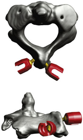
FIGURE 176-8 Computer-generated representation of the atlantoaxial bony anatomy after C2 translaminar screw placement.
Researchers in a 20-patient series who used this stabilization technique reported a 100% fusion rate with no complications at the 1-year follow-up examinations.56 Furthermore, biomechanical studies have shown that stabilization with C2 laminar screws is equivalent to that achieved with Magerl’s and the C1-C2 rod cantilever techniques and hence can be used as an alternative if indicated.58,59
Odontoid Screw Technique
In contrast to posterior C1-C2 fixation, an anterior approach preserves normal C1-C2 articulation and hence rotational movement, provides immediate fixation, and promotes healing. Odontoid screw placement has been made easier and safer with the evolution of retraction systems that provide access to the anterior base of the C2 vertebral body, and these systems offer an optimal trajectory for screw placement for type II fractures (Fig. 176-9).60–64 Multiple different retractor systems are available. At my institution, my colleagues and I prefer to perform this operation using a modified tubular retractor with a 30° beveled end. This system is simple to use, improves visualization of structures, and provides more protection of the soft tissues surrounding the cervical spine.
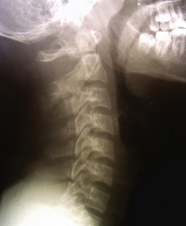
FIGURE 176-9 Lateral cervical spine x-ray showing a type II odontoid fracture with 2-mm rostral displacement.
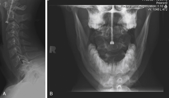
A right-handed surgeon will approach the cervical spine from the right side of the patient, as this is more comfortable, and vice versa for a left-handed surgeon. An incision is made at approximately the level of the C5-C6 disc space, starting at midline and carrying to the right side. The soft tissues are dissected in the standard fashion for an anterior cervical approach to the cervical spine. Handheld retractors are used to obtain cephalad dissection and exposure of the C2-C3 disc space. The modified retractor tube is then centered over the C2-C3 disc space (Fig. 176-10A). With the retractor placed against the anterior cervical spine, the soft tissues are retracted laterally and medially and are thus protected along the length of the retractor from the surface of the spine to the skin. The position of the retractor is corroborated by fluoroscopy (Fig. 176-9B), and the tube is secured to a bed-mounted articulating arm contralateral to the surgeon. In contrast to use of the anterior Caspar or Apfelbaum retractor system (both from Aesculap Implant Systems, Center Valley, PA, USA), no longus colli dissection is required for placement of the retractor.

With the retractor in position, the soft tissues are held out of the operative field and the C2-C3 disc space is well-illuminated. The remainder of the operation progresses in the standard fashion. A 6-mm diamond burr is used to create a trough in the anterior-superior aspect of the C3 vertebral body. A drill guide is placed down the tube retractor, and a Kirschner wire is driven through the base of C2, across the fracture site, and into the dens. A cannulated tap is then used to prepare the screw trajectory, and a cannulated lag screw is threaded over the Kirschner wire. The odontoid tip is captured, and the fracture is reduced, as corroborated by fluoroscopy (Fig. 176-11A, B).
Conclusion
A variety of fixation techniques have been used for the fixation and stabilization of the atlantoaxial junction. The initial wiring techniques are technically less demanding, but one of their main disadvantages is the requirement of postoperative external halo fixation for acceptable fusion rates. Screw fixation techniques require greater technical agility but allow for immediate fixation without the need for prolonged postoperative orthoses. It is essential to be familiar with all aspects of atlantoaxial fixation techniques, their indications and limitations, potential bailout techniques, and the use of one’s surgical judgment and experience to determine the best course of action for each patient.
Anderson L.D., D’Alonzo R.T. Fractures of the odontoid process of the axis. J Bone Joint Surg Am. 1974;56:1663-1674.
Boden S.D., Dodge L.D., Bohlman H.H., Rechtine G.R. Rheumatoid arthritis of the cervical spine: a long-term analysis with predictors of paralysis and recovery. J Bone Joint Surg Am. 1993;75:1282-1297.
Dickman C.A., Sonntag V.K.H. Injuries involving the transverse atlantal ligament: classification and treatment guidelines based upon experience with 39 injuries. Neurosurgery. 1997;40:886-887.
Dickman C.A., Greene K.A., Sonntag V.K.H. Injuries involving the transverse atlantal ligament: classification and treatment guidelines based upon experience with 39 injuries. Neurosurgery. 1996;38:44-50.
Dvorak J., Panjabi M., Gerber Wichmann W. CT-functional diagnostics of the rotatory instability of upper cervical spine. 1. An experimental study on cadavers. Spine (Phila Pa 1976). 1987;12:197-205.
Effendi B., Roy D., Cornish B., et al. Fractures of the ring of the axis: a classification based on the analysis of 131 cases. J Bone Joint Surg Br. 1981;63-B:319-327.
Fehlings M.G., Cooper P., Errico T. Rheumatoid arthritis in the cervical spine. In: Cooper P., editor. Neurosurgical Topics: degenerative Disease of the Cervical Spine. Rolling Meadows, IL: American Association of Neurological Surgeons; 1992:125-139.
Lawsing J.F.3rd, Hohl M. Tears of the transverse ligament of the atlas: a clinical and biomechanical study. J Bone Joint Surg Am. 1974;56:1683-1691. Fielding JW, Cochran GVB
Fielding J.W., Hensinger R.N., Hawkins R.J. Os odontoideum. J Bone Joint Surg Am. 1980;62:376-383.
Greene K.A., Dickman C.A., Marciano F.F., et al. Transverse atlantal ligament disruption associated with odontoid fractures. Spine (Phila Pa 1976). 1994;19:2307-2314.
Hadley MN. Chapter 19. Os odontoideum. In: Guidelines for the Management of Acute Cervical Spine and Spinal Cord Injuries Neurosurgery. 2002;50(suppl 3):S148–S155.
Hadley M.N., Browner C.M., Liu S.S., Sonntag V.K.H. New subtype of acute odontoid fractures (type IIA). Neurosurgery. 1988;22:67-71.
Hadley M.N., Dickman C.A., Browner C.M., Sonntag V.K.H. Acute axis fractures: a review of 229 cases. J Neurosurg. 1989;71:642-647.
Jefferson G. Fracture of the atlas vertebra: report of four cases, and a review of those previously recorded. Br J Surg. 1920;7:407-422.
Jefferson G. Remarks on fractures of the first cervical vertebra. Br Med J. 1927;2:153-157.
Kawashima M., Tanriover N., Rhoton A.L.Jr., et al. Comparison of the far lateral and extreme lateral variants of the atlanto-occipital transarticular approach to anterior extradural lesions of the craniovertebral junction. Neurosurgery. 2003;53:662-675.
Klimo P.Jr., Kan P., Rao G., et al. Os odontoideum: presentation, diagnosis, and treatment in a series of 78 patients. J Neurosurg Spine. 2008;9:332-342.
Matsui H., Imada K., Tsuji H. Radiographic classification of os odontoideum and its clinical significance. Spine (Phila Pa 1976). 1997;22:1706-1709.
Mikulowski P., Wollheim F.A., Rotmil P., Olsen I. Sudden death in rheumatoid arthritis with atlanto-axial dislocation. Acta Med Scand. 1975;198:445-451.
Parker S.L., McGirt M.J., Garcés-Ambrossi G.L., et al. Translaminar versus pedicle screw fixation of C2: comparison of surgical morbidity and accuracy of 313 consecutive screws. Neurosurgery. 2009;64(5 Suppl. 2):343-349.
Penning L., Wilmink J.T. Rotation of the cervical spine: a CT study in normal subjects. Spine (Phila Pa 1976). 1987;12:732-738.
Sciubba D.M., Noggle J.C., Vellimana A.K., et al. Radiographic and clinical evaluation of free-hand placement of C-2 pedicle screws: clinical article. J Neurosurg Spine. 2009:1115-1122.
Spierings E.L., Braakman R. The management of os odontoideum: analysis of 37 cases. J Bone Joint Surg Br. 1982;64:422-428.
Stewart G.C.Jr., Gehweiler J.A.Jr., Laib R.H., Martinez S. Horizontal fracture of the anterior arch of the atlas. Radiology. 1977;122:349-352.
Weissman B.N., Aliabadi P., Weinfeld M.S., et al. Prognostic features of atlantoaxial subluxation in rheumatoid arthritis patients. Radiology. 1982;144:745-751.
1. Penning L., Wilmink J.T. Rotation of the cervical spine: a CT study in normal subjects. Spine (Phila Pa 1976). 1987;12:732-738.
2. Kawashima M., Tanriover N., Rhoton A.L.Jr., et al. Comparison of the far lateral and extreme lateral variants of the atlanto-occipital transarticular approach to anterior extradural lesions of the craniovertebral junction. Neurosurgery. 2003;53:662-675.
3. Anderson L.D., D’Alonzo R.T. Fractures of the odontoid process of the axis. J Bone Joint Surg Am. 1974;56:1663-1674.
4. Hadley M.N., Dickman C.A., Browner C.M., Sonntag V.K.H. Acute axis fractures: a review of 229 cases. J Neurosurg. 1989;71:642-647.
5. Hadley M.N., Browner C.M., Liu S.S., Sonntag V.K.H. New subtype of acute odontoid fractures (type IIA). Neurosurgery. 1988;22:67-71.
6. Greene K.A., Dickman C.A., Marciano F.F., et al. Transverse atlantal ligament disruption associated with odontoid fractures. Spine (Phila Pa 1976). 1994;19:2307-2314.
7. Effendi B., Roy D., Cornish B., et al. Fractures of the ring of the axis: a classification based on the analysis of 131 cases. J Bone Joint Surg Br. 1981;63-B:319-327.
8. Stewart G.C.Jr., Gehweiler J.A.Jr., Laib R.H., Martinez S. Horizontal fracture of the anterior arch of the atlas. Radiology. 1977;122:349-352.
9. Jefferson G. Fracture of the atlas vertebra: report of four cases, and a review of those previously recorded. Br J Surg. 1920;7:407-422.
10. Jefferson G. Remarks on fractures of the first cervical vertebra. Br Med J. 1927;2:153-157.
11. Dickman C.A., Greene K.A., Sonntag V.K.H. Injuries involving the transverse atlantal ligament: classification and treatment guidelines based upon experience with 39 injuries. Neurosurgery. 1996;38:44-50.
12. Dickman C.A., Sonntag V.K.H. Injuries involving the transverse atlantal ligament: classification and treatment guidelines based upon experience with 39 injuries. Neurosurgery. 1997;40:886-887.
13. Fielding J.W., Cochran G.V.B., Lawsing J.F.3rd, Hohl M. Tears of the transverse ligament of the atlas: a clinical and biomechanical study. J Bone Joint Surg Am. 1974;56:1683-1691.
14. Dvorak J., Panjabi M., Gerber Wichmann W. CT-functional diagnostics of the rotatory instability of upper cervical spine. 1. An experimental study on cadavers. Spine (Phila Pa 1976). 1987;12:197-205.
15. Fehlings M.G., Cooper P., Errico T. Rheumatoid arthritis in the cervical spine. In: Cooper P., editor. Neurosurgical Topics: degenerative Disease of the Cervical Spine. Rolling Meadows, IL: American Association of Neurological Surgeons; 1992:125-139.
16. Weissman B.N., Aliabadi P., Weinfeld M.S., et al. Prognostic features of atlantoaxial subluxation in rheumatoid arthritis patients. Radiology. 1982;144:745-751.
17. Mikulowski P., Wollheim F.A., Rotmil P., Olsen I. Sudden death in rheumatoid arthritis with atlanto-axial dislocation. Acta Med Scand. 1975;198:445-451.
18. Boden S.D., Dodge L.D., Bohlman H.H., Rechtine G.R. Rheumatoid arthritis of the cervical spine: a long-term analysis with predictors of paralysis and recovery. J Bone Joint Surg Am. 1993;75:1282-1297.
19. Klimo P.Jr., Kan P., Rao G., et al. Os odontoideum: presentation, diagnosis, and treatment in a series of 78 patients. J Neurosurg Spine. 2008;9:332-342.
20. Hadley MN. Chapter 19. Os odontoideum. In: Guidelines for the Management of Acute Cervical Spine and Spinal Cord Injuries Neurosurgery. 2002;50(suppl 3):S148–S155.
21. Matsui H., Imada K., Tsuji H. Radiographic classification of os odontoideum and its clinical significance. Spine (Phila Pa 1976). 1997;22:1706-1709.
22. Spierings E.L., Braakman R. The management of os odontoideum: analysis of 37 cases. J Bone Joint Surg Br. 1982;64:422-428.
23. Fielding J.W., Hensinger R.N., Hawkins R.J. Os odontoideum. J Bone Joint Surg Am. 1980;62:376-383.
24. Dai L., Yuan W., Ni B., Jia L. Os odontoideum: etiology, diagnosis, and management. Surg Neurol. 2000;53:106-109.
25. Lowry D.W., Pollack I.F., Clyde B., et al. Upper cervical spine fusion in the pediatric population. J Neurosurg. 1997;87:671-676.
26. Taggard D.A., Menezes A.H., Ryken T.C. Treatment of Down syndrome-associated craniovertebral junction abnormalities. J Neurosurg. 2000;93(suppl 2):205-213.
27. Wang J., Vokshoor A., Kim S., et al. Pediatric atlantoaxial instability: management with screw fixation. Pediatr Neurosurg. 1999;30:70-78.
28. Gallie W. Fractures and dislocation of the cervical spine. Am J Surg. 1939;46:495-499.
29. Grob D., Crisco J.J.3rd, Panjabi M.M., et al. Biomechanical evaluation of four different posterior atlantoaxial fixation techniques. Spine (Phila Pa 1976). 1992;17:480-490.
30. Menendez J.A., Wright N.M. Techniques of posterior C1-C2 stabilization. Neurosurgery. 2007;60(1 supp1 1):S103-S111.
31. Brooks A.L., Jenkins E.B. Atlanto-axial arthrodesis by the wedge compression method. J Bone Joint Surg Am. 1978;60:279-284.
32. McDonnell D., Harrison S. Posterior atlantoaxial fusion: indications and techniques. In: Hitchon P.W., Traynelis V.C., Renchary S. Techniques in Spinal Fusion and Stabilization. New York, NY: Thieme; 1995:92-106.
33. Dickman C.A., Sonntag V.K., Papadopoulos S.M., Hadley M.N. The interspinous method of posterior atlantoaxial arthrodesis. J Neurosurg. 1991;74:190-198.
34. Holness R.O., Huestis W.S., Howes W.J., Langille R.A. Posterior stabilization with an interlaminar clamp in cervical injuries: technical note and review of the long term experience with the method. Neurosurgery. 1984;14:318-322.
35. Magerl F., Seemann P. Stable posterior fusion of the atlas and axis by transarticular screw fixation in cervical spine. In: Kehr I.P., Weidner A. Cervical Spine. Berlin: Springer-Verlag; 1986:322-327.
36. Moskovich R., Crockard H.A. Atlantoaxial arthrodesis using interlaminar clamps: an improved technique. Spine (Phila Pa 1976). 1992;17:261-267.
37. Wright N., Lauryssen C. Techniques of posterior C1-C2 stabilization. TechNeurosurg. 1998;4:286-297.
38. Madawi A.A., Solanki G., Casey A.T., Crockard H.A. Variation of the groove in the axis vertebra for the vertebral artery: implications for instrumentation. J Bone Joint Surg Br. 1997;79:820-823.
39. Madawi A.A., Casey A.T., Solanki G.A., et al. Radiological and anatomical evaluation of the atlantoaxial transarticular screw fixation technique. J Neurosurg. 1997;86:961-968.
40. Stillerman C.B., Wilson J.A. Atlanto-axial stabilization with posterior transarticular screw fixation: technical description and report of 22 cases. Neurosurgery. 1993;32:948-955.
41. Fuji T., Oda T., Kato Y., et al. Accuracy of atlantoaxial transarticular screw insertion. Spine (Phila Pa 1976). 2000;25:1760-1764.
42. Haid R.W.Jr. C1-C2 transarticular screw fixation: technical aspects. Neurosurgery. 2001;49:71-74.
43. Jeanneret B., Magerl F. Primary posterior fusion C1/2 in odontoid fractures: indications, technique, and results of transarticular screw fixation. J Spinal Disord. 1992;5:464-475.
44. Haid R.W.Jr., Subach B.R., McLaughlin M.R., et al. C1-C2 transarticular screw fixation for atlantoaxial instability: a 6-year experience. Neurosurgery. 2001;49:65-70.
45. Reilly T.M., Sasso R.C., Hall P.V. Atlantoaxial stabilization: clinical comparison of posterior cervical wiring technique with transarticular screw fixation. J Spinal Disord Tech. 2003;16:248-253.
46. Farey I.D., Nadkarni S., Smith N. Modified Gallie technique versus transarticular screw fixation in C1-C2 fusion. Clin Orthop Relat Res. 1999;359:126-135.
47. Wright N.M., Lauryssen C. Vertebral artery injury in C1-2 transarticular screw fixation: results of a survey of the AANS/CNS section on disorders of the spine and peripheral nerves. American Association of Neurological Surgeons/Congress of Neurological Surgeons. J Neurosurg. 1998;88:634-640.
48. Harms J., Melcher R.P. Posterior C1-C2 fusion with polyaxial screw and rod fixation. Spine (Phila Pa 1976). 2001;26:2467-2471.
49. Resnick D.K., Benzel E.C. C1-C2 pedicle screw fixation with rigid cantilever beam construct: case report and technical note. Neurosurgery. 2002;50:426-428.
50. Stokes J.K., Villavicencio A.T., Liu P.C., et al. Posterior atlantoaxial stabilization: new alternative to C1-2 transarticular screws. Neurosurg Focus. 2002;12:E6.
51. Goel A., Laheri V. Plate and screw fixation for atlanto-axial subluxation. Acta Neurochir (Wien). 1994;129:47-53.
52. Sciubba D.M., Noggle J.C., Vellimana A.K., et al. Radiographic and clinical evaluation of free-hand placement of C-2 pedicle screws: clinical article. J Neurosurg Spine. 2009;11:15-22.
53. Ebraheim N., Rollins J.R.Jr., Xu R., Jackson W.T. Anatomic consideration of C2 pedicle screw placement. Spine (Phila Pa 1976). 1996;21:691-695.
54. Leonard J.R., Wright N.M. Pediatric atlantoaxial fixation with bilateral, crossing C-2 translaminar screws: technical note. J Neurosurg. 2006;104(suppl 1):59-63.
55. Wright N.M. Posterior C2 fixation using bilateral, crossing C2 laminar screws: case series and technical note. J Spinal Disord Tech. 2004;17:158-162.
56. Wright N.M. Translaminar rigid screw fixation of the axis: technical note. J Neurosurg Spine. 2005;3:409-414.
57. Parker S.L., McGirt M.J., Garcés-Ambrossi G.L., et al. Translaminar versus pedicle screw fixation of C2: comparison of surgical morbidity and accuracy of 313 consecutive screws. Neurosurgery. 2009;64(5 suppl 2):343-349.
58. Gorek J., Acaroglu E., Berven S., et al. Constructs incorporating intralaminar C2 screws provide rigid stability for atlantoaxial fixation. Spine (Phila Pa 1976). 2005;30:1513-1518.
59. Lapsiwala S.B., Anderson P.A., Oza A., Resnick D.K. Biomechanical comparison of four C1 to C2 rigid fixative techniques: anterior transarticular, posterior transarticular, C1 to C2 pedicle, and C1 to C2 intralaminar screws. Neurosurgery. 2006;58:516-521.
60. Hashizume H., Kawakami M., Kawai M., Tamaki T. A clinical case of endoscopically assisted anterior screw fixation for the type II odontoid fracture. Spine (Phila Pa 1976). 2003;28:E102-E105.
61. Tippets R.H., Apfelbaum R.I. Anterior cervical fusion with the Caspar instrumentation system. Neurosurgery. 1988;22:1008-1013.
62. Hott J.S., Henn J.S., Sonntag V.K.H. A new table-fixed retractor for anterior odontoid screw fixation: technical note. J Neurosurg. 2003;98(suppl 3):294-296.
63. Horgan M.A., Hsu F.P., Frank E.H. A novel endoscopic approach to anterior odontoid screw fixation: technical note. Minim Invasive Neurosurg. 1999;42:142-145.
64. Neugebauer R. Tissue-preserving ventral compression osteosynthesis of dens axis fractures using endoscopy and special instruments] [in German. Unfallchirurg. 1991;94:313-316.
[/level-membership-for-neurology-category][not-level-membership-for-neurology-category]
Chapter 176 Atlantoaxial Instability and Stabilization
The atlantoaxial junction is a delicate anatomic complex that involves an intricate relationship between the atlas and the axis to allow flexion, extension, rotation, and lateral bending.1 The interrelation of osseous, ligamentous, neural elements, and articulations make the atlantoaxial junction vulnerable to instability and potentially devastating neurologic complications. A myriad of surgical treatment options exist, ranging from fixation with and without dorsal surgical fusion and/or internal fixation using screw techniques and/or wiring techniques. This chapter reviews the different atlantoaxial fixation techniques, including their indications, limitations, and complications.
Anatomic Considerations in Treating C1 and C2 Injuries
The atlas supports the globe of the head and has very unique anatomic characteristics that separate it from other vertebrae. It is essentially a bony ring without a body consisting of an anterior arch as well as two lateral masses connected to a posterior arch by two pedicles (Fig. 176-1). The longus colli muscles attach to the anterior arch via a small bony prominence, the anterior tubercle, which is a rudimentary vertebral body. The posterior aspect of the anterior arch has an indentation, the fovea dentis, to serve to accommodate the odontoid process of C2. The posterior arch joins together to form the posterior tubercle over the posterior midline. It is the attachment point for the posterior atlanto-occipital membrane and the rectus capitis posterior minor muscles. The upper aspect of the posterior arch contains the vertebral arteries within the sulcus arteriae vertebralis. The vertebral arteries travel within the sulcus medially before ascending to penetrate the dura. The lateral masses have large, concave superior surfaces to articulate with the occipital condyles. They are directed upward, medially, and backward and form a cup for the corresponding condyle. The inferior surfaces are circular and directed downward and medially to articulate with the superior articulating facet of C2 and form the zygapophyseal joints, which allows flexion-extension, side-bending, and rotational movements. The atlantoaxial joint is the articulation between C1 and C2 and has a range of motion in the transverse plane for rotation. This rotation is facilitated by the odontoid process, which acts as a pivot point for the rotation of C1. The transverse processes project farther laterally than the transverse processes on the adjacent cervical vertebrae. The apex of the transverse process can be felt through the skin between the mastoid process and the angle of the mandible.2 Several muscles attach to it. The superior obliques arise from the upper surface of the transverse process and extend to the occiput, and the levator scapulae, splenius cervicis, and the scalenus medius attach to the inferior and lateral surfaces of the transverse process. The inferior obliques extend from the inferior surface of the transverse processes to the spinous process of C2. The transverse processes also contain the transverse foramina. The atlantoaxial articulation is composed of three synovial joints: the paired lateral mass articulations and the central articulation between the dens and the anterior arch of C1 and the transverse ligament. The transverse ligament attaches just below the medial margin of each superior facet, stretching across the atlantal ring and dividing the vertebral foramen into an anterior part, which receives the dens, and a posterior part, which transmits the spinal cord. The transverse ligament is the major stabilizer at the C1-C2 level. The cruciform ligament consists of the superior and inferior longitudinal fasciculi, which extend to insert into the anterior foramen magnum and the posterior body of the axis, respectively. Other important ligaments include the anterior atlantoaxial ligament, which extends caudally to form the anterior longitudinal ligament in the subaxial spine; the posterior atlantoaxial ligament, which extends caudally to form the ligamentum flavum; the apical ligament, which connects the tip of the dens to the foramen magnum; and the alar ligaments, which extend from the lateral dens to attach to the occipital condyles.
Indications for Fixation
The indications for fixation are described in the following subsections.
Trauma
Because of the fragile nature of the bony and ligamentous components of the upper cervical spine, injuries to this region are common. The mechanisms of injury include flexion, extension, or compressive forces applied to the head during motor vehicle accidents, falls, or sports-related injuries. Trauma to the atlantoaxial complex can lead to significant instability and may require surgical fixation. Fractures of the dens are common injuries requiring fixation. In some cases, these fractures can be treated using an anterior approach, thus sparing motion; in other circumstances, a posterior approach may be indicated.
Odontoid Fractures
Classification
The most widely accepted classification for odontoid fractures is the Anderson and D’Alonzo classification, which is based on the fracture line.3 The criteria for the treatment algorithms for these types of fractures pertain to the fracture line, the amount of displacement, and a concurrent ligamentous injury. It is therefore imperative to perform computed tomography (CT) and MRI for evaluation. Type I is a stable avulsion fracture that involves the tip of the dens and, in general, leaves the ligamentous complex intact. Treatment involves the use of a cervical collar and symptomatic relief. However, it is imperative to evaluate the craniocervical junction with a flexion-extension dynamic study to rule out concomitant ligamentous injury and instability. Type II odontoid fractures are inherently unstable and occur at the junction of the C2 vertebral body and the dens. The treatment options and their union rate vary with the amount of displacement: With less than 6 mm displacement, external halo fixation carries a 93% union rate4; with 6 mm or more displacement or with comminuted fragments of the base of the dens (type IIa), the disunion rate is as high as 75% to 85% and internal fixation needs to be considered.4,5 Type II odontoid fractures can also lead to transverse ligament injury.6 The integrity of the transverse ligament is essential in making the decision to use anterior odontoid screw fixation. If the ligament is intact, one can proceed with odontoid screw fixation; otherwise, a C1-C2 fixation is necessary. The techniques for C1-C2 fusion and for anterior odontoid screw fixation are discussed below. Type III odontoid fractures extend into the cancellous portion of the C2 vertebral body. They are considered unstable fractures and are treated by reduction with skeletal traction as needed and immobilization with a collar or halo. Surgery is indicated if there is persistent disunion after 12 weeks of orthosis use.
Traumatic Spondylolisthesis of the Axis (Hangman’s Fracture)
Traumatic spondylolisthesis of the axis was first described in convicts who were hanged, hence its nickname, Hangman’s fracture. When the convict fell into the rope, the neck was distracted and hyperextended, resulting in rupture of the C2-C3 disc and fracture of C2. Hangman’s fractures account for approximately 7% of all cervical fractures. Today the most common cause of traumatic spondylolisthesis of the axis is a hyperextension-compression injury. This explains the fact that patients who sustain these fractures seldom have neurologic complications. Hangman’s fractures cross the pars interarticularis of C2 and are classified by Effendi et al7 into three types: Type I Hangman’s fractures account for 65% of all traumatic spondylolistheses and consist of a stable, nondislocated fracture with intact C2-C3 disc space, type II involves a ruptured C2-C3 disc with dislocation of the C2, and C2-C3 is unstable. It account for 28% of traumatic spondylolisthesis, and type III adds a unilateral C2-C3 dislocation to the type II definition.
Fractures of the Atlas
Atlas fractures account for approximately 2% to 13% of all cervical spinal injuries and are classified according to Gehweiler and colleagues8 as follows:
• Type I: isolated fracture of the anterior arch of C1
• Type II: isolated fracture of the posterior arch of C1
• Type III: combined anterior-posterior fracture (Jefferson fracture)
Type I fracture is a horizontal avulsion injury of the caudal portion of the anterior arch due to the contraction of the longus colli during hyperextension. Hence the circumferential integrity of the atlas is maintained, and treatment involves symptomatic relief and a collar. With concomitant dens dislocation, the fracture can become unstable, and the algorithm follows that of an odontoid fracture. In type II injuries, the fracture is located in the weakest part of the posterior arch, usually at the sulcus arteriae vertebralis, and it is bilateral. It is a hyperextension and axial loading injury that is usually not accompanied by neurologic deficit, since the osseous structures are pushed outward. A concomitant dens fracture needs to be excluded during the differential diagnosis and treatment is symptomatic. Type III injury, or Jefferson fracture, was first described by Jefferson in the 1920s.9,10 It involves both the anterior and the posterior arch of C1 and can include unilateral and/or bilateral fractures on either arch. Type III is an axial loading injury with lateral displacement of the fragments that can include a concurrent avulsion injury of the transverse ligament. The latter renders a Jefferson fracture unstable. It is therefore imperative to exclude injury of the transverse ligament on the basis of radiographic evidence of a Jefferson fracture. Spence’s rule assumes a rupture of the transverse ligament if the step-off of the lateral masses confirmed by a transoral open-mouth view or by coronal reconstructive CT is at least 7 mm. If the sum is less than 7 mm, a flexion-extension study can be obtained to rule out underlying instability. Types IV and V fractures are rare, stable fractures requiring symptomatic treatment. With transverse process fractures, there is a risk of thrombosis of the vertebral artery. Obtaining an arteriogram may become necessary if there are clinical signs of vertebral artery thrombosis. Patients with all of these injuries need to have follow-up flexion-extension examinations to rule out ligamentous laxity after the fractures have healed.
Isolated Transverse Ligament Injury
Traditionally, Spence’s rule is applied to identify a transverse ligament injury radiographically. More recently, some authors have indicated that MRI is a more sensitive indicator of transverse ligament injury than Spence’s rule.6,11,12 Dickman et al11 classified isolated transverse ligament injuries into two different types based on MRI: type I is an injury of the transverse ligament without concurrent atlantal fracture, and type II involves an avulsion fracture at the insertion of the ligament into the medial aspect of the arch. In their series of 39 patients with axial and atlantal fractures, they concluded that use of Spence’s rule would have missed 60% of transverse ligament injuries (as determined by MRI). They suggested that type I transverse ligament injuries need to be treated with early surgery and favor external halo immobilization for type II fractures.12
Ligamentous Injury
Flexion of the upper cervical spine can lead to ligamentous injuries and subsequent laxity without bony injury. A value greater or equal to 5 mm for the anterior atlantodental interval in adults (normal value, 2 to 4 mm in adults and 7 mm in adult patients with Down syndrome) indicates ligamentous laxity, and a value greater than 10 to 12 mm indicates complete ligamentous destruction.13 Axial rotation of the upper cervical spine is limited by the alar ligaments, and damage to these ligaments increases rotation on the contralateral side by 30%.14 Failure of any of the components of the atlantoaxial ligament complex requires dorsal surgical fusion.
Rheumatoid Arthritis
Rheumatoid arthritis (RA) is a systemic disease that can affect the atlantoaxial junction and subaxial vertebrae. Eighty-eight percent of RA patients have involvement of the C1-C2 junction.15 As many as half of patients with RA develop symptomatic atlantoaxial subluxation, 56% of whom have myelopathy.16 Postmortem examinations have indicated C1-C2 instability as the cause of death in as many as 10% of patients.17 Classic radiographic findings include the staircase phenomenon, which is due to multiple subluxations involving the atlantoaxial and subaxial joints. In general, the following are indications for surgical intervention: spinal cord compression, severe neck symptoms, and marked subluxation. Any combination of two of the following factors also warrants surgery: cervical myelopathy, delayed central motor latency, spinal cord diameter less than 6 mm in a neutral or flexed position observed on an MRI study or less than 10 mm upon flexion, pannus more than 10 mm behind the dens, and anterior atlantodental distance more than 10 mm. Some authors advocate surgical intervention if the posterior atlantodental interval is less than or equal to 14 mm, even without neurologic symptoms.18
Congenital Abnormalities
Any congenital abnormality that prevents optimal development of the osseous (dens) and/or ligamentous structures (cruciate ligament) can lead to atlantoaxial instability. Os odontoideum is a failure of the dens to fuse with the body of the axis and, together with odontoid agenesis, can lead to ligamentous laxity or underdevelopment and hence instability, requiring surgical intervention.19,20
OS Odontoideum
Os odontoideum is an ossicle with smooth circumferential cortical margins that represent the dens without osseous continuity with the body of C2.21,22 The etiology of this entity remains disputed (acquired vs. congenital), but the etiology is of no importance in the treatment algorithms.20 Os odontoideum can be classified as orthotopic and dystrophic. The former defines an ossicle that moves with the anterior arch of C1 and can sublux anterior to the arch,23 and the latter describes an ossicle that is fused to the basion. The natural history of os odontoideum is variable, and no predictive factors for a clinical scenario have been identified. Surgical treatment of os odontoideum correlates with the presence or absence of C1-C2 instability. Patients without neurologic deficits and without C1-C2 instability on flexion-extension can be managed conservatively. Although some patients with instability have been treated nonoperatively, most surgeons advocate operative stabilization and C1-C2 fusion. The concern is that with this constellation there is a higher risk of future spinal cord injury, and several studies have indicated that surgery has merit.24–27 Furthermore, longitudinal radiographic and clinical surveillance is recommended for all conservatively treated patients.23 Screw fixation techniques have the advantage that no postoperative external fixation is required. The last category of etiologies that can lead to instability of the atlantoaxial junction includes infectious and neoplastic processes affecting the C1-C2 junction.
Dorsal Wiring Techniques
Gallie Fusion
Initially described in 1939, the Gallie dorsal wiring fusion technique is a simple surgical fixation method (Fig. 176-2).28 It consists of placement of a medial bone graft between the posterior arch of C1 and the spinous process of C2, with sublaminar wiring around the arch of C1 and looping around the C2 spinous process. For the sublaminar placement of the wire, a 1.2-mm wire is looped into a hook configuration and passed from the inferior aspect of posterior arch of C1 ventrally to the arch of C1 and over the posterior aspect of the arch of C1. Attention should be paid so that no injury to the spinal cord occurs during that process. The loop is then pulled caudally enough to hook it over the spinous process of C2. The arch of C1 and the lamina of C2 are decorticated, and a bone graft in an H configuration is placed over the decorticated area and fixated with the two lateral ends of the wire. The area around the bone graft can then be packed with more cancellous bone. This technique is the simplest and poorest form of biomechanical stabilization. It requires an intact C1 arch, and as such it cannot be used to treat Jefferson fractures or any entities with involvement of the posterior arch of C1, such as infections, tumors, and rheumatoid arthritis. It offers minimal rotational stability and requires postoperative external immobilization.29 Its disunion rate is rather high at 25%, and this technique is most often used to supplement other stabilization methods.30
Brooks-Jenkins Fusion
For the Brooks-Jenkins wiring technique,31 the laminae of C1 and C2 are dissected and two 20-gauge wires are passed under the lamina bilaterally (Fig. 176-3). Two bone grafts are then placed into the lateral interlaminar space on each side, held in place by the wires. As compared to the Gallie technique, this technique allows more rotational stability with higher fusion success rates of up to 93% with the use of a halo postoperatively. This technique has the same contraindication as the Gallie technique and requires an intact C1 posterior arch. In addition, the passage of two wires can result in wider curvature and a “clothesline” compression of the spinal cord.32
