Chapter 34 Anterior Cervical Stabilization in Tumor Surgery
INTRODUCTION
After a vertebral body tumor resection, various methods of interbody grafting are available to accompany anterior plate placement or posterior instrumentation. Ideally the plating system should facilitate placement of the interbody graft in distraction mode, allowing it to become load bearing. Anterior cervical plating provides immediate stability and prevention of graft dislodgement.1,2 It also decreases stress on the graft and eliminates the need for external orthosis.
TECHNIQUES OF PLATING
DIRECTION OF SCREWS
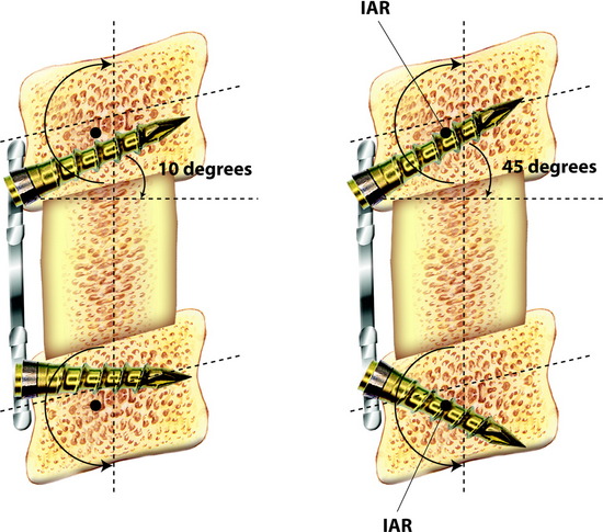
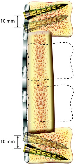
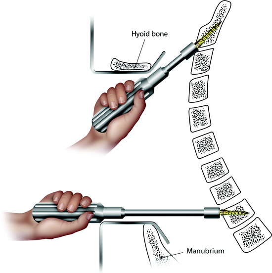
The screw is usually directed 10 to 15 degrees to the horizontal plane.3 However, pull-out tendency is greatest when the screw lies tangent to the arc of rotation around the instantaneous axis of rotation (IAR) and least when the screw lies perpendicular to the arc of rotation around the IAR. The IAR lies toward the ventral inferior aspect of the vertebra but is altered under the influence of a rigid load-bearing device. The screws that lay more perpendicular to the vector of pullout should have greater resistance to pullout (Fig. 34-1).
SELECTION OF THE DEVICE
The classification of devices is according to the motion at the plate-screw interface.4
Unrestricted Backout Device (Bicortical Non-Locked Bone Screw)
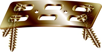
This system has unrestricted backout and is non-locking and non-rigid (Fig. 34-2). The screw angle is determined according to the surgeon’s preference. There is no fixed moment arm, allowing for subsidence of the construct because of the lack of fixation at the screw-plate interface.
Restricted-Constrained Device (Unicortical Locked Bone Screw)
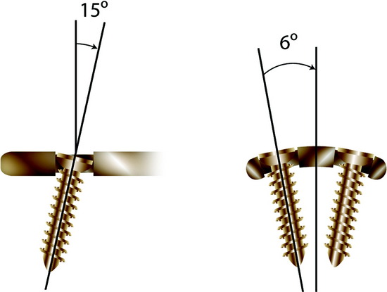
In this system, the screw purchase is unicortical and the screw-plate interface is constrained (Fig. 34-3). There is a predetermined (rigid) screw trajectory in the plate. The locking mechanism prevents screw migration even if screw breakage occurs. The CSLP (cervical spine locking plate) and Orion plate (constrained type) are included in this category.
OTHER OPTIONS IN ANTERIOR CERVICAL PLATING
Telescopic Plate Spacer
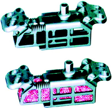
The Telescopic Plate Spacer (TPS; Interpore Cross International, Irvine, CA) is a new option after corpectomy (Fig. 34-5). The device is a titanium cervical plate-interbody spacer hybrid, which can be used in either one-level or two-level corpectomy defects.5 The spacer portion of the device is hollow and may be packed with bone graft. The plate portion of the device can be fixed to the adjacent vertebral bodies with screws. Through the telescopic effect, the device can be expanded to fit corpectomy defects to restore anterior column height and correct kyphotic deformity. By applying distraction anterior to the IAR, the TPS restores lordosis in the cervical spine.
Junctional Plate
This is a technique in which a small anterior cervical plate is fixed at one end of the construct, usually at the lower vertebra graft because dislodgment often occurs at the inferior end of the construct (Fig. 34-6). It overlaps the end of the strut graft-vertebra junction and is able to block the end of the graft so that it does not dislodge anteriorly. An advantage of this system is that it does not create a tension band anteriorly, which would lead to large stresses on the strut graft. It allows load sharing by the graft and lets the graft settle gradually into the endplates without distraction force.
SCREW PURCHASE AT C2
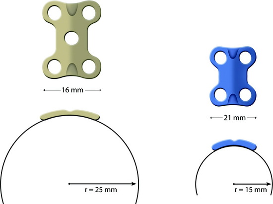
The C2 vertebral body surface is more convex and narrower than the subaxial cervical spine. For plate implantation, the protruding portion should be drilled out. For better fitting of the plate to the vertebral body surface, a narrower and small radius plate may be adequate. It also is better for the screw to be directed less perpendicular to the cortical surface. The more obliquely the screw is directed, the longer is the length of the screw (Fig. 34-7).
SCREW PURCHASE AT T2
Using the usual anterior approach, the T1–2 interspace is the lowest level to reach without a sternotomy. Although the screw insertion angle is nearly horizontal, the angle relative to the disc plane is 20 to 30 degrees. With a horizontal insertion, the screw can be inserted with ideal angulation (Fig. 34-8).
STATIC PLATING VS. DYNAMIC PLATING
Static devices and dynamic devices can be compared with respect to several issues (Fig. 34-9).
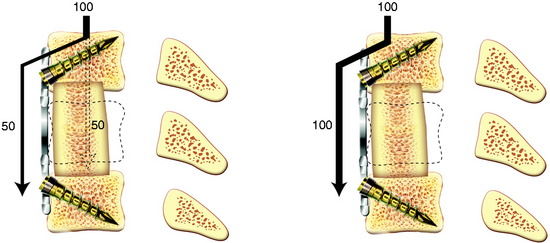
Static Devices (Fixed Plating)
The dynamic plates actually allow more axial load to be transmitted to the strut graft than do the static plates, but the two types of plates are relatively similar in terms of their initial stiffness biomechanically.6 Movement of the screw heads in the elongated holes of the plate also is possible with a combination of movement of the vertebral bodies and axial compression or distraction. Dynamic plating systems are defined as semiconstrained and are characterized by the inherent motion that exists between some of their components. A dynamic plating system functions as a load-sharing (nonconstrained) rather than a load-bearing (constrained) device. This system is designed to provide some resistance to subsidence in the early phase of graft incorporation, while maintaining the most effective biomechanical function of an anterior plate as a tension band. It allows for loading to be present across the remodeling bone graft later in the course of bone healing and enables stress to fortify the fusion as predicted by Wolff’s law.7
HARDWARE FAILURE IN ANTERIOR CERVICAL PLATING
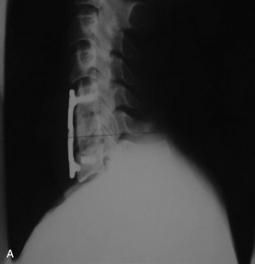
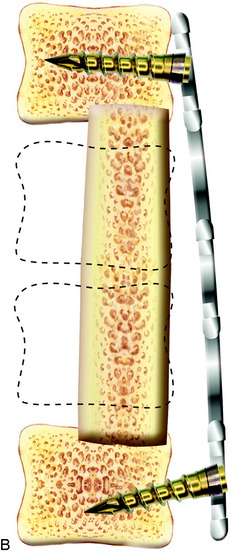
Fig. 34-10 A, Hardware failure caused by screw breakage. B, Hardware failure caused by screw backout.
IS ANTERIOR PLATING ENOUGH AFTER A CORPECTOMY?
After a one-level corpectomy, the failure of the construct is reported to be around 8–9%. The failure rate increases to more than 50% in multilevel corpectomies.8,9
When the corpectomies are planned over two levels, posterior stabilization should be added.10 Biomechanical tests of two-level corpectomies suggest that posterior segmental instrumentation confers significant stability to a multilevel cervical corpectomy regardless of the presence or absence of anterior instrumentation.11
CASE ILLUSTRATION
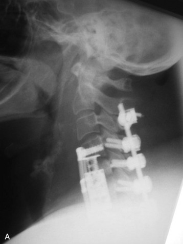
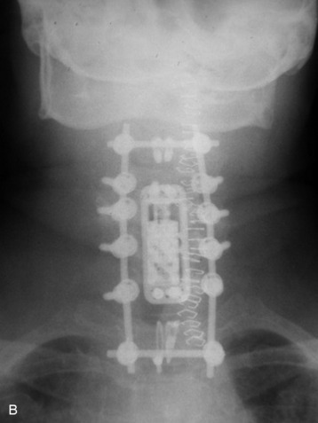
The tumor was resected from the C5 and C6 bodies, and a vertebral body replacement (VBR) cage was inserted. Anterior cervical plating was performed from C4 to C7. Additionally, posterior stabilization was performed from C4 to C7 with lateral mass screw fixation (Fig. 34-11). Two rods were connected with dual transverse connectors, with one at the cephalad end and the other at the caudal end. The transverse connectors were fixed to the spinous process with sublaminar wiring.
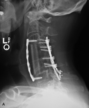
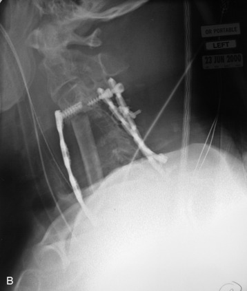
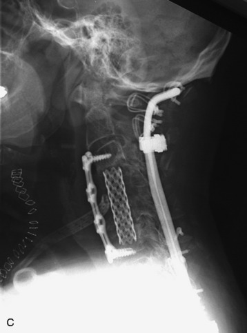
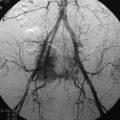
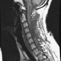
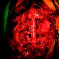
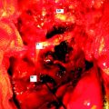
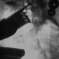
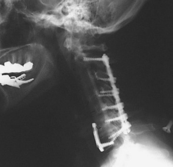
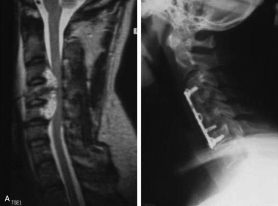
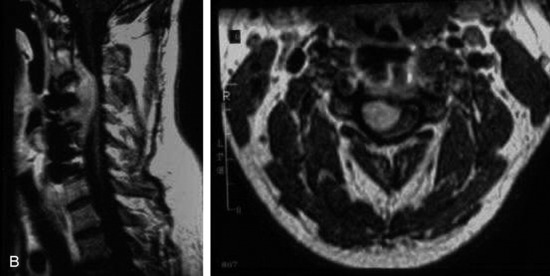
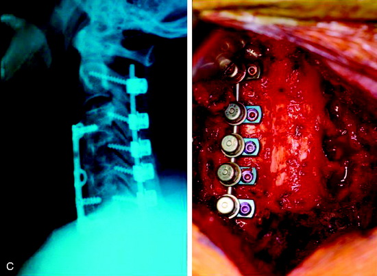
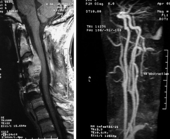
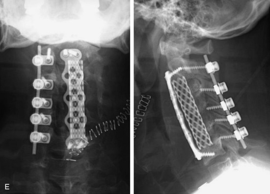
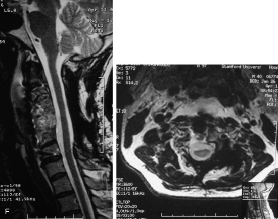
This is a recurrent chordoma case at the cervical spine. The tumor mass was seen at the vertebral body of C4 and C5. At initial surgery, C4 and C5 corpectomies were performed, and anterior plating was applied (Fig. 34-12, A). Three years later, tumor recurrence was detected at the C3, C4, and C5 levels. The mass was formed at the ventral epidural space (Fig. 34-12, B). The second operation was performed with the posterior approach. Total laminectomy was performed from C2 to C6. Additionally, right facet joints were removed at C3, C4, and C5. A ventral epidural mass was removed from the posterior side, and radiation therapy was performed postoperatively. Posterior stabilization was performed with a C2 pedicle screw and C3–6 lateral mass screws (Fig. 34-12, C). Two years later, a second recurrence was detected at C3 and C4. Angiography showed a left vertebral artery obstruction (Fig. 34-12, D). The recurrent tumor began to grow at the C2–3 interspace and formed a large epidural mass, which caused spinal cord compression. The third operation was performed through the anterior route. After wound revision, C3 corpectomy was performed. The epidural mass was removed from the ventral dura. Spinal cord decompression was accomplished completely. A mesh cage filled with allograft bone was inserted into the long corpectomy site and plating was applied (Fig. 34-12, E). The follow-up magnetic resonance image (MRI) showed no recurrence after 1 year (Fig. 34-12, F).
GRAFT FAILURE AFTER CERVICAL CORPECTOMY
STRUT GRAFT INSERTION TECHNIQUE IN ANTERIOR CERVICAL FUSION SURGERY
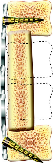
Although successfully used, long strut grafts are vulnerable to dislodgment, displacement, fracture, and nonunion, which can require revision surgery; thus, meticulous preparation of the vertebral endplate, along with exact sizing and harvesting of the bone graft with plating, are essential for successful outcomes. For prevention of graft dislodgement, careful technique in preparing the bony endplate is essential. The aggressive removal of the bone endplate is avoided (Fig. 34-14).
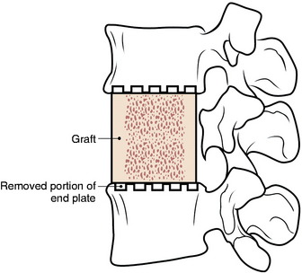
The superior and inferior vertebral recipient sites are prepared with the burr to match the ends of the graft (Fig. 34-15). The anterior and posterior vertebral cortical ridges are preserved to prevent extrusion or posterior migration of the strut graft placement. The graft is placed into the trough and the ends are countersunk into position before the intervertebral distractor is released.
MANAGEMENT OF STRUT GRAFT FAILURE
Graft fracture is more likely to occur when the graft is harvested with an osteotome instead of a saw. If the bone is minimally displaced and there is no kyphotic deformity, the application of a halo vest and close observation can be attempted. In contrast, in the case of graft collapse, the resultant kyphosis and loss of contact of the graft and the vertebral body necessitate the revision of the strut graft and instrumentation. This usually means obtaining a longer graft and extending the fusion one more level. Supplemental posterior stabilization is recommended when the bone quality is not stable.12
CASE ILLUSTRATION
For this patient, C4–5 total corpectomy was performed, and the upper half of the C6 vertebral body was removed. A fibular strut graft was inserted, and anterior plating was performed. Additionally, posterior stabilization was performed from C3 to C6. Several months later, graft dislodgement was seen. The revision operation was performed at the anterior side. The graft was changed to mesh with autograft bone, and plating was added. At the posterior side, the lateral mass plate was removed and long-segment occipital and sublaminar wiring was applied (Fig. 34-16).