Chapter 2 Airway Imaging
Principles and Practical Guide
II Imaging Modalities
A Conventional Radiography (Plain Film)
Wilhelm Conrad Roentgen, a German physicist, discovered x-rays on November 8, 1895, while studying the behavior of cathode rays (electrons) in high-energy cathode ray tubes. By serendipity, he noticed that a mysterious ray that escaped the cathode tube penetrated objects differently, and he named this the x-ray. For his work, he was awarded the first Nobel Prize for Physics in 1901.1
X-rays are a type of electromagnetic radiation; as the name implies, they transport energy through space as a combination of electric and magnetic fields. Other types of electromagnetic radiation include radio waves, radiant heat, and visible light. In diagnostic radiology, the predominant energy source used for imaging is ionizing radiation (i.e., alpha, beta, gamma, and x-rays). The science of electromagnetic waves and x-ray generation is very complex and exceeds the scope of this text. In principle, x-rays are produced by energy conversion as a fast stream of electrons is suddenly decelerated in an x-ray tube.2 The localized x-ray beam that is produced passes through the part of the body being studied. The final image is dependent on the degree of attenuation of the beam by matter.
Attenuation is the reduction in the intensity of the beam as it traverses matter of different constituents. It is caused by absorption or deflection of photons from the beam. The transmitted beam determines the final image, which is represented in shades of gray.3–5 The lightest or brightest area on the film or image represents the greatest attenuation of the beam by tissue and the least amount of beam transmitted to film. For example, bone is a high-density material that attenuates much of the x-ray beam; images of bone on x-ray films are very bright or white. A plain film image is a one-dimensional collapsed or compressed view of the body part being imaged. This information can also be presented in a digital format without the use of traditional x-ray films.
B Computed Tomography
After the discovery of x-rays, it became apparent that images of the internal structures of the human body could yield important diagnostic information. However, the usefulness of x-ray studies is limited because they project a three-dimensional (3-D) object onto a two-dimensional display. With x-rays, the details of internal objects are masked by the shadows of overlying and underlying structures. The goal of diagnostic imaging is to bring forth the organ or area of interest in detail while eliminating unwanted information. Various film-based traditional tomographic techniques were developed, culminating in the creation of computerized axial tomography or computed tomography (CT).6 The first clinically viable CT scanner was developed by Hounsfield and commercially marketed by EMI Limited (Middlesex, England) for brain imaging in the early 1970s.7 Since then, several generations of CT scanners have been developed.
As with conventional plain film radiography, CT technology requires x-rays as the energy source. Whereas conventional radiography employs a single beam of x-rays from a single direction and yields a static image, CT images are obtained with the use of multiple collimated x-ray beams from multiple angles, and the transmitted radiation is counted by a row or rows of detectors. The patient is enclosed in a gantry, and a fan-shaped x-ray source rotates around the patient. The radiation counted by the detectors is analyzed with the use of mathematical equations to localize and characterize tissues by density and attenuation measurements. A single cross-sectional image is produced with one rotation of the gantry.6 The gantry must then “unwind” to prepare for the next slice while the table carrying the patient moves forward or backward by a distance that is predetermined by slice thickness. An intrinsic limitation of this technique is the time required for moving the mechanical parts.
The introduction of slip-ring technology in the 1990s and the development of faster computers, high-energy x-ray tubes, and multidetectors enabled continuous activation of the x-ray source without having to unwind the gantry and also allowed continuous movement of the tabletop. This process, known as helical CT, is used in the latest generation of CT scanners. Because the information acquired using helical CT is volumetric, in contrast to the single slice obtained with conventional CT, the entire thorax or abdomen can be scanned in a single breath-hold. Volumetric information makes it possible to identify small lesions more accurately and allows better 3-D reformation. Because of the higher speed of data acquisition, misregistration and image degradation caused by patient motion are no longer significant concerns. This is especially important when scanning uncooperative patients and trauma victims. The absorbed radiation dose used in multidetector helical CT (as compared with conventional single-detector row CT) is dependent on the scanning protocol and varies with the desired high-speed or high-quality study.8
C Magnetic Resonance Imaging
MRI has become one of the most widely used imaging modalities in diagnostic radiology. In contrast to conventional radiography and CT, MRI uses no ionizing radiation. Instead, imaging is based on the resonance of the atomic nuclei of certain elements such as sodium, phosphorus, and hydrogen in response to radio waves of the same frequency produced in a static magnetic field environment. Current clinical MRI units use protons from the nuclei of hydrogen atoms to generate images because hydrogen is the most abundant element in the body. Every water molecule contains two hydrogen atoms, and larger molecules, such as lipids and proteins, contain many hydrogen atoms. Powerful electromagnets are used to create a magnetic field, which influences the alignment of protons in hydrogen atoms in the body. When radio waves are applied, protons are knocked out of natural alignment, and when the radio wave is stopped, the protons return to their original state of equilibrium, realigning to the steady magnetic field and emitting energy, which is translated into weak radio signals. The time it takes for the protons to realign, referred to as a relaxation time, is dependent on the tissue composition and cellular environment.9 The different relaxation times and signal strengths of the protons are processed by a computer, generating diagnostic images. With MRI, the chemical and physical properties of matter are examined at the molecular level. The relaxation times for each tissue type, designated T1 and T2, are expressed as constants at a given magnetic field strength. Imaging that optimizes T1 or T2 characteristics is referred to as T1-weighted or T2-weighted imaging, respectively. Tissue response to pathologic processes usually includes an increase in bound water (edema), which lengthens the T2 relaxation time and appears as a bright focus on T2-weighted images.9
III Basics of Plain Film Interpretation
A Cervical Spine Radiography
1 General Technique, Anatomy, and Basic Interpretation
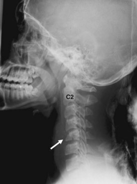
The most common indications for obtaining cervical spine radiographs in today’s medical practice are for the evaluation of trauma, spinal stability, and cervical spondylosis and in the search for radiopaque foreign bodies. Different views of the cervical spine are tailored to each clinical need. The most common views are the lateral, anteroposterior (AP), open-mouth odontoid, oblique, and pillar views (Fig. 2-1). In acute cervical spine injury, cross-table lateral, AP, and open-mouth odontoid views are recommended. A lateral view reveals the majority of injuries (Fig. 2-2); however, patients who are rendered quadriplegic by severe ligamentous injuries may demonstrate a normal lateral cervical spine radiograph. When the AP and then the open-mouth odontoid views are added to the cross-table lateral view of the cervical spine, the sensitivity of detecting significant injury is increased from 74% to 82% and then to 93%.10 In today’s practice, cross-sectional imaging (i.e., CT of the spine) has become a mainstay in the evaluation of the cervical spine, especially in the setting of acute trauma. MRI is particularly useful in evaluating the spinal cord.
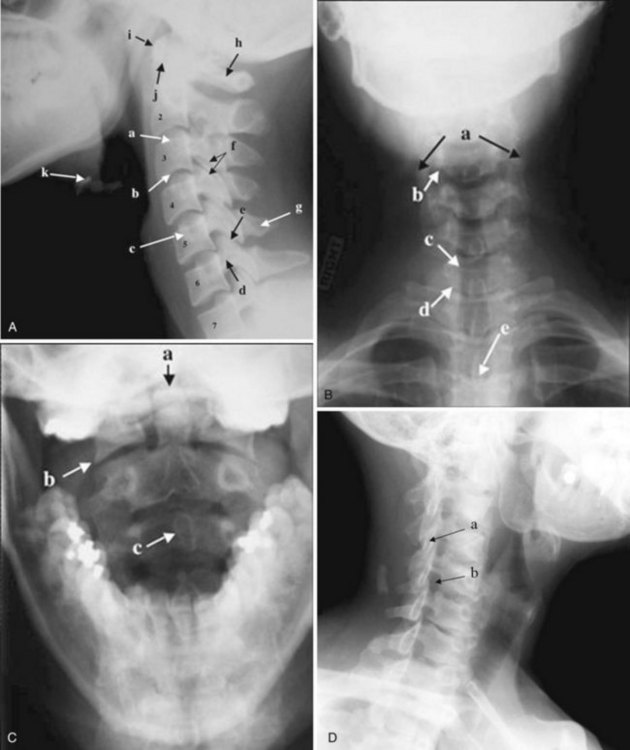
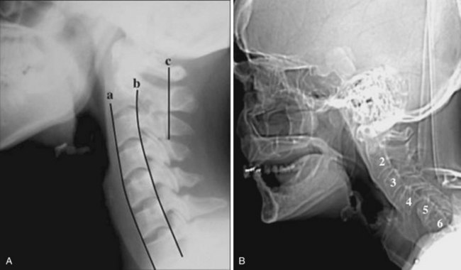
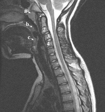
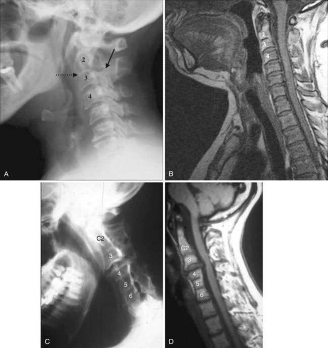
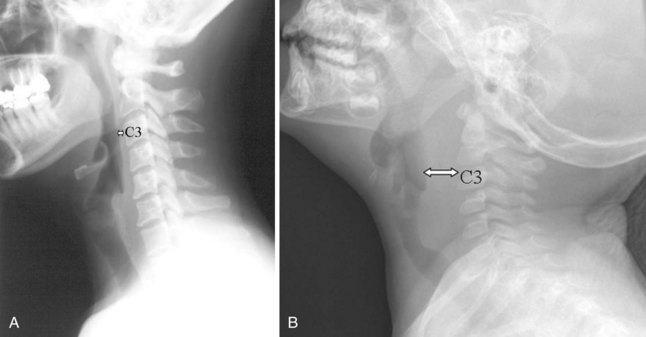
In brief, a normal lateral cervical radiograph should demonstrate seven intact vertebrae and normal alignment of the anterior and posterior aspects of the vertebral bodies. This is especially important for trauma victims, because 7% to 14% of fractures are known to occur at the C7 or C7-T1 level.11 The posterior vertebral body line is more reliable and must be intact. The anterior vertebral line is often encumbered by the presence of anterior osteophytes. Normal facet joints overlap in an orderly fashion, similar to shingles on a rooftop. The spinolaminar line, which is the dense cortical line representing the junction of the posterior laminae and the posterior spinous process, is uninterrupted. Relative uniformity of the interlaminar (interspinous) distances should be observed. The posterior spinal line (i.e., posterior cervical line), an imaginary line extending from the spinolaminar line of the atlas to C3 (Fig. 2-3), should demonstrate a continuous curve in parallel to the posterior vertebral body line; the distance between the two correlates with the spinal canal diameter.12
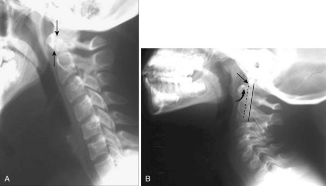
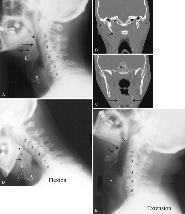
The anatomy and integrity of the craniocervical junction are crucial to the anesthesiologist. To achieve successful and safe endotracheal intubation, the anterior atlantodental interval (AADI), the vertical and anterior-posterior position of the dens, and the degree of extension of the head on the neck must be considered. The anterior arch of C1 bears a constant relationship to the dens; this is the AADI or predental space. It is defined as the space between the posterior surface of the anterior arch of C1 and the anterior surface of the dens. In flexion, because of the physiologic laxity of the cervicocranial ligaments, the anterior tubercle of the atlas assumes a more normal-appearing relationship to the dens, and the AADI increases in width, greater rostrally than caudally. In children and with flexion in adults, the AADI is normally about 5 mm. In adults, it is generally accepted that the AADI is 3 mm or less (Fig. 2-4).12
The bony structures of the atlantoaxial joint provide mobility (e.g., rotational movement) rather than stability. Therefore, the ligaments play a significant role in stability. The most important ligaments in the upper cervical spine are the transverse ligament, the alar ligaments, and the tectorial membrane. If the transverse ligament is disrupted and the alar and apical ligaments remain intact, up to 5 mm of movement at the atlantoaxial joint can be seen.13 If all the ligaments have been disrupted, the AADI can measure 10 mm or larger. In atlantoaxial subluxation, the dens is invariably displaced posteriorly, which causes narrowing of the spinal canal and potential impingement of the spinal cord. The space available for the spinal cord is defined as the diameter of the spinal canal as measured in the AP plane, at the C1 level, that is not occupied by the odontoid process. In the normal spine, this space is approximately 20 mm.13
2 Pertinent Findings and Pathology
a Pseudosubluxation and Pseudodislocation
Pseudosubluxation and pseudodislocation are terms applied to the physiologic anterior displacement of C2 on C3 that is frequently seen in infants and young children (Fig. 2-5). Physiologic anterior displacement of C2 on C3 and of C3 on C4 occurs in 24% and 14%, respectively, of children up to 8 years of age.14
b Congenital and Developmental Anomalies
Occipital Fusion of C1
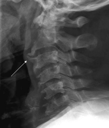
Important to rigid laryngoscopy and endotracheal intubation is the distance between the occiput and the posterior tubercle of C1, known as the atlanto-occipital distance (Fig. 2-6), which is quite variable from individual to individual. Head extension is limited by the abutment of the occiput to the posterior tubercle of C1. It has been proposed that a shorter atlanto-occipital distance decreases the effectiveness of head extension and contributes to difficult intubation.13,15 Occipitalization of C1 with the occiput (atlanto-occipital fusion) not only limits head extension but also adds stress to the atlantoaxial joint. Although the majority of head extension occurs at the atlanto-occipital joint, some extension can also occur at C1-C2.15 Nichol and Zuck observed that in patients with limited or no extension possible at the atlanto-occipital joint, general extension of the head actually brings the larynx “anterior,” thus limiting the visibility of the larynx on laryngoscopy.15
Nonfusion of Anterior and Posterior Arches Of C1
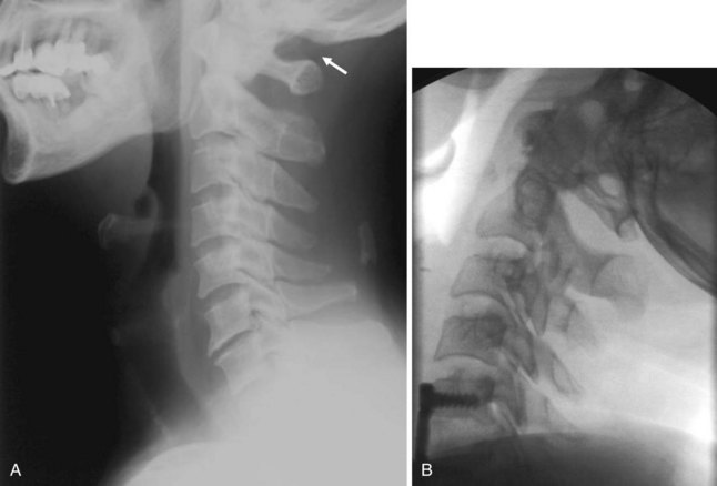
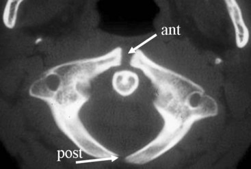
Ossification of the atlas begins with the lateral masses during intrauterine life. At birth, neither the anterior nor the posterior arches are fused. Fusion of the anterior arch is complete between 7 and 10 years of age. During the second year, the center of the posterior tubercle appears, and by the end of the fourth year, the posterior arch becomes complete.12 Nonfusion of the anterior or the posterior arch, or both, exists as a normal variant in adults and should not be mistaken for fracture (Fig. 2-7).
Pseudofractures of C2 and Dens
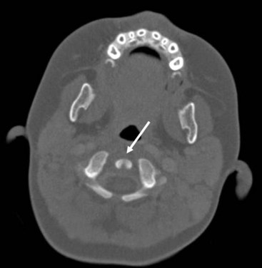
The dens ossifies from two vertically oriented centers that fuse by the seventh fetal month. Cranially, a central cleft separates the tips of these ossification centers (Fig. 2-8), and it can mimic a fracture if ossification is incomplete. The ossiculum terminale, the ossification center for the tip of the dens, may be visible on plain films, conventional tomograms, or CT scans and unites with the body by age 11 or 12 years. Failure of the ossiculum terminale to develop or failure to unite with the dens may result in a bulbous cleft dens tip. A nonunited terminal dental ossification center, called the os terminale, may be mistaken for a fracture of the odontoid tip.
Hypoplasia of C2
The position and anatomy of the dens with respect to the anterior arch of C1 and the foramen magnum are worthy of attention. Congenital anomalies of the odontoid process, such as hypoplasia, can result in a loss of the buttressing action of the dens during extension and subsequent compression of neural elements. Examples of conditions that are associated with odontoid hypoplasia are the Morquio, Klippel-Feil, and Down syndromes; neurofibromatosis; dwarfism; spondyloepiphyseal dysplasia; osteogenesis imperfecta; and congenital scoliosis.13,16 Patients with these conditions are predisposed to atlantoaxial subluxation and craniocervical instability, and hyperextension of the head for intubation should be avoided. In addition, congenital fusion of C2 and C3 (Fig. 2-9), whether occurring as an isolated anomaly or as part of Klippel-Feil syndrome, places added stress at the C1-C2 junction.
c Acquired Pathology
Cervical Spondylosis
Cervical spine radiographs are obtained for the evaluation of cervical spondylosis (Fig. 2-10). The hypertrophic bone changes associated with this condition are well depicted on radiographic studies. Large anterior osteophytes that project forward may cause dysphagia and difficult intubation. The bone canal and neural foramina are assessed for stenosis; if stenosis is present, precautions can be taken when hyperextending the neck and positioning the patient to avoid exacerbation of baseline neurologic symptomatology. Calcification and ossification are well depicted on radiographic studies.
Ossification of the anterior longitudinal ligament and diffuse idiopathic skeletal hyperostosis have been reported as causes of difficult intubation.17 This can be readily appreciated on plain films. Another condition that may signal difficult intubation is calcification of the stylohyoid ligament (Fig. 2-11).18
Inflammatory Arthropathies
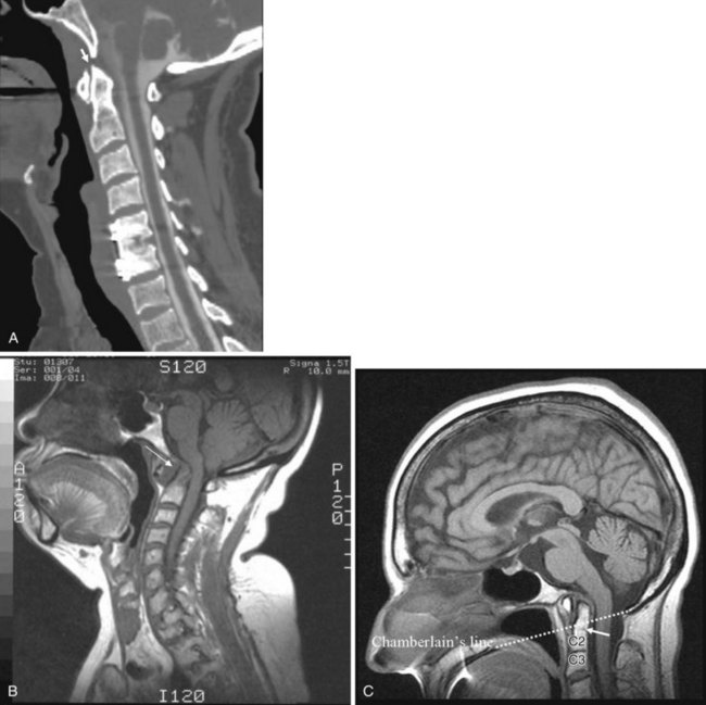
Inflammatory arthropathies involving the atlantoaxial joint with subluxation are classically seen in patients with rheumatoid arthritis or ankylosing spondylitis. However, the underlying causes of atlantoaxial subluxation are quite different in these two entities. Ankylosing spondylitis is characterized by progressive fibrosis and ossification of ligaments and joint capsules. In rheumatoid arthritis, bone erosion, synovial overgrowth, and destruction of the ligaments occur. Patients with rheumatoid arthritis are not only susceptible to AP subluxation at the C1-C2 junction but also at risk for vertical subluxation of the dens. Whether this condition is referred to as “cranial settling,” superior migration of the odontoid process, or basilar invagination, the end result is the same.12 The odontoid process protrudes above the foramen magnum, narrowing the available space for the spinal cord and potentially leading to cord compression with the slightest head extension (Fig. 2-12).13
In response to the effective foreshortening of the spine that occurs secondary to the superior migration of the odontoid process from inflammatory or degenerative disease, there is acquired rotational malalignment between the spine and larynx.19 The larynx and the trachea, because they are semirigid structures and as a result of the tethering effect of the arch of the aorta as it passes posteriorly over the left main bronchus, are predictably displaced caudally, deviated laterally to the left, rotated to the right, and anteriorly angulated. The effective neck length can be affected by superior migration of the dens, severe spondylosis with loss of disc space, or iatrogenic causes secondary to surgery. The soft tissues of the pharynx become more redundant owing to the relative shortening of the neck, which further obscures the view of the larynx. On laryngoscopy, the vocal cords are rotated clockwise. A rotated airway is suspected when the frontal view of the cervical spine demonstrates a deviated tracheal air column.
d Anthropologic Measurements
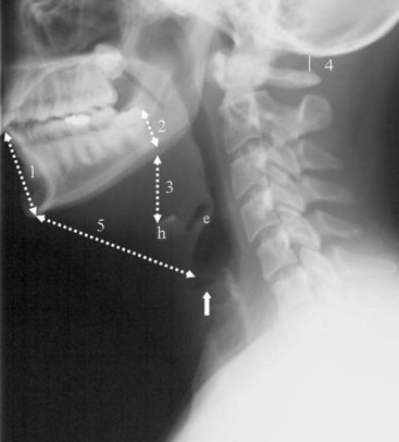
Historically, bony landmarks other than the spine that can be appreciated on a lateral cervical spine radiograph have been used in the anesthesia arena to preoperatively predict difficult laryngoscopy and endotracheal intubation on the basis of anatomic factors. Mandibular size, the ratios of the various measurements, and their relationship to the hyoid bone have been proposed as predictors of difficult laryngoscopy (Fig. 2-13).20 These measurements are meant to reflect the oral capacity, the degree of mouth opening, and the level of larynx.21,22 It is apparent that the causes of difficult laryngoscopy and endotracheal intubation are multifactorial. Combined with the clinical examination, anatomic measurements and findings assessed by x-ray studies can help alert the anesthesiologist to a potentially difficult airway. In this way, difficult laryngoscopy and endotracheal intubation can be anticipated and not unexpected.
B Soft Tissue Neck Radiography
1 General Technique, Anatomy, and Basic Interpretation
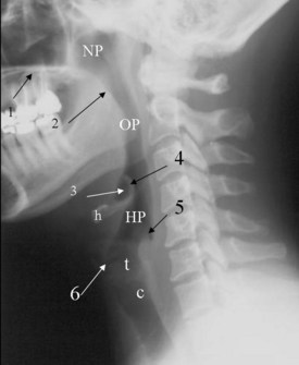
The lateral cervical spine study with bone and soft tissue technique allows an incidental view of the aerodigestive tract and a gross assessment of the overall patency of the airway. Useful ossified cartilage or bony landmarks of the pharynx and larynx that can be appreciated on the lateral neck radiograph are the hard palate, hyoid bone, thyroid, and cricoid cartilages (Fig. 2-14). The hard palate is a bony landmark used to separate the nasopharynx from the oropharynx. The larynx can be thought of as being suspended from the hyoid bone. Muscles acting on the hyoid bone elevate the larynx and provide the primary protection from aspiration. The largest cartilage in the neck is the thyroid cartilage, which along with the cricoid cartilage acts as a protective shield for the inner larynx. The cricoid cartilage is the only complete cartilaginous ring in the respiratory system. It is located at the level where the larynx ends and the trachea begins.
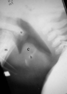
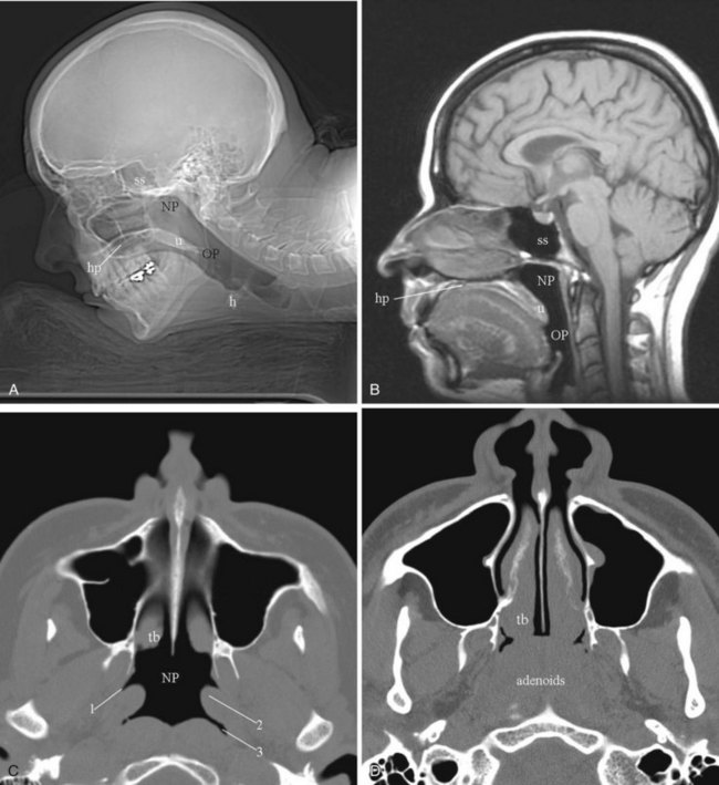
Normal air-filled structures seen on lateral plain films are the nasopharynx, oropharynx, and hypopharynx. Air in the pharynx outlines the soft palate, uvula, base of the tongue, and nasopharyngeal airway (Fig. 2-15). Any sizable soft tissue pathology results in deviation or effacement of the airway. The tongue constitutes the bulk of the soft tissues at the level of the oropharynx. In children, and sometimes in adults, prominent lymphatic tissues such as adenoids and palatine tonsils may encroach on the nasopharyngeal and oral airways. Lingual tonsils are located at the base of the tongue above the valleculae, which are air-filled pouches between the tongue base and the free margin of the epiglottis.
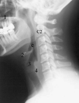
The epiglottis is an elastic fibrocartilage shaped like a flattened teardrop or leaf that tapers inferiorly and attaches to the thyroid cartilage. The epiglottis tends to be more angular in infants than in adults. During the first several years of life, the larynx changes its position in the neck.23,24 The free edge of the epiglottis in neonates is found at or near the C1 level, and the cricoid cartilage, representing the most caudal portion of the larynx, is at the C4-C5 level. By adolescence, the epiglottis is found at the C2-C3 level and the cricoid is at the C6 level. The adult epiglottis is usually seen at the C3 level, with the cricoid at C6-C7. However, the position of these structures in the normal population varies by at least one vertebral body level.
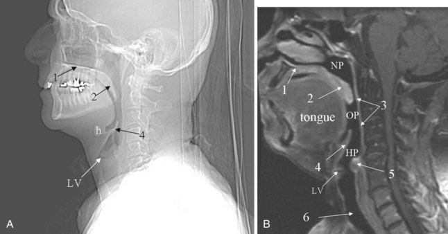
Sometimes visualized by a cervical spine radiographic study with soft tissue neck technique or on the CT scout view or the MR sagittal view of the neck is a transversely oriented, air-containing lucent stripe, located just below the base of the aryepiglottic folds, which indicates the position of the air-filled laryngeal ventricle (Fig. 2-16). This marks the position of the true vocal cords, which are just below this lucent stripe. Lateral to the aryepiglottic fold is the pyriform sinus of the pharynx. This anterior mucosal recess lies between the posterior third of the thyroid cartilage and the aryepiglottic fold. The extreme lower aspect of the pyriform sinus is situated between the mucosa-covered arytenoids and the mucosa-covered thyroid cartilage, at the level of the true vocal cords. The air column caudally represents the cervical trachea. On the AP view, the false and true vocal cords above and below the laryngeal ventricles may be identified, as well as the subglottic region and the trachea.
In the lower neck (C3 to C7), the prevertebral soft tissue shadow differs from that in the cervicocranium because of the presence of the beginning of the esophagus and the prevertebral fascial space, which are recognized on the lateral radiograph as a fat stripe. By standard anatomic description, the esophagus begins at the level of C4; however, in vivo, the esophageal ostium may normally be found as high as C3 or as low as C6 and varies with the phase of swallowing and the flexion and extension of the cervical spine.25 The prevertebral soft tissue thickness, the distance between the posterior pharyngeal air column and the anterior portion of the third or fourth vertebra, should not exceed one half to three quarters of the diameter of the vertebral body. In the opinion of Harris and Mirvis, only the measurement at C3 is valid, and it should not exceed 4 mm (Fig. 2-17).12
2 Classic Plain Film Diagnosis
a Acute Epiglottitis
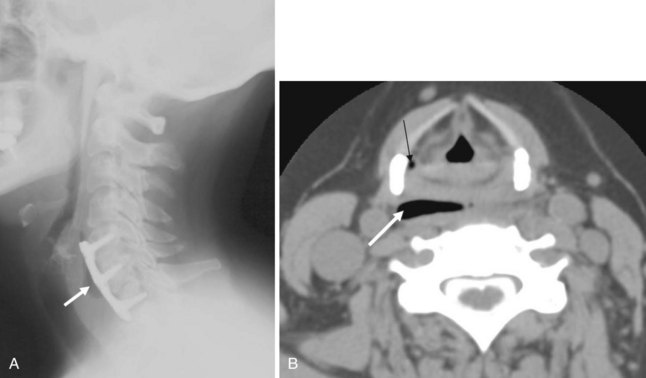
The findings on plain film are swelling or enlargement of the epiglottis. On the conventional lateral radiograph of the neck, thickening of the free edge of the epiglottis can be appreciated and is referred to as the “thumb sign” (Fig. 2-18). The width of the adult epiglottis should be less than one third of the AP width of the C4 body. Cross-sectional imaging is superfluous. However, the degree of airway compromise can theoretically be quantified by 3-D reformation.
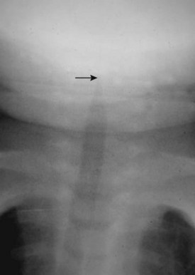
b Laryngotracheobronchitis or Croup
In laryngotracheobronchitis or croup, the subglottic larynx is involved. This condition affects younger children and has a less fulminant course than acute epiglottitis. The swelling of the soft tissues in the subglottic neck can be appreciated on an AP view of the neck (Fig. 2-19). There is usually a long segment narrowing of the glottis and subglottic airway with loss of the normal angle between the vocal cords and the subglottic airway. This has been referred to as the “steeple sign.” The hypopharynx is usually dilated because of the airway obstruction distally.
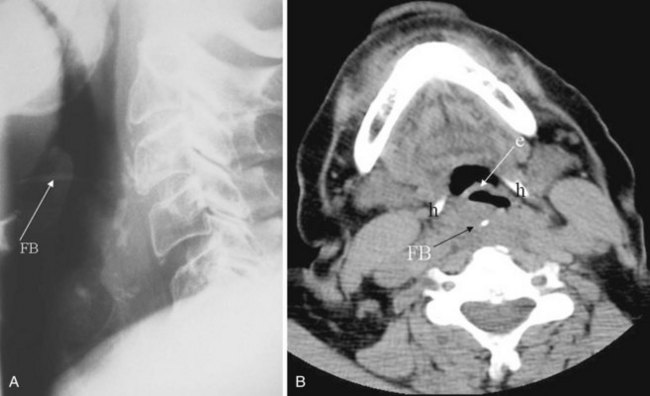
c Foreign Body
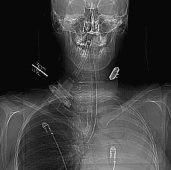
Plain films are usually obtained in the initial assessment of suspected foreign body ingestion. In children, up to 50% of witnessed foreign body ingestions are asymptomatic.26 Most foreign bodies are radiopaque, but wood and plastic usually are not visible on plain films. The radiopacity of ingested fishbone varies with the type of fish.27 In the neck, ingested foreign bodies most often lodge at the level of the pyriform sinus (Fig. 2-20).
C Chest Radiography
1 General Technique
Before the advent of CT, chest radiography was routinely ordered to assess pulmonary and cardiovascular status, and it is still a cost-efficient examination that yields a great deal of general information. The most common views of the chest are the posteroanterior (PA), anteroposterior (AP), and lateral projections (Fig. 2-21). The PA chest view is obtained with the patient’s anterior chest closest to the film cassette and the x-ray beam directed from a posterior to an anterior direction. Alternatively, the AP chest view is done with the patient’s back closest to the film cassette and the x-ray beam directed in the anterior to posterior direction. The part of the chest closest to the film cassette is the least magnified; therefore, the cardiac silhouette is larger on the AP projection. The lateral projection is most often performed with the patient’s left chest closest to the film cassette for better delineation of the structures in the left hemithorax, which is more obscured by the heart on a PA projection.
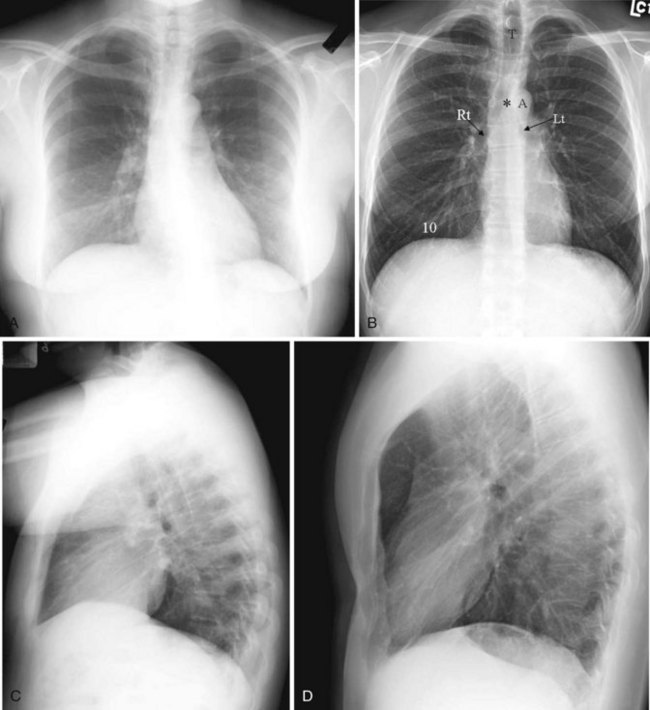
It is useful to train one’s eyes to analyze the chest radiograph systematically to cover the details of the chest wall, including the ribs, lungs (field and expansion), and mediastinal structures such as the heart and the outline of the tracheal-bronchial tree. On an adequate inspiratory film, the hemidiaphragms are below the anterior end of the sixth rib, or at least below the 10th posterior rib, and the lung expansion should be symmetrical. The right hemidiaphragm is usually half an interspace higher than the left, which is depressed by the heart (see Fig. 2-21A). Without doubt, the art of chest radiograph interpretation has diminished since the advent of CT, which demonstrates chest pathology with unparalleled clarity. However, chest radiography can still provide a composite survey of the chest at one quick glance. One can easily compare the lung volumes, identify the position of the mediastinum, determine the presence or absence of major airspace disease, and make a gross assessment of the cardiac status.
2 Interpretation of Pertinent Findings
a Level of Diaphragm
A high hemidiaphragm implies reduced lung volume, which can result from phrenic nerve paralysis, thoracic conditions causing chest pain that leads to splinting, or extrapulmonic processes such as an enlarged spleen or liver, pancreatitis, or subphrenic abscess. The presumed level of the hemidiaphragm is seen as an edge or transition between the aerated lungs and the opacity of the organs in the abdomen. If the thin leaves of the hemidiaphragm are outlined by air, a pneumoperitoneum should be considered (Fig. 2-22).
b Lung Aeration
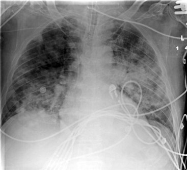
A well-expanded lung should appear radiographically lucent but be traversed by “lung markings,” thin threads of interstitium consisting of septa and arterial, venous, and lymphatic vessels. In most normal individuals, the lungs appear more lucent at the top owing to the distribution of the pulmonary vasculature, the effect of gravity, and overlying soft tissues such as breast tissues. In patients with congestive heart failure or pulmonary venous hypertension, this pattern is reversed, with “cephalization” and engorgement of the pulmonary veins in the upper lung zones (Fig. 2-23; also see Fig. 2-21D). In general, any process such as fluid, pus, or cells that replaces the airspaces of the lungs causes the x-ray beam to be more attenuated, allowing less of the beam to be transmitted through the patient to the film. This causes the affected areas to appear less dark or more opaque (white) on the film. A whole host of diseases could be responsible, depending on the clinical picture, including pleural effusion, pulmonary edema, pneumonia, lung mass, lung collapse or atelectasis, lung infarct or contusion, and metastatic disease (Fig. 2-24). The key from an anesthesiologist’s point of view is not to make the correct pathologic diagnosis but to note the abnormality, which may affect ventilation, and adjust the anesthetic practice accordingly.
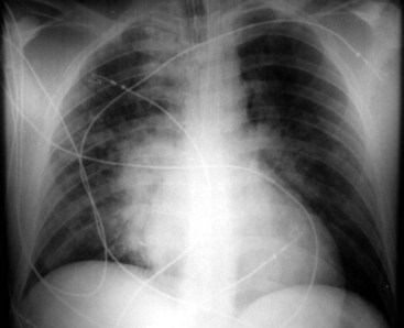
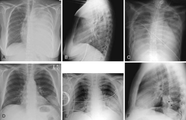
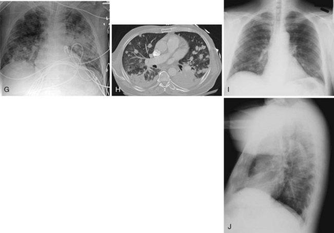
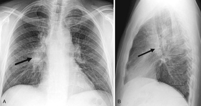
Figure 2-24 A and B, Left pleural effusion. Posteroanterior (PA) view of the chest (A) shows almost complete “white-out” of the left hemithorax and minimal residual aerated left upper lung zone. There is a mass effect with deviation of the trachea to the right. On the lateral view (B), the pleural effusion is less apparent. The tipoff is the lack of the expected lucency overlying the spine at the base (compare Fig. 2-21, C and D). C, Pulmonary edema. Anteroposterior (AP) view of the chest demonstrates bilateral hazy lung fields with air bronchogram. A tracheostomy tube is present. D through F, Left lower lung mass. Notice that although the inspiratory effort is the same on both the PA (D) and the AP (E) view (i.e., hemidiaphragm below ninth posterior rib), the cardiac silhouette and the left lower lobe mass appear larger on the AP view by virtue of the film geometry and magnification factor. The lateral view (F) helps to localize the disease process to the lateral segment of the left lower lobe. A mass is noted with postobstructive atelectasis (arrows). G and H, Aspergillosis. AP chest radiograph (G) shows nodular densities in both lungs. The differential diagnosis includes inflammatory and neoplastic processes. Notice that the tip of the endotracheal tube is in a good position, above the carina, and there is a central line on the right. Axial computed tomogram of the chest (H) better demonstrates the nodular pattern of lung involvement. I and J, Melanoma metastases to the lungs. The PA (I) and lateral (J) radiographs of the chest demonstrate nodular densities in both lungs in a patient with known melanoma. These examples show that radiographic findings are similar when the lung parenchyma is infiltrated with inflammatory or neoplastic cells.
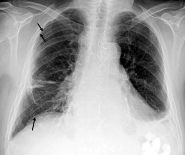
In contrast to the increased opacity of the lung caused by the preceding conditions is a hemithorax, which appears too lucent and devoid of the expected lung markings. Two entities should be considered. Foremost is a pneumothorax (Fig. 2-25); if the pneumothorax is large, the collapsed lung will be medially applied against the mediastinum. If the mediastinum is shifted away from the midline, a tension pneumothorax may be present, and emergent management is required. More often than not, the cause is the presence in patients with chronic obstructive pulmonary disease of large emphysematous blebs, which are sometimes difficult to differentiate from a moderate to large pneumothorax.
c Mediastinum and Heart
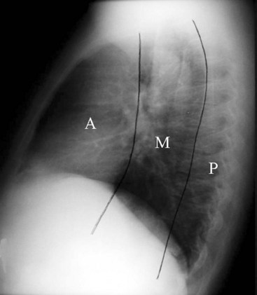
Felson proposed a radiologic approach to subdividing the mediastinum on a lateral radiograph into three compartments: anterior, middle, and posterior.28 The anterior and middle mediastinum are divided by an imaginary line that extends along the back of the heart and front of the trachea. The middle and posterior mediastinal compartments are separated by a similar line that connects a point on each thoracic vertebra about 1 cm behind its anterior margin (Fig. 2-26).28 Conditions that can be found in each of the compartments of the mediastinum are logically based on the anatomic structures found within the compartment. For example, tracheal, esophageal, and thyroid lesions would lie in the middle mediastinum. Neurogenic tumors and spinal problems would be in the posterior mediastinum. Cardiac and thymic lesions would occupy the anterior mediastinum. Certain diseases such as lymph node disorders, lymphoma, and aortic aneurysms may arise in any or all three compartments. Many modifications to the divisions of the mediastinum have been proposed.29
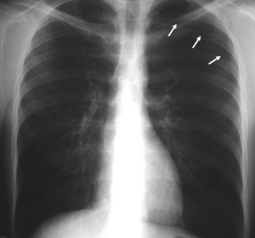
The great vessels and the heart should be centrally located on the AP view of the mediastinum. The aortic knob is usually on the left, and the cardiothoracic ratio on the AP view is roughly less than 50%. The hila are composed of the pulmonary arteries and their main branches, the upper lobe pulmonary veins, the major bronchi, and the lymph glands (Fig. 2-27).
d Tracheobronchial Tree
The positions of the trachea, carina, and main stem bronchi are outlined by air. The carinal bifurcation angle is typically 60 to 75 degrees.29 The right main stem bronchus has a steeper angle than the left (see Fig. 2-21); it usually branches off the trachea at an angle of 25 to 30 degrees, whereas the left main stem bronchus leaves the trachea at a 45- to 50-degree angle. The trachea is a tubular structure that extends from the cricoid cartilage to the carina, which is located approximately at the T5 level. C-shaped hyaline cartilage rings, which can calcify with age, outline the trachea anteriorly. The posterior trachea is membranous. The mean transverse diameter of the trachea is approximately 15 mm for women and 18 mm for men.29 The trachea in the cervical region is midline, but it is deviated to the right in the thorax.
Endotracheal Tube Positioning
Adequate positioning of an endotracheal tube (ETT) in an intubated patient is usually documented by obtaining a chest radiograph. The tip should be intrathoracic and at a distance above the carina that ensures equal ventilation to both lungs. One should evaluate the position of the ETT with the patient’s head and neck in a neutral position; however, this may not be possible in an intensive care unit setting. The tip of the ETT may move up or down by 1 to 2 cm with flexion or extension of the head. Rotation of the head and neck usually results in ascent of the tip.29 The optimal position of the tip of the ETT is 3 to 5 cm above the carina, to allow enough latitude in movement of the tube with turning of the patient’s head, and the inflated cuff should be below the vocal cords (Fig. 2-28).30 Malpositioning of the cuff at the level of the vocal cords or pharynx increases the risk of aspiration. Overinflation of the cuff at the level of the vocal cords may lead to necrosis.31 The inflated cuff of the ETT should fill the tracheal air column without changing its contour. Overall, the ETT size should be about two thirds of the diameter of the tracheal lumen. At times, the tip of the ETT extends beyond the carina, resulting in intubation of the right main bronchus, which can be detected by asymmetrical breath sounds or on chest radiographs. If this condition goes unrecognized, atelectasis in the underaerated lung may result (Fig. 2-29).
IV Cross-Sectional Anatomy and Pathology: Computed Tomography and Magnetic Resonance Imaging
A Midface
The major features of the face develop during the fourth to eighth week of gestation as a result of the growth, migration, and merging of a number of processes bordering on the stomodeum, which is a slitlike invagination of the ectoderm that marks the location of the mouth. At the fourth gestational week, one unpaired and two paired prominences, derivatives of the first branchial arch, can be identified bordering the stomodeum. The unpaired median frontonasal prominence is located superiorly, the paired maxillary processes are lateral, and the paired mandibular processes are inferior.32 The various cleft lip and palate and cleft face syndromes can be explained by the failure of these different processes to grow, migrate, and merge properly.32
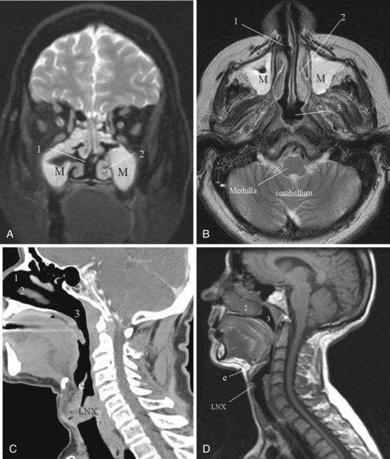
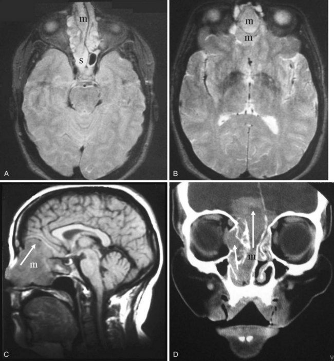
Relevant to anesthetic practice is an awareness that midline craniofacial dysraphism can be categorized into two groups: an inferior group, in which the clefting primarily affects the upper lip, with or without the nose, and a superior group, in which the clefting primarily affects the nose, with or without involvement of the forehead and the upper lip. It is the inferior group that is associated with basal encephalocele (i.e., sphenoidal, sphenoethmoid, and ethmoid encephaloceles), callosal agenesis, and optic nerve dysplasias. The superior group is characterized by hypertelorism, a broad nasal root, and a median cleft nose, with or without a median cleft upper lip. The superior group is also associated with an increased incidence of frontonasal and intraorbital encephaloceles (Fig. 2-30).32 The presence of these phenotypic features should alert the anesthesiologist to the possibility of an encephalocele intruding into the nasal cavity, and caution can then be exercised when inserting a nasogastric tube (NGT) or nasal airway.
B Nose and Nasal Cavity
The nose is pyramidal in shape and includes both the external apparatus and the nasal cavity. It is one of the two gateways to the aerodigestive tract. Most of the airflow to the lungs occurs through the nasal cavity. Mouth breathing is not physiologic; it is a learned action. The three physiologic functions of the nose are respiration, defense, and olfaction.33 In respiration, airflow is modified by nasal resistance at the level of the nares and the nasal valves to allow efficient pulmonary ventilation. A major portion of the nasal airflow passes through the middle meatus. The passage of inspired air through the nasal cavity allows humidification and warming.33
1 Imaging Anatomy Overview
Cross-sectional imaging of the nose and paranasal sinuses allows one to examine the air passage from the nares to the nasopharynx. A dedicated examination of the nose and sinuses yields detailed information about this region (Fig. 2-31). Incidental imaging of the sinuses and airway on a routine brain or spine study often allows general assessment of the airway that might be useful in the overall preoperative assessment of a patient (Fig. 2-32).
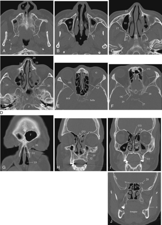
The bony housing of the nose and the nasal cavities is well depicted by CT. By changing the viewing windows and level, one can delineate the soft tissue component to better advantage. The nasal cavity is divided into two cavities separated by the nasal septum. The roof of the nasal cavity is formed by the cribriform plate of the ethmoid. The hard palate serves as the floor. Protruding into the nasal cavities along the lateral walls are mucosa-covered, scroll-like projections of bone called the inferior, middle, superior, and supreme turbinates or conchae. The supreme turbinates are seen in only 60% of people.33 The air space beneath and lateral to each turbinate, into which the paranasal sinuses drain, is referred to as the meatus.
In addition to clearly defining the anatomy, cross-sectional imaging can also be a window to viewing physiologic function, in particular the nasal cycle (the cyclic variation in the thickness of the mucosa of the nasal cavity), which repeats every 20 minutes to 6 hours.33,34 This physiologic change is manifested as alternating side-to-side swelling of the turbinates.
2 Pertinent Imaging Pathology
a Congenital and Developmental Abnormalities
Congenital Choanal Stenosis and Atresia
The development of the nasal cavity is complete by the second month of fetal life. From the second to the sixth month of prenatal life, the nostrils are closed by epithelial plugs that later recanalize to establish a patent nasal cavity. Failure of this process could account for the congenital stenoses and atresias that cause nasal airway obstruction and are often seen in conjunction with craniofacial anomalies.32
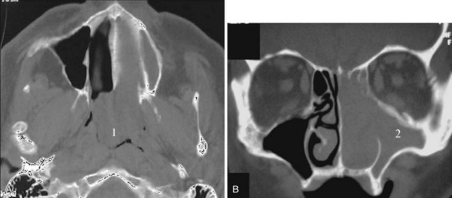
Congenital nasal airway obstruction most commonly occurs in the posterior nasal cavity secondary to choanal atresia (Fig. 2-33). The atresias may be bony, membranous, or both. At birth, severe respiratory difficulty and inability to insert an NGT more than 3 to 4 cm into the nose despite the presence of air in the trachea and lungs suggests the diagnosis of atresia. However, most atresias are unilateral, and may remain undetected until late in life.
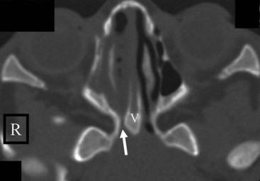
Stenosis of the posterior nasal cavity (choanae) is probably more common than true atresia. About 75% of children with bilateral choanal stenosis or atresia have other congenital abnormalities such as Apert’s syndrome, Treacher Collins syndrome, or fetal alcohol syndrome. Because the pathology is usually manifested as bony overgrowth, CT is the imaging modality of choice. The major feature of atresia is an abnormal widening of the vomer (Fig. 2-34). Nasal airway obstruction may also result from rhinitis or turbinate hypertrophy.
Deviated Septum
The cartilage of the nasal capsule, which is the foundation of the upper part of the face, eventually becomes ossified or atrophied with age. All that remains of the cartilage of the nasal capsule in adults is the anterior part of the nasal septum and the alar cartilages that surround the nostrils. The midline septal cartilage is continuous with the cartilaginous skull base. At birth, the lateral masses of the ethmoid are ossified, but the septal cartilage and the cribriform plates are still cartilaginous. Another ossification center appears in the septal cartilage anterior to the cranial base and becomes the perpendicular plate of the ethmoid. In about the third to sixth year of life, the lateral masses of the ethmoid and the perpendicular plate become united across the roof of the nasal cavity by ossification of the cribriform plate, which unites with the vomer below somewhat later. Growth of the septal cartilage continues for a short time after craniofacial union is complete, and this probably accounts for what is commonly seen as deviated nasal septum.32
Concha Bullosa
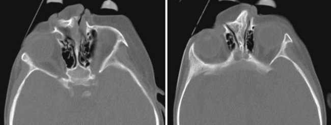
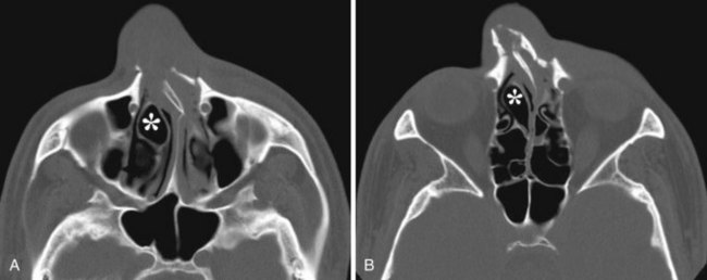
The term concha bullosa refers to an aerated turbinate, most often the middle turbinate, either unilateral or bilateral. In most cases it an incidental finding. However, it can be quite large and narrows the nasal air passage. Knowing which nasal cavity is narrowed by the presence of a concha bullosa helps guide the selection of which nasal cavity to cannulate (Fig. 2-35).
b Inflammatory Conditions
Polyposis
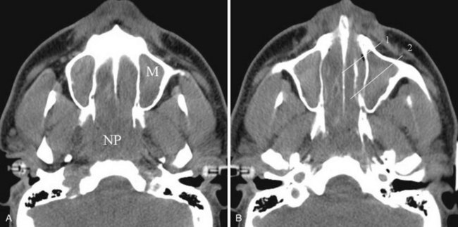
Nasal airway obstruction may result from rhinitis, polyposis, or turbinate hypertrophy. These entities affecting the airway are easily recognizable on cross-sectional imaging. Sensibly, the presence of polyposis may discourage an anesthesiologist from attempting nasal intubation (Figs. 2-36 and 2-37).
c Trauma
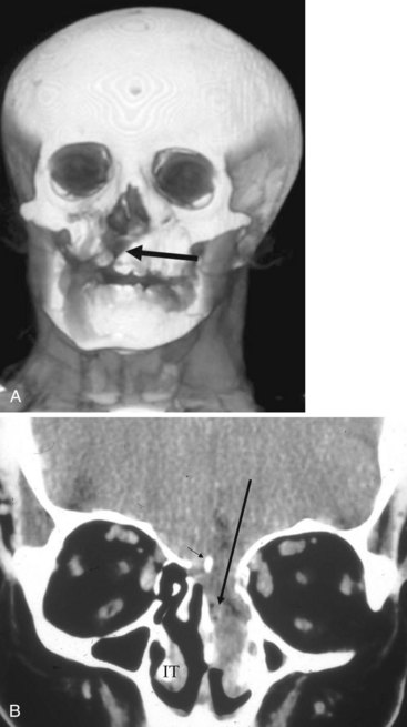
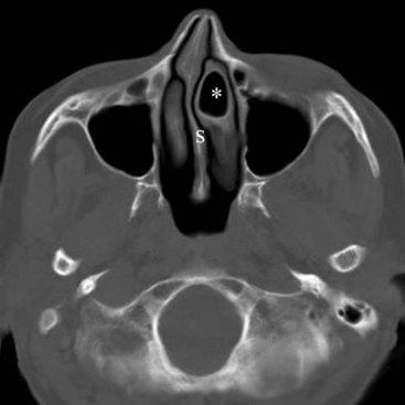
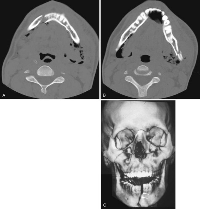
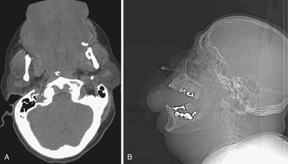
Facial fractures are often classified using the Le Fort system and its variants. This system is based on experiments predicting the course of fractures on the basis of lines of weakness in the facial skeleton. Nasal fractures are the most common facial fractures and may involve the nasal bones or the cartilaginous structures. If the nasal septum is fractured and a hematoma results, the vascular supply to the cartilage may be compromised, leading to cartilage necrosis. If the septal hematoma is not recognized and treated, it becomes an organized hematoma, which causes thickening of the septum and can result in impaired breathing (Fig. 2-38). Without doubt, CT is the modality of choice for evaluating trauma to the facial structures. Three-dimensional reconstruction and surface rendering can also be performed to better highlight fracture deformities. Even if all the details of a complex facial fracture are not known, an oral airway is preferable to a nasal airway, except in the case of mandibular fracture (Fig. 2-39), for which the nasal approach to intubation is preferred.
d Tumors and Other Conditions
Malignant Tumors
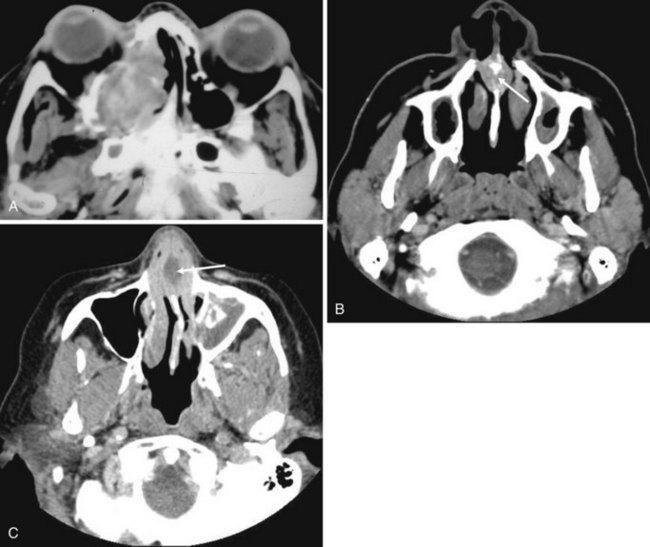
Malignant tumors of the nasal cavity and the paranasal sinuses are rare and have a poor prognosis because they are frequently diagnosed in an advanced stage. They are often accompanied by inflammatory disease. MRI is superior to CT in differentiating tumor from inflammatory disease and therefore is useful in delineating the tumor boundary from the often-associated inflammatory component. Inflammatory diseases involve a high water content; therefore, they have high T2-weighted intensity and appear bright on MRI. Nasal and paranasal tumors are usually cellular and have an intermediate-intensity signal on T2-weighted imaging (Fig. 2-40).35,36 CT is useful for assessing bone involvement. The histology of the tumor can sometimes be suggested by the way in which the bone is affected: aggressive bone destruction is usually seen in squamous cell carcinomas (SCCs), metastatic lung and breast cancers, a few sarcomas, and rare fibrous histiocytomas (Fig. 2-41).
Nonmalignant Destructive Tumors
Juvenile Nasopharyngeal Angiofibroma
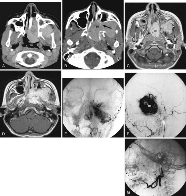
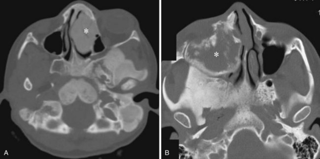
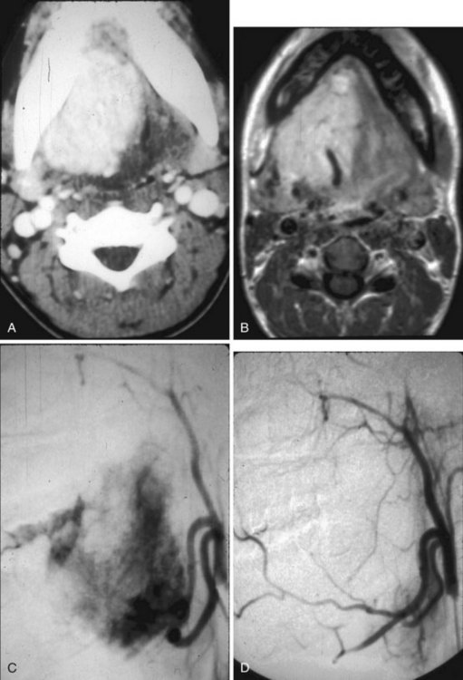
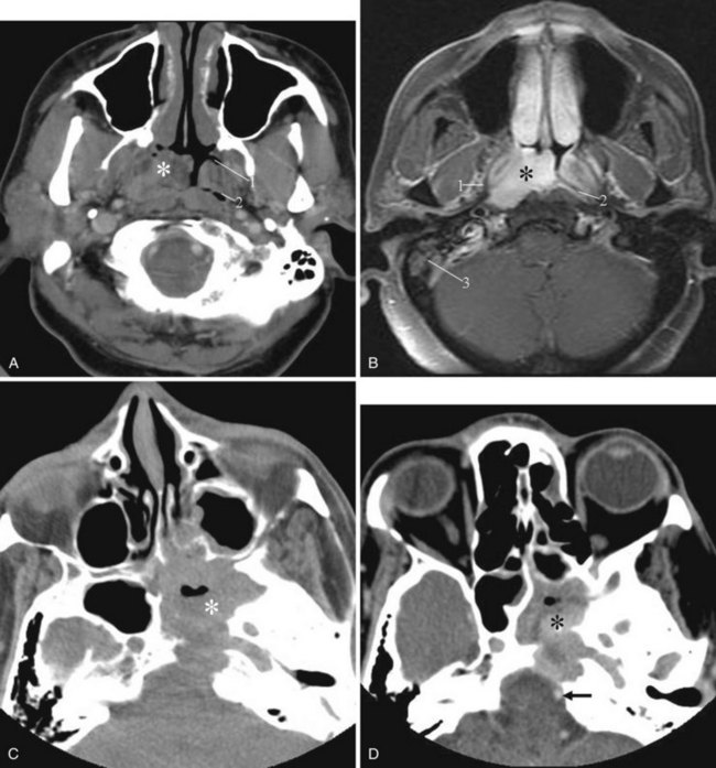
Juvenile nasopharyngeal angiofibroma is a benign hypervascular tumor found almost exclusively in young adolescent men. It is a nonmalignant, locally destructive tumor of the sinonasal cavity. The most common presenting signs are unilateral nasal obstruction and spontaneous epistaxis. The tumor usually arises at the sphenopalatine foramen at the lateral nasopharyngeal wall and is locally destructive over time.35 The imaging characteristics consist of a nasal cavity and nasopharyngeal mass, a widened pterygopalatine fossa, anterior displacement of the posterior wall of the maxillary sinus, and erosion of the medial pterygoid plate (Fig. 2-42). Treatment is surgical resection, often with preoperative embolization to decrease the blood supply.
Wegener’s Granulomatosis
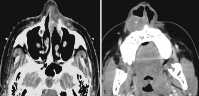
Wegener’s granulomatosis, a necrotizing vasculitis, usually affects the upper and lower respiratory tracts and causes a renal glomerulonephritis. It is probably autoimmune in origin. It most often involves the nasal septum first and may arise as a chronic nonspecific inflammatory process. This process becomes diffuse, and septal ulcerations and perforations occur. Secondary bacterial infection often complicates the clinical and imaging picture (Fig. 2-43).35
Fibrous Dysplasia
Fibrous dysplasia, an idiopathic bone disorder, is not a tumor but can encroach on the airway and sinuses. Most patients are young at the time of diagnosis. There are monostotic and polyostotic forms. Craniofacial bones are more often involved in the polyostotic form (Fig. 2-44).35
C Oral Cavity
The oral cavity, contiguous with the oropharynx, is the primary conduit to the gastrointestinal tract. The development of the mouth and that of the face are centered on a surface depression, the stomodeum, just below the developing brain. The ectoderm covering the forebrain extends into the stomodeum, where it lies adjacent to the foregut. The junctional zone between the ectoderm and the endoderm is the oropharyngeal membrane, which corresponds to Waldeyer’s ring. Dissolution of the oropharyngeal membrane in the fourth gestational week results in establishing patency between the mouth and the foregut.37
1 Imaging Anatomy Overview
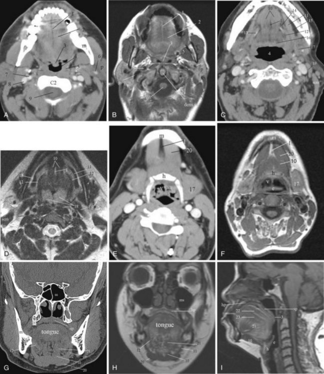
CT and MRI are used extensively for evaluation of the oral cavity. The advantages of CT are the speed of data acquisition and the ability to detect calcifications pertinent in the evaluation of inflammatory diseases affecting the salivary glands. For evaluating the extent of tumor infiltration of the soft tissues, MRI is superior to CT; however, it is easily degraded by motion artifacts (Fig. 2-45).
Motor innervation comes from the hypoglossal nerve, which courses between the mylohyoid and hyoglossus muscles. The sensory input from the anterior tongue is from the lingual nerve, which is a branch of the trigeminal nerve (CN V). Special sensory taste fibers from the anterior two thirds of the tongue course with the lingual nerve before forming the chorda tympani nerve, which subsequently joins the facial nerve (CN VII). The special sensory fibers from the posterior one third of the tongue (tongue base) are supplied by the glossopharyngeal nerve (CN IX). The arterial blood supply to the tongue is from branches of the lingual artery, which itself is a branch of the external carotid artery. Venous drainage is to the internal jugular vein.25,38
Several named spaces and regions in the oral cavity are mentioned in brief because of their anatomic importance with respect to the structures contained within them. The sublingual region is below the mucosa of the floor of the mouth, superomedial to the mylohyoid muscle and lateral to the genioglossus-geniohyoid muscles. It is primarily fat filled and is continuous with the submandibular region at the posterior margin of the mylohyoid muscle. The contents of this space include the sublingual gland and ducts, the submandibular gland duct (Wharton’s duct) and sometimes a portion of the hilum of the submandibular gland, anterior fibers of the hyoglossus muscle, and the lingual artery and vein. The hyoglossus muscle is an important surgical landmark (see Fig. 2-45C). Lateral to this muscle, one can identify Wharton’s duct, the hypoglossal nerve, and the lingual nerve; the lingual artery and vein lie medially. Wharton’s duct runs anteriorly from the gland, traveling with the hypoglossal nerve and the lingual nerve (mandibular branch of the trigeminal nerve). Initially, it lies between the hyoglossus muscle and the mylohyoid muscle. More anteriorly, it lies between the genioglossus and mylohyoid muscles. The duct drains into the floor of the mouth, just lateral to the frenulum of the tongue.39
The submandibular space or fossa is defined as the space inferior to the mylohyoid muscle, between the mandible and the hyoid bone. At the posterior margin of the mylohyoid muscle, the submandibular space is continuous with the sublingual space and the anterior aspect of the parapharyngeal space. This communication allows the spread of pathology. The submandibular space is primarily fat filled and contains the superficial portion of the submandibular gland and lymph nodes, lymphatic vessels, and blood vessels. The anterior bellies of the digastric muscle lie in the paramedian location in this space. Branches of the facial artery and vein course lateral to the anterior digastric muscle in the fat surrounding the submandibular gland. The artery lies deep to the gland, and the anterior facial vein is superficial.38 One important anatomic point is that pathology intrinsic to the submandibular gland displaces the facial vein laterally. Other masses lateral to the gland, including nodes, can be identified with the vein interposed between the gland and the mass.40
The lips are composed of orbicularis muscle, which comprises muscle fibers from multiple facial muscles that insert into the lips and additional fibers proper to the lips. The innervation to the lips is from branches of the facial nerve (CN VII). The vestibule of the mouth, or the gingivobuccal region, is the potential space separating the lips and cheeks from the gums and teeth. The parotid gland ducts and mucous gland ducts of the lips and cheek drain into this space, which is contiguous posteriorly with the oral cavity through the space between the last molar tooth and the ramus of the mandible.38
2 Pertinent Imaging Pathology
a Macroglossia
The tongue makes up the bulk of soft tissues in the oral cavity. Enlargement of the tongue, which is defined clinically as protrusion of the tongue beyond the teeth or alveolar ridge in the resting position, compromises the oral airway and makes the insertion of airway devices challenging. Larsson and colleagues defined the appearance of macroglossia on CT imaging as (1) base of the tongue more than 50 mm in the transverse dimension, (2) genioglossus muscle more than 11 mm in the transverse dimension, (3) midline cleft on the tongue surface, and (4) submandibular glands normal in size but bulging out of the platysma muscle owing to tongue enlargement.41
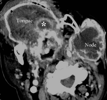
There are congenital and noncongenital causes of macroglossia. The congenital syndromes in which macroglossia can be seen are trisomy 21, Beckwith-Wiedemann syndrome, hypothyroidism, and mucopolysaccharidoses. The more common noncongenital causes are tumor of the tongue, lymphangioma, hemangioma, acromegaly, and amyloid (Figs. 2-46 and 2-47). Rarely, infection can result in macroglossia, especially in an immune-compromised host (Fig. 2-48).
b Micrognathia and Retrognathia
Micrognathia is a term used to describe an abnormally small mandible. Retrognathia is defined as abnormal posterior placement of the mandible. These two findings often coexist. Abnormal growth or placement of the mandible can be caused by malformation, deformation, or connective tissue dysplasia.42 The most familiar syndromic form featuring an abnormal mandible is in the Pierre Robin sequence. Other clinical entities include the Treacher Collins, Stickler, and DiGeorge syndromes. Thin-section CT with 2-D or 3-D reformation provides information regarding the size and proportions of the maxilla, nose, mandible, and airway. Micrognathia and retrognathia not only contribute to airway obstruction but also are possible indicators of difficult direct laryngoscopy and endotracheal intubation that can lead to life-threatening complications (Figs. 2-49 and 2-50).42
c Exostosis
Hyperostosis of the hard palate or mandible is a benign disease that is usually of no clinical significance. Most often these are small exostoses. They may arise from the oral surface of the hard palate (torus palatinus), from the alveolar portion of the maxilla in the molar region along the lingual surface of the dental arch (torus maxillaris), or along the lingual surface of the mandible (torus mandibularis) (Fig. 2-51). Large lesions may restrict tongue motion and distort the airway, leading to speech disturbance.
d Tumors
Only 7% of oral cavity lesions are malignant; however, most of these malignant tumors are SCCs. Other neoplasms include minor salivary gland tumors, lymphomas, and sarcomas. Risk factors for SCC of the oral cavity include a long history of tobacco and alcohol use. SCC can arise anywhere in the oral cavity, but it has a predilection for the floor of the mouth, the ventrolateral tongue, and the soft palate complex including the retromolar trigone area and the anterior tonsillar pillar. Most lesions are moderately advanced at the time of presentation; 30% to 65% of patients with SCC of the oral cavity have nodal involvement at the time of diagnosis. The tumors of the oral cavity are usually less aggressive than SCCs arising from the oropharynx. Both CT and MRI are useful for assessing tumor extent and nodal involvement.39
D Pharynx
The pharynx is a mucosa-lined tubular structure and is the portion of the aerodigestive tract extending from the skull base to the cervical esophagus. By convention and for ease of discussion, it is divided into three parts: nasopharynx, oropharynx, and hypopharynx. Anatomically, the nasopharynx is defined as extending from the skull base to the hard palate, the oropharynx from the hard palate to the hyoid bone, and the hypopharynx from the hyoid bone to the caudal margin of the cricoid cartilage. Below the level of the cricoid cartilage, the cervical esophagus begins. The hypopharynx can be further subdivided into the pyriform sinus region, the posterior wall, the postcricoid region, and the lateral surface of the aryepiglottic folds.25,38
The arterial supply to the pharynx is from branches of the external carotid artery, including the ascending pharyngeal artery, tonsillar branches of the facial artery, and the palatine branches of the maxillary artery. Superior and inferior thyroid arteries supply most of the lower pharynx. The primary venous drainage is through the superior and inferior thyroid veins and the pharyngeal veins into the internal jugular veins. The lymphatic drainage is complex and extensive to the jugular, retropharyngeal, posterior cervical, and paratracheal nodes.25,43,44
Imaging studies of the pharynx most commonly include plain radiographic films, barium studies, CT, and MRI. In contrast to CT and MRI, a barium study is a dynamic imaging technique that can demonstrate the sequential contractions of the pharyngeal musculature during deglutition. It can show whether the pharyngeal wall is fixed or pliable and may detect mucosal lesions not apparent on CT or MRI. CT and MRI are most commonly done with the patient in the supine position and the neck in the neutral position. Intravenous contrast is recommended with CT for evaluation of lymphadenopathy. The inherent differences in signal intensity between tumor, fat, and muscle on MRI often allow accurate delineation of the tumor extent without gadolinium, which is the contrast agent commonly used in clinical practice.44 Because of the clinical concern for perineural spread of tumor in the head and neck region, MRI is usually performed with contrast.
1 Nasopharynx
a Imaging Anatomy Overview
The nasopharynx is an air-containing cavity that occupies the uppermost extent of the aerodigestive tract. The roof and posterior wall of the nasopharynx are formed by the sphenoid sinus, the clivus, and anterior aspect of the first two cervical vertebrae. The inferior aspect of the nasopharynx is formed by the hard palate, the soft palate, and the ridge of pharyngeal musculature that opposes the soft palate when it is elevated (Passavant’s ridge). The lateral nasopharyngeal walls are formed by the margins of the superior constrictor muscle. Anteriorly, the nasopharynx is in direct continuity with the nasal cavity through the posterior choanae. The nasopharynx is in direct communication with the middle ear cavity through the eustachian tubes (Fig. 2-52).44
b Pertinent Imaging Pathology
Adenoidal Hypertrophy
The adenoids are lymphatic tissues that are located in the upper posterior aspect of the nasopharynx. Prominent adenoids are typical in children; by the age of 2 to 3 years, the adenoids can fill the entire nasopharynx and extend posteriorly into the posterior choanae. Regression of the lymphoid tissue starts during adolescence and continues into later life. By the age of 30 to 40 years, adenoidal tissue is minimal, although normal adenoidal tissue may occasionally be seen in adults in the fourth and fifth decades of life. Adenoid tissues appear isodense to muscle on CT imaging (see Fig. 2-52D). On MRI, the adenoids are isointense to muscle on T1-weighted imaging and hyperintense on T2-weighted imaging. If prominent adenoidal tissue is seen in an adult, human immunodeficiency virus (HIV) infection should be suspected.44 Differentiation between lymphomatous involvement and hypertrophy of the adenoids is not possible on imaging, because both entities are hyperintense on T2-weighted imaging. Enlargement of the adenoids can cause partial obstruction of the nasopharyngeal airway and make insertion of an NGT difficult. They may also contribute to the symptom complex of obstructive sleep apnea.
Infection and Abscess
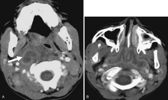
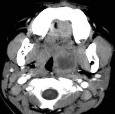
Abscess in the parapharyngeal space may result from tonsillar infection or from iatrogenic or traumatic perforation of the pharynx. The infection may extend from the skull base to the submandibular region and can be difficult to differentiate from a neoplastic process. If large enough, it may compromise the airway. Infection spreading to retropharyngeal nodes (suppurative adenitis) can also obliterate the nasopharynx airway (Fig. 2-53).
Tumors and Other Conditions
SCC of the nasopharynx is a relatively rare cancer that accounts for only 0.25% of all malignancies in North America. It has a high rate of incidence in Asia, however, where it is the most common tumor in men, accounting for 18% of cancers in China.43 SCC accounts for 70% or more of the malignancies arising in the nasopharynx, and lymphomas account for about 20%. The remaining 10% are a variety of lesions, including adenocarcinoma, adenoid cystic carcinoma, rhabdomyosarcoma, melanoma, extramedullary plasmacytoma, fibrosarcoma, and carcinosarcoma. Risk factors for SCC in the nasopharynx include the presence of immunoglobulin A antibodies against Epstein-Barr virus, human leukocyte antigens HLA-A2 and HLA-B-Sin histocompatibility loci, nitrosamines, polycyclic hydrocarbons, poor living conditions, and chronic sinonasal infections.44 The most common presentation is nodal disease. There is no correlation between primary tumor size and the presence of nodal disease. Imaging with CT and MRI is performed to map accurately the extent of the disease, not for histologic diagnosis (Fig. 2-54).
2 Oropharynx
a Imaging Anatomy Overview
The arterial supply to the oropharynx is mainly from branches of the external carotid artery: the tonsillar branch of the facial artery, the ascending pharyngeal artery, the dorsal lingual arteries, and the internal maxillary and facial arteries. The venous drainage is primarily through the peritonsillar veins, which pierce the constrictor musculature and drain into the common facial vein and the pharyngeal plexus. Lymphatic drainage is mainly to the jugulodigastric chain from the skull base to the cricoid cartilage, the retropharyngeal nodes, the posterior triangle nodes from the level of the skull base to the cricoid cartilage, and sometimes the parotid nodes.44
b Pertinent Imaging Pathology
Tonsillar Hypertrophy
During the third and fourth fetal months, lymphoid tissues invade the pharyngeal region of the adenoid tonsils, the palatine region (palatine tonsils), and the root of the tongue (lingual tonsils).37 The adenoids are located in the roof of the nasopharynx. As mentioned previously, enlargement of the palatine and lingual tonsils may compromise the airway (Fig. 2-55).
Tonsillitis and Peritonsillar Abscess
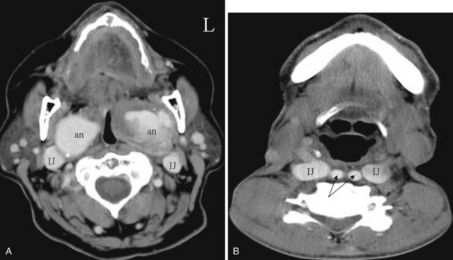
Acute bacterial tonsillitis is most commonly caused by β-hemolytic streptococcus, staphylococcus, pneumococcus, or Haemophilus species. It is usually a self-limited disease; however, uncontrolled infection of the tonsils may result in a peritonsillar abscess or, rarely, a tonsillar abscess. On CT imaging, the findings of acute or chronic tonsillitis are nonspecific. Focal homogeneous swelling of the palatine tonsils can be present and is difficult to differentiate from tumor. The imaging features of abscess formation are a low-density center and an enhancing rim of soft tissue (Fig. 2-56). Peritonsillar abscess is the accumulation of pus around the tonsils. The infection may extend to the retropharyngeal, parapharyngeal, or submandibular spaces.
Tortuous Internal or Common Carotid Artery
If the course of either the common carotid artery or the internal carotid artery is directed medially, bulging of the submucosa of the oropharynx or hypopharynx may result. In this less protected location, the artery is more vulnerable to trauma. Imaging is useful to prevent unnecessary biopsy of this pseudosubmucosal mass (Fig. 2-57).
Tumors and Other Conditions
SCC is the most common neoplasm of the oropharynx, and its predisposing factors include alcohol and tobacco use. Most recently, epidemiologic and molecular data have shown a strong association between human papillomavirus (HPV) infection—in particular, exposure to or infection with high-risk HPV-16—and the development of oropharyngeal cancer, especially tonsillar cancer. This subset of patients with oropharyngeal cancers present at a younger age and have distinct molecular and pathologic differences, with an as yet unexplained improved prognosis.45 There is also a proven causal relationship between HPV-16 and the development of cervical cancer, and for this reason HPV infection is considered a sexually transmitted disease.
The site of origin determines the spread of the tumor; the most common locations are the anterior and posterior tonsillar pillars, tonsillar fossa, soft palate, and base of the tongue (Fig. 2-58). Staging of tumor in the oropharynx depends on the size of the tumor and whether it has invaded adjacent structures. Other neoplasms include lymphoma, minor salivary gland tumors, and mesenchymal tumors.
3 Hypopharynx
The boundary of the hypopharynx is classically defined as the segment of the pharynx that extends from the level of the hyoid bone and the valleculae to the cricopharyngeus or the lower level of the cricoid cartilage. By definition, the cervical esophagus starts at the caudal end of the cricoid cartilage. The cricopharyngeus muscle acts as the superior esophageal sphincter. It arises from the lower aspect of the inferior constrictor muscle attached to the cricoid. The upper esophageal sphincter is normally closed until a specific volume and pressure in the hypopharynx trigger relaxation of the cricopharyngeus muscle to allow a bolus of food to pass into the cervical esophagus. The cricopharyngeus muscle then closes to prevent reflux.43
a Imaging Anatomy Overview
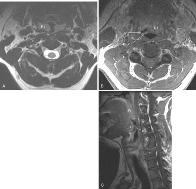
The hypopharynx can be divided into four regions: the pyriform sinuses, the posterior wall of the hypopharynx, the postcricoid region, and the lateral surface of the aryepiglottic folds. The pyriform sinus is the anterolateral recess of the hypopharynx. The anterior pyriform sinus mucosa abuts on the posterior paraglottic space. The most caudal portion of the pyriform sinus lies at the level of the true vocal cords. The lateral aspect of the aryepiglottic folds forms the medial wall of the pyriform sinus (Fig. 2-59). This is considered a marginal zone because the aryepiglottic folds are part of both the hypopharynx and the supraglottic larynx. Tumors involving the medial surface of the aryepiglottic folds behave like laryngeal tumors. The biologic behavior of tumors arising from the lateral surface of the aryepiglottic folds is similar to that of the more aggressive pharyngeal tumors. The lateral wall of the pyriform sinus is formed by the thyroid membrane and cartilage.44
b Pertinent Imaging Pathology
Zenker’s Diverticulum
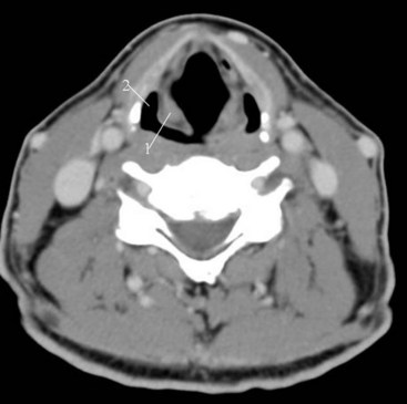
It is postulated that dyssynergy of the cricopharyngeus muscle plays a role in the formation of this pulsion diverticulum of the hypopharynx. The diverticulum typically extends posteriorly and laterally, usually to the left, and may appear as an incidental, air-filled structure in the hypopharynx on CT and MRI. If alerted to the presence of a diverticulum, one should take more caution during blind advancement of an NGT, which may take an errant course (Fig. 2-60).
Tumors and Other Conditions
Squamous Cell Carcinoma
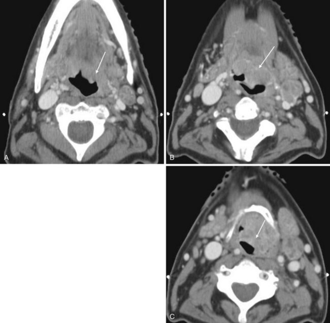
The hypopharynx is lined by stratified squamous epithelium, and most tumors of the hypopharynx are SCCs (Fig. 2-61). The risk factors for SCC of the hypopharynx include alcohol abuse, smoking, and previous radiation therapy. Patients with Plummer-Vinson syndrome have a higher incidence of postcricoid carcinoma. Extensive submucosal growth is common and can be appreciated only on imaging. The airway may be effaced and displaced. Most patients have metastases to the cervical nodes at presentation. Between 4% and 15% of patients with SCC of the hypopharynx have a synchronous or metachronous second primary tumor.44,46
E Larynx
1 Imaging Anatomy Overview
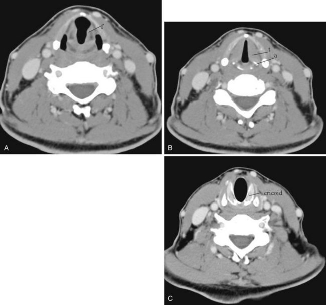
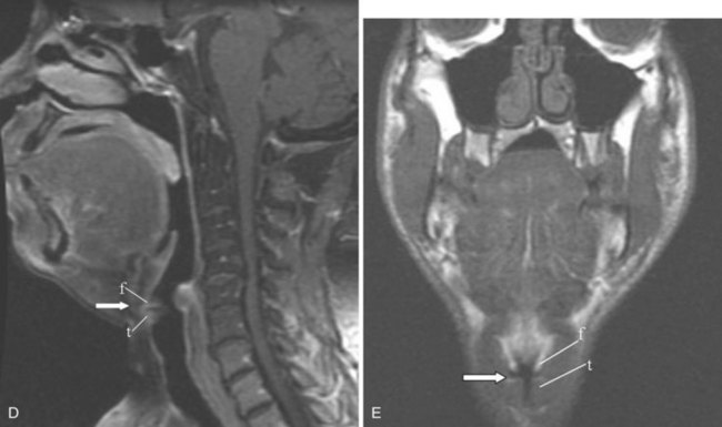
Before the advent of CT and MRI, examination of the larynx consisted of plain radiographic films, multidirectional tomography, barium swallow, and laryngography. On a sagittal view, one can easily identify the hyoid bone, epiglottis, aryepiglottic folds, and vestibule, which is the space extending from the epiglottis to the level of the false vocal cords. At the level of the thyroid cartilage, a tiny slit of air is seen directed in the anterior-posterior direction. This is the laryngeal ventricle, which separates the false vocal cords from the true vocal cords (see Fig. 2-15).
Barium swallow, which is still used today, provides dynamic information about the swallowing mechanism and any dysfunction or incoordination of the muscles of swallowing and respiration. CT and MRI allow visualization of structures deep to the mucosa (Fig. 2-62); however, breathing and swallowing movements make imaging of the larynx difficult. The faster CT scanning technology available today allows the entire neck to be scanned in a single breath-hold. Helical technology allows reformation of the airway in multiple planes with one acquisition. MRI examination of the larynx continues to be problematic because of motion artifacts intrinsic and extrinsic to the larynx and longer acquisition time compared with CT. The advantage of MRI over CT is its ability to distinguish greater soft tissue contrast. The multiplanar capability of both CT and MRI is helpful in the evaluation of the mucosal folds and spaces in the neck.
In brief, the larynx can be considered as a conduit to the lungs. It also provides airway protection against aspiration and allows vocalization. It has an outer supporting skeleton comprising a series of cartilages, fibrous sheets, muscles, and ligaments that provides structure and protection for the inner mucosal tube, the endolarynx. Between the cartilages and the mucosal surface lie the paraglottic and pre-epiglottic spaces, which contain loose areolar tissues, lymphatics, and muscles. Superiorly, the larynx is suspended from the hyoid bone, which is attached to the styloid process at the base of the skull by the stylohyoid ligament. Calcification of the stylohyoid ligament (see Fig. 2-11) has been proposed as a cause of difficult intubation.18 Contraction of the muscles attached to the hyoid bone move it anterior and superior with consequent similar movements of the larynx. This sequence of movements also pulls the epiglottis to the horizontal plane, eventually inverting and closing the glottis and contributing to protection from aspiration.47,48
The parts of the exoskeleton of the larynx that are visible on plain radiography include the arytenoid cartilage, the cricoid cartilage, and the thyroid cartilage, which is the largest cartilage of the larynx. The thyroid cartilage is made up of two shieldlike laminae that fuse anteriorly to form the laryngeal prominence (Adam’s apple). The angle of the fusion is usually more acute and more prominent in men. Paired superior and inferior cornua project from the posterior margin of the thyroid cartilage. The superior thyroid cornu is connected with the dorsal tip of the greater cornu of the hyoid bone by the thyrohyoid membrane. The inferior cornu articulates medially with the lateral wall of the cricoid cartilage to form the cricothyroid joint, where the thyroid cartilage rocks back and forth. Radiographically, this is an important landmark; it marks the entry of the recurrent laryngeal nerve to the larynx.38 Muscles that attach to the external surface of the thyroid cartilage include the sternothyroid and thyrohyoid muscles and the inferior pharyngeal constrictors. The thyrohyoid membrane bridges the gap between the upper surface of the thyroid cartilage and the hyoid bone. Likewise, the cricothyroid membrane spans the distance between the lower margin of the thyroid cartilage and the cricoid cartilage.47
The cricoid cartilage, which is shaped like a signet ring with the larger part facing posteriorly, is the base of the larynx. On the upper surface of the cricoid lamina are two paired articular facets, on which are situated the arytenoid cartilages. The arytenoid cartilages are important surgical and imaging landmarks.25 Each cartilage is pyramidal in shape. The base is formed by two projections: the muscular process situated on the posterolateral margin and the vocal process located anteriorly. The muscular and vocal processes are at the level of the true vocal cords.
The corniculate cartilage sits at the apex of the pyramid and is located above the level of the laryngeal ventricle, at the level of the false vocal cords. The arytenoid cartilages are important in maintaining airway patency and participate in vocalization by altering the opening of the glottis and the tension of the vocal cords. This is achieved by movements between the arytenoid and cricoid cartilages: adduction, abduction, anterior-posterior sliding, and medial-lateral sliding.25
For surgical planning purposes, the endolarynx can be divided into three compartments: the supraglottic larynx, the glottic larynx (glottis), and the subglottic larynx. The supraglottic airway can be defined as extending from the tip of the epiglottis to the laryngeal ventricles; it includes the false vocal cords, epiglottis, aryepiglottic folds, and arytenoids. The glottis is defined by the mucosal coverings of the true vocal cords and the anterior and posterior commissures. The subglottic larynx includes the undersurface of the true vocal cords and extends to the lower border of the cricoid cartilage.38,47 The laryngeal ventricle demarcates two embryologically distinct laryngeal components: the supraglottic larynx and the subglottic larynx. The supraglottic larynx forms from primitive anlage and has richer lymphatics compared with the tracheobronchial buds. This embryologic and histologic difference accounts for the higher incidence of nodal metastasis at presentation of squamous cell cancer of the supraglottic larynx as compared to that of the glottic or subglottic primary.47
Several structures in the endoskeleton of the larynx are worth describing. The epiglottis is a yellow elastic fibrocartilage; its tip defines the cephalad margin of the supraglottic larynx. It has a flattened teardrop or leaf shape that tapers to an inferior point called the petiole of the epiglottis, where it attaches to the thyroid cartilage through the thyroepiglottic ligament. The superior and lateral edges are free. Most of the epiglottis extends behind the thyroid cartilage; the tip may be above the hyoid bone and sometimes can be seen through the oral cavity. It is held in place and stabilized by the hyoepiglottic and thyroepiglottic ligaments. The hyoepiglottic ligament is a tough, fibrous, fanlike ligament that extends from the ventral midline of the epiglottis to the dorsal margin of the hyoid cartilage. Immediately above the ligament are the pharyngeal recesses, the valleculae, which are situated just caudal to the tongue base. The epiglottis helps to guard against aspiration; during swallowing, the aryepiglottic folds pull the sides of the epiglottis down, thereby narrowing the entrance to the larynx.25,48
The quadrangular membrane stretches anteriorly from the upper arytenoid and corniculate cartilages to the lateral margin of the epiglottis and contributes to the support of the epiglottis.47 The superior free margin of this membrane forms the support for the aryepiglottic fold, which stretches from the upper margin of the arytenoids to the lateral margin of the epiglottis. The corniculate and cuneiform cartilages within the aryepiglottic fold help support the edge of each fold. These small, mucosa-covered cartilages are visualized on laryngoscopy as two small protuberances at the posterolateral border of the rima glottidis.25 The aryepiglottic folds form the lateral margin of the vestibule of the supraglottic airway. The upper part of the aryepiglottic fold is the aryepiglottic muscle, which functions like a purse string to close the opening of the larynx during swallowing. Lateral to the aryepiglottic folds are the pyriform sinuses. The apex, the most inferior aspect of the pyriform sinus, is at the level of the true vocal cords.
The inferior free margin of the quadrangular membrane forms the ventricular ligament, which extends anteriorly from the superior arytenoid cartilage to the inner lamina of the thyroid cartilage and supports the free edge of the false vocal cords. The false vocal cords are superior to the true vocal cords and are separated by a lateral pouching of the airway, the laryngeal ventricle.47 A second set of ligaments, the vocal ligaments, lies parallel and inferior to the ventricular ligament. It also extends from the vocal process of the arytenoid cartilage to the inner lamina of the thyroid just above the anterior commissure. The vocal ligament provides medial support for the true vocal cords. The space between the left and right vocal cords is referred to as the rima glottis, through which air passes to allow breathing and vocalization. Extending from the vocal ligament is another fibrous membrane, the conus elasticus, which attaches inferiorly to the upper inner margin of the cricoid cartilage. The conus spans part of the gap between the thyroid and cricoid cartilages.25,47
The muscles of the larynx are categorized as intrinsic and extrinsic muscles. The intrinsic muscles regulate the aperture of the rima glottis: (1) the thyroarytenoid makes up the bulk of the true vocal cord and has a lateral and a medial belly; (2) the lateral cricoarytenoids extend from the muscular process of the arytenoid cartilage to the upper lateral cricoid cartilage and function to adduct the cords; (3) the posterior cricoarytenoids extend from the muscular process of the arytenoid cartilage to the posterior surface of the cricoid cartilage and abduct the cords laterally; and (4) the intra-arytenoid muscle stretches from one arytenoid to the other and functions to adduct the vocal cords.25,47 The extrinsic muscle is the cricothyroid muscle, which extends from the lower thyroid cartilage anteriorly to the upper cricoid cartilage. The contraction of this muscle pivots the thyroid cartilage forward around an axis through the cricothyroid joint, which stretches and tenses the vocal cords, thus affecting pitch in vocalization.25,47
Because the vocal cords are not static structures, they are difficult to image. During normal respiration, the vocal cords are slightly abducted. During deep inspiration, the true vocal cords fully abduct against the lateral wall of the glottic airway. The airway opening becomes narrowed with medialization of the true cords during breath-holding with or without a Valsalva maneuver, expiration, and phonation. Extending below the true vocal cords to the cricoid cartilage is the infraglottic cavity. The trachea begins below the level of the cricoid cartilage.47
The larynx is innervated primarily by branches of the vagus nerve.25 The recurrent laryngeal nerve innervates all the intrinsic muscles of the larynx. If vocal cord paralysis is present and nerve damage is suspected, imaging should be tailored to follow the course of the recurrent laryngeal nerve in the neck and upper chest. The vagus nerve, after exiting the jugular foramen, passes vertically down the neck within the carotid sheath, between the internal jugular vein and the internal carotid artery (which becomes the common carotid artery) to the root of the neck. In front of the right subclavian artery, the recurrent laryngeal nerve branches from the vagus nerve, loops around the right subclavian artery, and ascends to the side of the trachea behind the common carotid artery, in the tracheoesophageal groove. On the left side, the recurrent laryngeal nerve arises at the level of the aortic arch. It loops around the arch at the point where ligamentum arteriosum is attached and ascends to the side of the trachea in the tracheoesophageal groove. The recurrent laryngeal nerve enters the larynx behind the cricothyroid joint and innervates all the muscles of the larynx except the cricothyroid muscle, which is an extrinsic muscle of the anterior larynx that is innervated by the external laryngeal branch of the superior laryngeal nerve, a branch of the vagus nerve in the neck. Sensory input from the laryngeal mucosa is by the internal laryngeal branch of the superior laryngeal nerve, which perforates the posterior lateral portion of the thyrohyoid membrane.25
The blood supply to the larynx is from two branches of the external carotid artery: the superior and inferior laryngeal arteries. The superior laryngeal artery, a branch of the superior thyroid artery, travels with the internal branch of the superior laryngeal nerve. The inferior laryngeal artery, a branch of the inferior thyroid artery, which is a branch of the thyrocervical trunk, accompanies the recurrent laryngeal nerve into the larynx.25
2 Pertinent Imaging Pathology
a Trauma
Fracture of the larynx, which usually occurs as a result of a vehicular accident, can involve the thyroid cartilage, the cricoid cartilage, or both. Laryngotracheal separation is usually fatal. Dislocation of the arytenoids relative to the cricoid cartilage may be encountered. Malalignment of the thyroid and cricoid cartilages results in dislocation of the cricothyroid joint. On imaging, the presence of air in the paraglottic soft tissues is an indication of laryngeal trauma (Fig. 2-63).
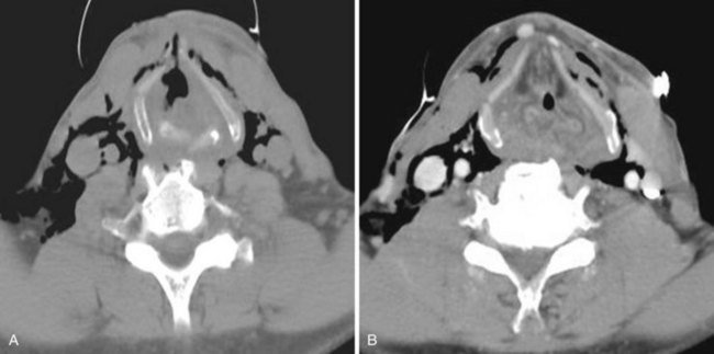
b Vocal Cord Paralysis
Vocal cord paralysis may be characterized as either a superior laryngeal nerve deficit, a recurrent laryngeal nerve deficit, or a total vagus nerve deficit. The entire course of the vagus nerve and the recurrent laryngeal nerve should be imaged when assessing vocal cord paralysis (Fig. 2-64).
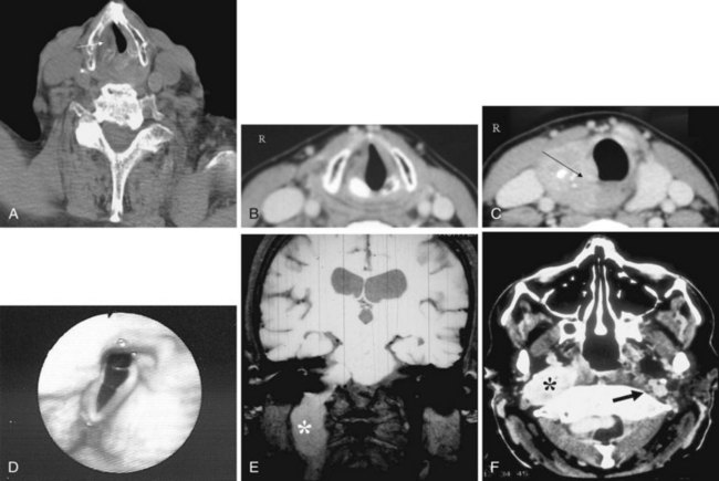
More commonly, vocal cord paralysis is caused by recurrent laryngeal nerve pathology. All of the laryngeal muscles, except for the cricothyroid muscle, are innervated by this nerve. Most findings are secondary to atrophy of the thyroarytenoid muscle, the muscle that contributes to the bulk of the true vocal cords. The vocal cords become thinner and more pointed. Compensatory enlargement of the ventricle and the pyriform sinus is seen.47 In the more acute phase, the paralyzed cord appears flaccid, prolapses medially because of the lack of muscular tone in the thyroarytenoid muscle, and demonstrates a lack of movement during breathing maneuvers and phonation.
c Congenital Lesions
The respiratory system is formed from an outpouching of the primitive pharynx.42,47 A tracheoesophageal septum is formed and separates the trachea from the primitive foregut. The laryngeal lumen is initially occluded and later recanalizes. Congenital lesions are related to delays in the development and maturation of the respiratory system.42,47
Laryngomalacia
Laryngomalacia represents a delay in the development of the laryngeal support system. The structures of the larynx are present but are not mature enough to keep the larynx open. Primarily, the supraglottic larynx is affected to a varying degree. The presentation in the infant may vary from a floppy epiglottis only to collapse of the entire supraglottic larynx on inspiration. This abnormality is self-limited, and the problem resolves with maturation.42,47
Webs and Atresias
Webs can be seen at any level of the larynx, but they are usually at the level of the true vocal cords. Subglottic webs are sometimes associated with cricoid abnormalities. Atresia of the larynx results from incomplete recanalization. Although the trachea is formed, there is no air passage to it.42,47
Stenosis
The most common cause of stenosis is prolonged tracheal intubation or tracheostomy. Typically, the pattern of involvement starts anteriorly and laterally before eventually circumferentially involving the membranous portion. Trauma-related stenosis has a more variable pattern. Ingestion of caustic material usually results in strictures along the posterior supraglottic airway and larynx.42,47 Both plain radiographic studies and CT are good at assessing the extent and length of the stenotic segment.
d Tumors and other Conditions
Benign Tumors
Benign masses encountered in the larynx include vocal cord nodules, juvenile papillomatosis, and other nonepithelial tumors such as hemangiomas, lipomas, leiomyomas, rhabdomyomas, chondromas, neural tumors, paragangliomas, schwannomas, and granular cell tumors.42
Cysts and Laryngoceles
Mucus-retention cysts can occur along any mucosal surface, but they are most common in the supraglottic larynx. Laryngoceles may be internal, external, or both. The common finding in a supraglottic mass is its connection with the laryngeal ventricle (Fig. 2-65).42,47
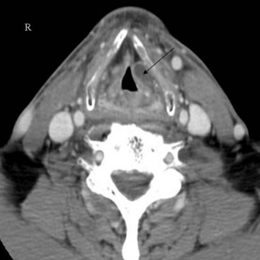
Malignant Neoplasms
Most laryngeal tumors are malignant, and SCC is the most common type. These cancers arise on the mucosal surface and can be readily visualized by direct endoscopy. Imaging with CT and MRI is used to define the extent of the disease. Cross-sectional imaging is useful to assess the degree and direction of airway compromise (Fig. 2-66). Other cell types found are adenocarcinoma, verrucous carcinoma, and anaplastic carcinoma. More rare tumors are sarcoma, melanoma, lymphoma, leukemia, plasmacytoma, fibrous histiocytoma, and metastatic disease.47
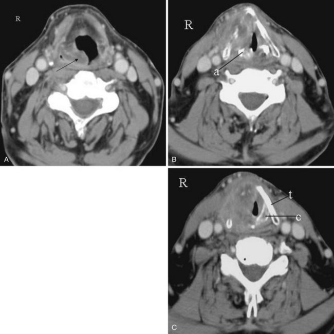
F Trachea
The trachea is a tubular structure that extends from the cricoid cartilage, at approximately the C6 level, to the carina, usually at the T5 or T6 level. It is a conduit between the larynx and the lungs and is composed of 16 to 20 incomplete hyaline cartilaginous rings bound in a tight elastic connective tissue that is oriented longitudinally. The cartilage forms about two thirds of the circumference of the trachea; the posterior border is formed by a fibromuscular membrane. The trachea is approximately 10 to 13 cm long (average length, 11 cm). The diameter of the tracheal lumen depends on the height, age, and gender of the subject. In men, the tracheal diameter ranges from 13 to 25 mm in the coronal imaging plane and from 13 to 27 mm in the sagittal imaging plane. In women, the dimensions are 10 to 21 mm in the coronal plane and 10 to 23 mm in the sagittal plane.49,50 Cross-sectional area correlates best with height in children.
The axial sections of the tracheal lumen assume the following successive shapes: round, lunate, flattened, and elliptical. The luminal shape is also affected by the respiratory cycle, maneuvers, and body position. During rapid and deep inspiration, the thoracic portion of the trachea widens and the cervical portion narrows; the opposite occurs with expiration. The innervation of the trachea is from the parasympathetic tracheal branches of the vagus nerve, the recurrent laryngeal nerve, and the sympathetic nerves. The trachea has a segmental blood supply from multiple branches of the inferior thyroidal arteries and bronchial arteries.25
2 Pertinent Imaging Pathology
Early detection of tracheal pathology is unusual because significant compromise of the airway can be present before symptoms manifest. More than 75% occlusion of the luminal diameter at rest, and more than 50% occlusion during exertion, must be present before symptoms of airway obstruction are manifested.50 If symptoms are present, a superior mediastinal mass is often found on PA chest radiography. Also, the tracheal air column may be deviated or narrowed. Rarely, tracheal enlargement occurs as a result of tracheomalacia in patients with cystic fibrosis or Ehlers-Danlos complex. Pathology affecting the trachea can largely be classified as extrinsic or intrinsic diseases.
a Extrinsic Tracheal Pathology
Thyroid Goiter
One of the more common extrinsic pathologies affecting the cervical and substernal trachea is a goiter of the thyroid gland. The trachea is usually displaced laterally, and luminal compression is evident. Vocal cord paralysis, hoarseness, dyspnea, and dysphagia may be the presenting symptoms. These symptoms are all predictable and are predicated on the location of the goiter with respect to the trachea, the esophagus, and the recurrent laryngeal nerve. The lateral and posterior extension of abnormal soft tissue with respect to the larynx displaces the airway anteriorly and laterally and may be a cause of difficult intubation (Fig. 2-67).
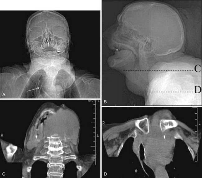
Thyroid Carcinoma and Nodes
As in the case of thyroid goiter, any mass involving or enlarging the thyroid gland can result in airway displacement and compression (Fig. 2-68). Enlarged lymph nodes secondary to lymphoma or metastatic disease can also cause extrinsic compression of the trachea.
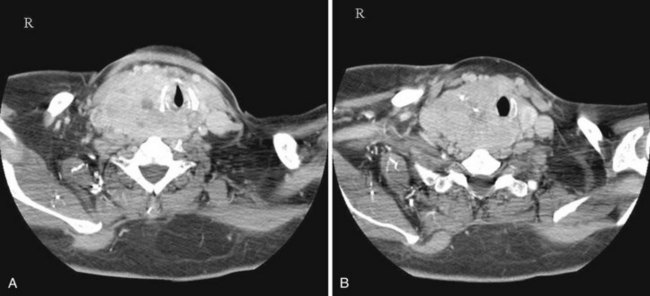
b Intrinsic Tracheal Pathology
Iatrogenic Injury
A late complication of translaryngeal intubation is stenosis at the cuff site, tip, or stoma site of the tracheostomy. Cuff trauma is related to pressure necrosis, in which the cuff pressure exceeds the capillary pressure. The incidence of this complication has decreased significantly since the introduction of the high-volume, low-pressure cuff, which is more pliable and can mold to the contours of the trachea. The blood supply to the anterior cartilages is susceptible to pressure effects, and anterior tracheal scarring may occur. With increased pressure, the posterior membranous part of the trachea can become affected, and the scarring becomes more circumferential. This type of injury is related to the position of the cuff and is seen radiographically as smooth tapering over one or two cartilage segments. Symptoms may arise from 2 weeks to months after extubation. Less common long-term complications of endotracheal intubation include tracheomalacia and tracheoesophageal fistula (TEF).13,51
c Non-Neoplastic Tracheal Narrowing
The intrinsic pathology of diffuse tracheal narrowing results from trauma due to aspiration of heat or of caustic or acid chemicals, radiation therapy, or intubation injury; additional unusual causes include sarcoidosis, Wegener’s granulomatosis, fungal infection, croup, and congenital conditions (Fig. 2-69).
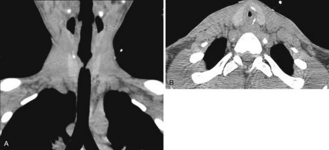
Tracheoesophageal Fistula
TEF is a common congenital anomaly, with an incidence of 1 in 3000 to 4000 births. TEF is often associated with esophageal atresia.50 There are several forms of TEF. The most common is a proximal esophageal atresia with a distal TEF. This anomaly may be associated with severe neonatal respiratory distress and may necessitate emergent tracheostomy. It is not uncommon for more than one fistula to be present, and there may be other associated anomalies affecting the cardiovascular, gastrointestinal, renal, or central nervous system (Fig. 2-70).
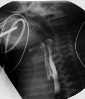
d Tumors and Other Conditions
Primary malignant neoplasms of the trachea are uncommon; laryngeal and bronchial primary tumors are much more common. In adults, however, primary neoplasms of the trachea are more common than benign tumors. The most common malignant tumor is SCC.50
The trachea may be secondarily involved by metastatic disease, either from a remote primary tumor or by direct invasion, such as from a thyroid primary (Fig. 2-71).
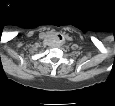
VI Clinical Pearls
• In children and in adults during flexion, the anterior atlantodental interval (AADI) is normally about 5 mm. In adults, it is generally accepted that the AADI is 3 mm or less.
• Although the majority of head extension occurs at the atlanto-occipital joint, some extension can also occur at C1-C2. In patients with limited or no extension possible at the atlanto-occipital joint, general extension of the head actually brings the larynx “anterior,” thereby limiting the visibility of the larynx on laryngoscopy.
• A nonunited terminal dental ossification center (os terminale) may be mistaken for a fracture of the odontoid tip.
• Conditions that are associated with odontoid hypoplasia are the Morquio, Klippel-Feil, and Down syndromes; neurofibromatosis; dwarfism; spondyloepiphyseal dysplasia; osteogenesis imperfecta; and congenital scoliosis. Patients with these conditions are predisposed to atlantoaxial subluxation and craniocervical instability, and hyperextension of the head for intubation should be avoided.
• Counterclockwise rotation of the larynx should be suspected if the frontal view of the cervical spine demonstrates a deviated tracheal air column.
• In addition to partial or total choanal atresia, nasal airway obstruction may result from rhinitis or from turbinate hypertrophy.
• In a patient with radiation-induced changes to the neck, the increased rigidity of the soft tissues should be taken into account during laryngoscopy for endotracheal intubation and in selecting the correct size of a laryngeal mask airway (LMA). Specifically, the LMA needs to be one or even two sizes smaller than predicted by the patient’s weight.
All references can be found online at expertconsult.com.
10 Streitwieser DR, Knopp R, Wales LR, et al. Accuracy of standard radiographic views in detecting cervical spine fractures. Ann Emerg Med. 1983;12:538–542.
12 Harris JH, Mirvis SE. The radiology of acute cervical spine trauma, ed 3. Baltimore: Williams & Wilkins; 1996.
13 Crosby ET, Lui A. The adult cervical spine: Implications for airway management. Can J Anaesth. 1990;37:77–93.
15 Nichol HC, Zuck D. Difficult laryngoscopy: The “anterior” larynx and the atlanto-occipital gap. Br J Anaesth. 1983;55:141–144.
19 Keenan MA, Stiles CM, Kaufman RL. Acquired laryngeal deviation associated with cervical spine disease in erosive polyarticular arthritis: Use of the fiberoptic bronchoscope in rheumatoid disease. Anesthesiology. 1983;58:441–449.
20 White A, Kander PL. Anatomical factors in difficult direct laryngoscopy. Br J Anaesth. 1975;47:468–474.
21 Chou HC, Wu TL. Mandibulohyoid distance in difficult laryngoscopy. Br J Anaesth. 1993;71:335–339.
22 Frerk CM, Till CB, Bradley AJ. Difficult intubation: Thyromental distance and the atlanto-occipital gap. Anaesthesia. 1996;51:738–740.
30 Goodman LR, Putnam CE. Intensive care radiology: Imaging of the critically ill. Philadelphia: WB Saunders; 1983.
31 Bishop MJ, Weymuller EA, Jr., Fink BR. Laryngeal effects of prolonged intubation. Anesth Analg. 1984;63:335–342.
1 Curry TS, III., Dowdey JE, Murry RC. Radiation. In: Curry TS, III., Dowdey JE, Murry RC. Christensen’s physics of diagnostic radiology. ed 4. Philadelphia: Lea & Febiger; 1990:1–9.
2 Curry TS, III., Dowdey JE, Murry RC. Production of x rays. In: Curry TS, III., Dowdey JE, Murry RC. Christensen’s physics of diagnostic radiology. ed 4. Philadelphia: Lea & Febiger; 1990:10–35.
3 Curry TS, III., Dowdey JE, Murry RC. Attenuation. In: Curry TS, III., Dowdey JE, Murry RC. Christensen’s physics of diagnostic radiology. ed 4. Philadelphia: Lea & Febiger; 1990:70–86.
4 Curry TS, III., Dowdey JE, Murry RC. Basic interactions between x-rays and matter. In: Curry TS, III., Dowdey JE, Murry RC. Christensen’s physics of diagnostic radiology. ed 4. Philadelphia: Lea & Febiger; 1990:61–69.
5 Curry TS, III., Dowdey JE, Murry RC. Physical characteristics of x-ray film and film processing. In: Curry TS, III., Dowdey JE, Murry RC. Christensen’s physics of diagnostic radiology. ed 4. Philadelphia: Lea & Febiger; 1990:137–147.
6 Curry TS, III., Dowdey JE, Murry RC. Computed tomography. In: Curry TS, III., Dowdey JE, Murry RC. Christensen’s physics of diagnostic radiology. ed 4. Philadelphia: Lea & Febiger; 1990:289–322.
7 Hounsfield GN. Computerized transverse axial scanning (tomography): 1. Description of system. Br J Radiol. 1973;46:1016–1022.
8 Hamberg LM, Rhea JT, Hunter GJ, Thrall JH. Multi-detector row CT: Radiation dose characteristics. Radiology. 2003;226:762–772.
9 Curry TS, III., Dowdey JE, Murry RC. Nuclear magnetic resonance. In: Curry TS, III., Dowdey JE, Murry RC. Christensen’s physics of diagnostic radiology. ed 4. Philadelphia: Lea & Febiger; 1990:432–469.
10 Streitwieser DR, Knopp R, Wales LR, et al. Accuracy of standard radiographic views in detecting cervical spine fractures. Ann Emerg Med. 1983;12:538–542.
11 Miller MD, Gehweiler JA, Martinez S, et al. Significant new observations on cervical spine trauma. AJR Am J Roentgenol. 1978;130:659–663.
12 Harris JH, Mirvis SE. The radiology of acute cervical spine trauma, ed 3. Baltimore: Williams & Wilkins; 1996.
13 Crosby ET, Lui A. The adult cervical spine: Implications for airway management. Can J Anaesth. 1990;37:77–93.
14 Cattell HS, Filtzer DL. Pseudosubluxation and other normal variations in the cervical spine in children: A study of one hundred and sixty children. J Bone Joint Surg Am. 1965;47:1295–1309.
15 Nichol HC, Zuck D. Difficult laryngoscopy: The “anterior” larynx and the atlanto-occipital gap. Br J Anaesth. 1983;55:141–144.
16 Manaligod JM, Bauman NM, Menezes AH, Smith RJ. Cervical vertebral anomalies in patients with anomalies of the head and neck. Ann Otol Rhinol Laryngol. 1999;108:925–933.
17 Bougaki M, Sawamura S, Matsushita F, Hanaoka K. Difficult intubation due to ossification of the anterior longitudinal ligament. Anaesthesia. 2004;59:303–304.
18 Sharwood-Smith GH. Difficulty in intubation: Calcified stylohyoid ligament. Anaesthesia. 1976;31:508–510.
19 Keenan MA, Stiles CM, Kaufman RL. Acquired laryngeal deviation associated with cervical spine disease in erosive polyarticular arthritis: Use of the fiberoptic bronchoscope in rheumatoid disease. Anesthesiology. 1983;58:441–449.
20 White A, Kander PL. Anatomical factors in difficult direct laryngoscopy. Br J Anaesth. 1975;47:468–474.
21 Chou HC, Wu TL. Mandibulohyoid distance in difficult laryngoscopy. Br J Anaesth. 1993;71:335–339.
22 Frerk CM, Till CB, Bradley AJ. Difficult intubation: Thyromental distance and the atlanto-occipital gap. Anaesthesia. 1996;51:738–740.
23 Noback G. The developmental topography of the larynx, trachea and lungs in the fetus, newborn, infant and child. Am J Dis Child. 1923;26:515–533.
24 Wilson TG. Some observations on the anatomy of the infantile larynx. Acta Otolaryngol. 1953;43:95–99.
25 Standring S, ed. Gray’s anatomy, ed 40, Philadelphia: Elsevier, 2008.
26 Arana A, Hauser B, Hachimi-Idrissi S, Vandenplas Y. Management of ingested foreign bodies in childhood and review of the literature. Eur J Pediatr. 2001;160:468–472.
27 Carr A. Radiology of fish bone foreign bodies in the neck. J Laryngol Otol. 1987;101:407–408.
28 Felson B. The mediastinum. In: Felson B, ed. Chest roentgenology. Philadelphia: WB Saunders; 1973:389–420.
29 Guiterrez F. Thoracic imaging: A practical approach. New York: McGraw-Hill; 1999.
30 Goodman LR, Putnam CE. Intensive care radiology: Imaging of the critically ill. Philadelphia: WB Saunders; 1983.
31 Bishop MJ, Weymuller EA, Jr., Fink BR. Laryngeal effects of prolonged intubation. Anesth Analg. 1984;63:335–342.
32 Naidich TP, Blaser SI, Bauer BS, et al. Embryology and congenital lesions of the midface. In: Som PM, Curtin HD. Head and neck imaging. ed 4. St. Louis: Mosby; 2003:3–87.
33 Som PM, Shugar JMA, Brandwein MS. Anatomy and physiology. In: Som PM, Curtin HD. Head and neck imaging. ed 4. St. Louis: Mosby; 2003:87–147.
34 Mafee MF. Nasal cavity and paranasal sinuses. Mafee MF, Valvassori GI, Minerva B. Valvassori’s imaging of the head and neck, ed 2, New York: Thieme, 2004.
35 Som PM, Brandwein MS. Tumors and tumor-like conditions. In: Som PM, Curtin HD. Head and neck imaging. ed 4. St. Louis: Mosby; 2003:261–373.
36 Som PM, Shapiro MD, Biller HF, et al. Sinonasal tumors and inflammatory tissues: Differentiation with MR imaging. Radiology. 1988;167:803–808.
37 Som PM, Smoker RK, Balboni A, et al. Embryology and anatomy of the neck. In: Som PM, Curtin HD. Head and neck imaging. ed 4. St. Louis: Mosby; 2003:1757–1804.
38 Harnsberger R, Glastonbury CM, Michel MA, Koch B. Diagnostic imaging: Head and neck, ed 2. Salt Lake City, UT: Amirsys; 2011.
39 Smoker WRK. The oral cavity. In: Som PM, Curtin HD. Head and neck imaging. ed 4. St. Louis: Mosby; 2003:1377–1464.
40 Weissman JL, Carrau RL. Anterior facial vein and submandibular gland together: Predicting the histology of submandibular masses with CT or MR imaging. Radiology. 1998;208:441–446.
41 Larsson SG, Benson L, Westermark P. Computed tomography of the tongue in primary amyloidosis. J Comput Assist Tomogr. 1986;10:836–840.
42 Robson CD, Hudgins P. Pediatric airway disease. In: Som PM, Curtin HD. Head and neck imaging. ed 4. St. Louis: Mosby; 2003:1521–1594.
43 Million RR, Cassisi NJ, Mancuso AA. Hypopharynx: Pharyngeal walls, pyriform sinus, postcricoid pharynx. In: Million RR, ed. Management of head and neck cancer: A multidisciplinary approach. Philadelphia: Lippincott; 1994:505–532.
44 Mukherji S. Pharynx. In: Som PM, Curtin HD. Head and neck imaging. ed 4. St. Louis: Mosby; 2003:1465–1520.
45 Gillison ML, Koch WM, Capone RB, et al. Evidence for a causal association between human papillomavirus and a subset of head and neck cancers. J Natl Cancer Inst. 2000;92:709–720.
46 Strigenz MA, Toohill RJ, Grossman TW. Association of laryngeal and pulmonary malignancies: A continuing challenge. Ann Otol Rhinol Laryngol. 1987;96:621–624.
47 Curtin H. The larynx. In: Som PM, Curtin HD. Head and neck imaging. ed 4. St. Louis: Mosby; 2003:1595–1699.
48 Goldsmith T. Videofluoroscopic evaluation of oropharyngeal swallowing. In: Som PM, Curtin HD. s: Head and neck imaging. ed 4. St. Louis: Mosby; 2003:1727–1754.
49 Naidich DP, Webb R, Muller NL. Airways. In: Naidich DP, Zerhouni EA, Siegelman SS. Computed tomography and magnetic resonance imaging of the thorax. ed 3. Philadelphia: Lippincott-Raven; 1999:161–291.
50 Sasson JP, Abderlrahman NG, Aquino S, et al. Trachea: Anatomy and pathology. In: Som PM, Curtin HD. Head and neck imaging. ed 4. St. Louis: Mosby; 2003:1700–1726.
51 Calder I, Calder J, Crockard HA. Difficult direct laryngoscopy in patients with cervical spine disease. Anaesthesia. 1995;50:756–763.