Additional equipment used in anaesthesia and intensive care
Continuous positive airway pressure (CPAP)
Components
1. A flow generator producing high flows of gas (Fig. 13.1), or a large reservoir bag may be needed.
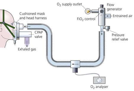
Fig. 13.1 A CPAP breathing system set-up.
2. Connecting tubing from the flow generator to the inspiratory port of the mask. An oxygen analyser is fitted along the tubing to determine the inspired oxygen concentration.
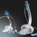
3. A tight-fitting mask or a hood. The mask or hood has both inspiratory and expiratory ports. A CPAP valve is fitted to the expiratory port.
4. If the patient is intubated and spontaneously breathing, a T-piece with a CPAP valve fitted to the expiratory limb can be used.
Mechanism of action
1. Positive pressure within the lungs (and breathing system) is maintained throughout the whole of the breathing cycle.
2. The patient’s peak inspiratory flow rate can be met.
3. The level of CPAP varies depending on the patient’s requirements. It is usually 5–15 cm H2O.
4. CPAP is useful in weaning patients off ventilators especially when positive end expiratory pressure (PEEP) is used. It is also useful in improving oxygentaion in type 1 respiratory failure, where CO2 elemination is not a problem.
5. Two levels of airway pressure support can be provided using inspiratory positive airway pressure (IPAP) and expiratory positive airway pressure (EPAP). IPAP is the pressure set to support the patient during inspiration. EPAP is the pressure set for the period of expiration This is commonly used in reference to bilevel positive airway pressure (BiPAP©). Using this mode, the airway pressure during inspiration is independent from expiratory airway pressure. This mode is useful in managing patients with type 2 respiratory failure as the work of breathing is reduced with improvements in tidal volume and CO2 removal.
Problems in practice and safety features
1. CPAP has cardiovascular effects similar to PEEP but to a lesser extent. Although the arterial oxygenation may be improved, the cardiac output can be reduced. This may reduce the oxygen delivery to the tissues.
3. A loose-fitting mask allows leakage of gas and loss of pressure.
4. A nasogastric tube is inserted in patients with depressed consciousness level to prevent gastric distension.
5. Skin erosion caused by the tight-fitting mask. This is minimized by the use of soft silicone masks or protective dressings or by using a CPAP hood. Rhinorrhoea and nasal dryness can also occur.
6. Nasal masks are better tolerated but mouth breathing reduces the effects of CPAP.
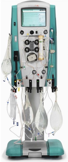
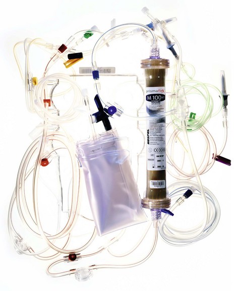
Haemofiltration
The widespread use of haemofiltration has revolutionized the management of critically ill patients with acute renal failure within the intensive therapy environment (Fig. 13.2). Haemofiltration is popular because of its relative ease of use and higher tolerability in the cardiovascularly unstable patient.
In the critical care setting, haemofiltration can be delivered by:
1. Continuous low flow therapy, which is typically run 24 h per day for more than 1 day, but may be stopped for procedures and filter or circuit changes. Continuous treatments are said to offer better cardiovascular stability and more efficient solute removal because of the steady biochemical correction and gradual fluid removal. Continuous therapy is also better suited to the frequently changing fluid balance situation in patients with multiorgan dysfunction in critical care.
2. Intermittent high flow systems, often 4-hour sessions with a new filter and circuit for each session.
Components
1. Intravascular access lines. These can either be arteriovenous lines (such as femoral artery and vein or brachial artery and femoral vein) or venovenous lines (such as the femoral vein or the subclavian vein using a single double-lumen catheter). The extracorporeal circuit is connected to the intravascular lines. The lines should be as short as possible to minimize resistance.
2. Filter or membrane (Fig. 13.3). Synthetic membranes are ideal for this process. They are made of polyacrylonitrile (PAN), polysulphone or polymethyl methacrylate. They have a large pore size to allow efficient diffusion (in contrast to the smaller size of dialysis filters).
3. Two roller pumps, one on each side of the circuit. Each pump peristaltically propels about 10 mL of blood per revolution and is positioned slightly below the level of the patient’s heart.
4. The collection vessel for the ultrafiltrate is positioned below the level of the pump.
Mechanism of action
1. At its most basic form, the haemofiltration system consists of a circuit linking an artery to a vein with a filter positioned between the two.
2. The patient’s blood pressure provides the hydrostatic pressure necessary for ultrafiltration of the plasma. This technique is suitable for fluid-overloaded patients who have a stable, normal blood pressure.
3. Blood pressure of less than a mean of 60 or 70 mmHg reduces the flow and the volume of filtrate and leads to clotting despite heparin.
4. In the venovenous system, a pump is added making the cannulation of a large artery unnecessary (Fig. 13.4). The speed of the blood pump controls the maintenance of the transmembrane pressure. The risk of clotting is also reduced. This is the most common method used. Blood flows of 30–750 mL/min can be achieved, although flow rates of 150–300 mL/min are generally used. This gives an ultrafiltration rate of 25–40 mL/min.
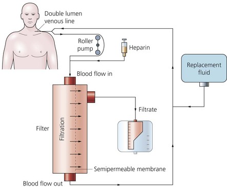
5. The fluid balance is maintained by the simultaneous reinfusion of a sterile crystalloid fluid. The fluid contains most of the plasma electrolytes present in their normal values (sodium, potassium, calcium, magnesium, chloride, lactate and glucose) with an osmolality of 285–335 mosmol/kg. Large amounts of fluid are needed such as 2–3 L/h.
6. Pressure transducers monitor the blood pressure in access and return lines. Air bubble detection facilities are also incorporated. Low inflow pressures can happen during line occlusion. High and low post-pump pressures can happen in line occlusion or disconnection respectively.
7. Some designs have the facility to weigh the filtrate and automatically supply the appropriate amount of reinfusion fluid.
8. Heparin is added as the anticoagulant with a typical loading dose of 3000 IU followed by an infusion of 10 IU per kg body weight. Heparin activity is monitored by activated partial thromboplastin time or activated clotting time. Prostacyclin or low molecular weight heparin can be used as alternatives to heparin.
9. The filters are supplied either in a cylinder or flat box casing. The packing of the filter material ensures a high surface area to volume ratio. The filter is usually manufactured as a parallel collection of hollow fibres packed within a plastic canister. Blood is passed, or pumped, from one end to the other through these tubules. One or more ports provided in the outer casing are used to collect the filtrate and/or pass dialysate fluid across the effluent side of the membrane tubules.
a) They are highly biocompatible causing minimal complement or leucocyte activation.
b) They are also highly wettable achieving high ultrafiltration rates.
c) They have large pore size allowing efficient diffusion.
d) The optimal surface area of the membrane is 0.3–1.9 m2.
e) Both small molecules (e.g. urea, creatinine and potassium) and large molecules (e.g. myoglobin and some antibiotics) are cleared efficiently. Proteins do not pass through the membrane because of their larger molecular size.
Problems in practice and safety features
1. The extracorporeal circuit must be primed with 2 L of normal saline prior to use. This removes all the toxic ethylene oxide gas still present in the filter. (Ethylene oxide is used to sterilize the equipment after manufacture.)
2. Haemolysis of blood components by the roller pump.
3. The risk of cracks to the tubing after long-term use.
4. The risk of bleeding must be controlled by optimizing the dose of anticoagulant.
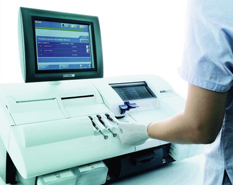
Arterial blood gas analyser (Fig. 13.5)
1. Heparin should be added to the sample to prevent clotting during the analysis. The heparin should only fill the dead space of the syringe and form a thin film on its interior. Excess heparin, which is acidic, lowers the pH of the sample.
2. The presence of air bubbles in the sample increases the oxygen partial pressure and decreases carbon dioxide partial pressure.
3. An old blood sample has a lower pH and oxygen partial pressure and a higher carbon dioxide partial pressure. If there is a need to delay the analysis (e.g. machine self-calibration), the sample should be kept on ice.
Polarographic (Clark) oxygen electrode
This measures the oxygen partial pressure in a blood (or gas) sample (Fig. 13.6).
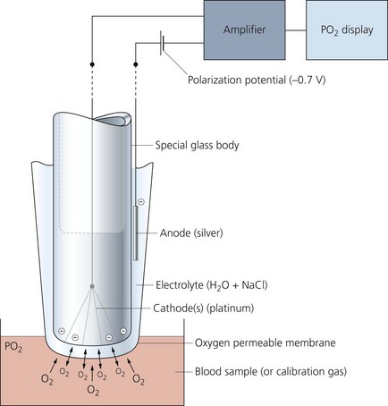
Mechanism of action
1. Oxygen molecules cross the membrane into the electrolyte solution at a rate proportional to their partial pressure in the sample.
2. A very small electric current flows when the polarization potential is applied across the electrode in the presence of oxygen molecules in the electrolyte solution. Electrons are donated by the anode and accepted by the cathode, producing an electric current within the solution. The circuit is completed by the input terminal of the amplifier.
3. The oxygen partial pressure in the sample can be measured since the amount of current is linearly proportional to the oxygen partial pressure in the sample.
pH electrode
This measures the activity of the hydrogen ions in a sample. Described mathematically, it is:
It is a versatile electrode which can measure samples of blood, urine or CSF (Fig. 13.7).
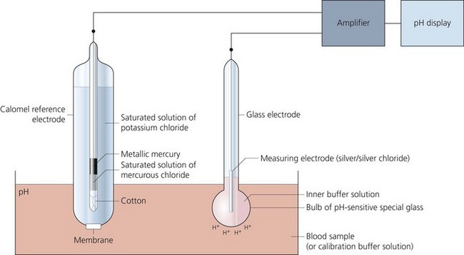
Fig. 13.7 Mechanism of action of the pH electrode.
Components
1. A glass electrode (silver/silver chloride) incorporating a bulb made of pH-sensitive glass holding a buffer solution.
2. A calomel reference electrode (mercury/mercury chloride) which is in contact with a potassium chloride solution via a cotton plug. The arterial blood sample is in contact with the potassium chloride solution via a membrane.
3. A meter to display the potential difference across the two electrodes.
Mechanism of action
1. The reference electrode maintains a constant potential.
2. The pH within the glass remains constant due to the action of the buffer solution. However, a pH gradient exists between the sample and the buffer solution. This gradient results in an electrical potential.
3. Using the two electrodes to create an electrical circuit, the potential can be measured. One electrode is in contact with the buffer and the other is in contact with the blood sample.
4. A linear electrical output of about 60 mV per unit pH is produced.
5. The two electrodes are kept at a constant temperature of 37°C.
Carbon dioxide electrode (Severinghaus electrode)
A modified pH electrode is used to measure carbon dioxide partial pressure, as a result of change in the pH of an electrolyte solution (Fig. 13.8).
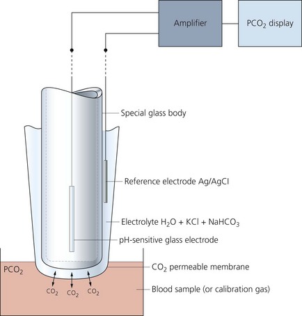
Mechanism of action
1. Carbon dioxide (not hydrogen ions) diffuses in both directions until equilibrium exists across the membrane between the sample and the electrolyte solution.
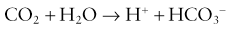
2. Carbon dioxide reacts with the water present in the electrolyte solution producing hydrogen ions resulting in a change in pH:
3. The change in pH is measured by the glass electrode.
4. The electrode should be maintained at a temperature of 37°C. Regular calibration is required.
Intra-aortic balloon pump (IABP)
This is a catheter incorporating a balloon which is inserted into the aorta to support patients with severe cardiac failure. Its core principle is synchronized counterpulsation. It is usually inserted using a percutaneous femoral approach, over a guidewire, under fluoroscopic or transoesophageal echo guidance. The correct position of the pump is in the descending aorta, just distal to the left subclavian artery (Fig 13.9).
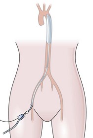
Fig. 13.9 The intra-aortic balloon pump in situ.
Components
1. A 7- up to 8-FG catheter with a balloon.
2. The catheter has two lumens, an outer lumen for helium gas exchange to and from the balloon and a fluid-filled central lumen for continuous aortic pressure monitoring via a transducer. The most modern versions use fibre-optics instead to monitor aortic pressure, which is faster and more sensitive, generating faster response times.
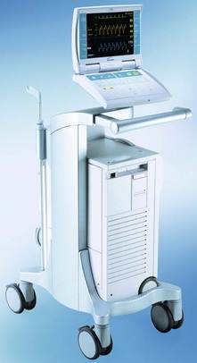
3. The usual volume of the balloon is 40 mL. A 34-mL balloon is available for small individuals. The size of the balloon should be 80–90% of the diameter of the aorta. The pump is attached to a console (Fig. 13.10) which controls the flow of helium in and out of the balloon and monitors the patient’s blood pressure and ECG. The console allows the adjustment of the various parameters in order to optimize counterpulsation.
Mechanism of action
1. The balloon is inflated in early diastole, immediately after the closure of the aortic valve. This leads to an increase in peak diastolic blood pressure (diastolic augmentation) and an increase in coronary artery perfusion pressure. This increases myocardial oxygen supply. Inflation should be at the dicrotic notch on the arterial pressure waveform (Fig. 13.11).
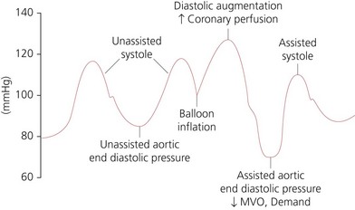
2. The balloon is deflated at the end of diastole just before the aortic valve opens and remains deflated during systole. This leads to a decrease in aortic end-diastolic pressure causing a decrease in left ventricular afterload and decreased myocardial oxygen demand. This will lead to an increase in left ventricular performance, stroke work and ejection fraction. Deflation should be at the lowest point of the arterial diastolic pressure.
3. During myocardial ischaemia, the main benefits of the IABP are the reduction of myocardial oxygen demand (by lowering of the left ventricular pressure) and the increase in myocardial oxygen supply (by increasing the coronary artery perfusion).
4. The effectiveness of the balloon depends on the ratio of the balloon to aorta size, heart rate and rhythm, compliance of the aorta and peripheral vessels and the precise timing of the counterpulsation. Correctly timed IABP should be able to increase the augmented diastolic pressure to higher then the systolic pressure. IABP is expected to increase diastolic pressure by 30%, decrease the systolic pressure by 20% and improve cardiac output by 20%.
Intravenous giving sets
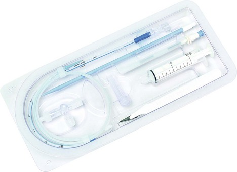
These are designed to administer intravenous fluids, blood and blood products (Fig. 13.12).

Components
a) A clear plastic tube of about 175 cm in length and 4 mm in internal diameter. One end is designed for insertion into the fluid bag whereas the other end is attached to an intravascular cannula with a Luer-lock connection.
b) Blood giving sets have a filter with a mesh of about 150–200 µm and a fluid chamber (Fig. 13.12B). Giving sets with finer mesh filter of about 40 µm are available (Fig. 13.12C).
c) Some designs have a one-way valve and a three-way tap attachment or a rubber injection site at the patient’s end. The maximum size needle used for injection should be 23 G.
d) A flow controller determines the drip rate (20 drops of clear fluid is 1 mL and 15 drops of blood is 1 mL).
2. Paediatric set (Fig. 13.12D):
a) In order to attain accuracy, a burette (30–200 mL) in 1 mL divisions is used to measure the volume of fluid to be infused. The burette has a filter, air inlet and an injection site on its top. At the bottom, there is a flap/ball valve to prevent air entry when the burette is empty.
b) There are two flow controllers: one is between the fluid bag and the burette and is used to fill the burette; the second is between the burette and the patient and controls the drip rate. An injection site should be close to the patient to reduce the dead space.
c) Drop size is 60 drops per 1 mL of clear fluid. A burette with a drop size similar to the adult’s version (15 drops per mL) is used for blood transfusion.
d) 0.2-micron filters can be added in line to filter out air and foreign bodies, e.g. glass or plastic particles. Infusion-related thrombophlebitis can be reduced by the use of these filters.
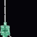
Intravenous cannulae
Intravenous cannulae are made of plastic. They are made by different manufacturers with different characteristics (Fig. 13.13).
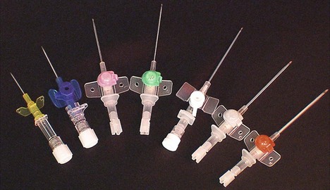
Fig. 13.13 A range of intravenous cannulae.
Intravenous cannulae can be either with or without a port. Some designs offer protection against the risk of needle stick injuries (Fig. 13.14), covering the sharp needle tip with a blunt end.
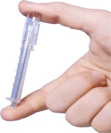
Fig. 13.14 Smith’s Medical Protective Acuvance cannula designed to reduce the risk of needle stick injury.
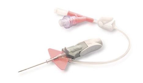
More recent designs are the ‘closed and integrated’ cannulae (Fig. 13.15). A ‘closed’ system may offer better protection against bacterial exposure than conventional ‘open’ ports. As the blood does not naturally escape from the catheter hub, these devices further minimize the risk of exposing the clinician to blood during the insertion procedure.
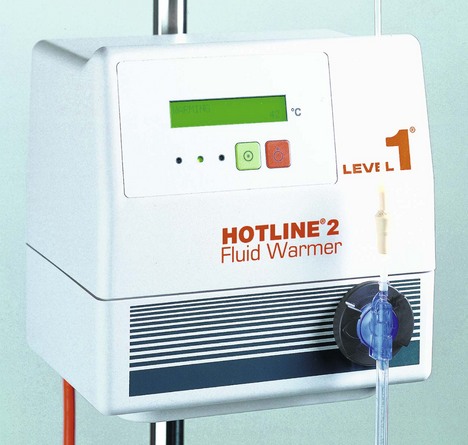
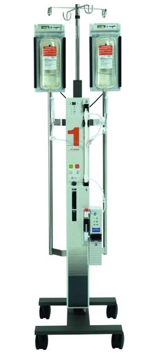
Blood warmers
These are used to warm blood (and other fluids) before administering them to the patient. The aim is to deliver blood/fluids to the patient at 37°C. At this temperature, there is no significant haemolysis or increase in osmotic fragility of the red blood cells. There are various designs with the coaxial fluid/blood warmer devices are most popular (Fig. 13.16). A coaxial tubing is used to heat and deliver the fluids to the patient. The outside tubing carries heated sterile water. The inside tubing carries the intravenous fluid. The sterile water is heated to 40°C and stored by the heating case. The water is circulated through the outside tubing. The intravenous fluid does not come in contact with the circulating water. The coaxial tubing extends to the intravenous cannula reducing the loss of heat as fluid is exposed to room temperature.
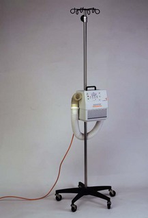
For patients requiring large and rapid intravenous therapy, special devices are used to deliver warm fluids (Fig. 13.17). Fluids are pressurized to 300 mmHg and warmed with a countercurrent recirculation fluid at a temperature of 42°C.
Defibrillator
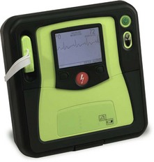
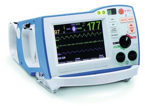
This is a device that delivers electrical energy to the heart causing simultaneous depolarization of an adequate number of myocardial cells to allow a stable rhythm to be established. Defibrillators can be divided into the automated external defibrillators (AEDs) (Fig. 13.19) and manual defibrillators (Fig. 13.20). AEDs offer interaction with the rescuer through voice and visual prompts.
Mechanism of action
1. DC energy rather than AC energy is used. DC energy is more effective causing less myocardial damage and being less arrhythmogenic than AC energy. The lower the energy used, the less the damage to the heart.
2. Transformers are used to step up mains voltage from 240 V AC to 5000–9000 V AC. A rectifier converts it to 5000 V DC. A variable voltage step-up transformer is used so that different amounts of charge may be selected. Most defibrillators have internal rechargeable batteries that supply DC in the absence of mains supply. This is then converted to AC by means of an inverter, and then amplified to 5000 V DC by a step-up transformer and rectifier (Fig. 13.21).
Fig. 13.21 Defibrillator electric circuit.
3. The DC shock is of brief duration and produced by discharge from a capacitor. The capacitor stores energy in the form of an electrical charge, and then releases it over a short period of time. The current delivered is maintained for several milliseconds in order to achieve successful defibrillation. As the current and charge delivered by a discharging capacitor decay rapidly and exponentially, inductors are used to prolong the duration of current flow.
4. The external paddles/pads are positioned on the sternum and on the left midaxillary line (fifth–sixth rib). An alternative placement is one paddle positioned anteriorly over the left precordium and the other positioned posteriorly behind the heart. Firm pressure on the paddles is required in order to reduce the transthoracic impedance and achieve a higher peak current flow. Using conductive gel pads helps in reducing the transthoracic impedance. Disposable adhesive defibrillator electrode pads are currently used instead of paddles, offering hands-free defibrillation.
5. Most of the current is dissipated through the resistance of the skin and the rest of the tissues and only a small part of the total current (about 35 A) flows through the heart. The impedance to the flow of current is about 50–150 Ohms; however, repeated administration of shocks in quick succession reduces impedance.
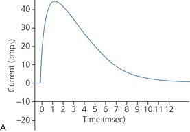
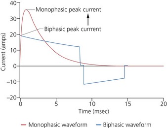
a) Monophasic defibrillators deliver current that is unipolar (i.e. one direction of current flow) (Fig. 13.22A). They are not used in modern practice as they were likely to have waveform modification depending on transthoracic impedance (e.g. larger patients with high transthoracic impedance received considerably less transmyocardial current than smaller patients).
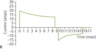
b) Biphasic defibrillators deliver a two-phased current flow in which electrical current flows in one direction for a specified duration, then reverses and flows in the opposite direction for the remaining milliseconds of the electrical discharge. Biphasic defibrillators can either be biphasic truncated exponential (BTE) (Fig. 13.22B) or rectilinear biphasic (RLB) (Fig. 13.22C). Biphasic defibrillators compensate for the wide variations in transthoracic impedance by electronically adjusting the waveform magnitude and duration to ensure optimal current delivery to the myocardium, irrespective of the patient’s size.
c) Monophasic vs biphasic performance: as can be seen in Figure 13.23 the highest part of the current waveform is known as the ‘peak current’ when the most current is flowing. Note the difference in height (amps) between the monophasic peak current and the biphasic peak current. Too much peak current during the shock can injure the heart. It’s the peak current, not energy, that can injure the heart. The goal of defibrillation is to deliver enough current to the heart to stop the lethal rhythm but with a low peak current to decrease risk of injury to the heart muscle.
7. For internal defibrillation, the shock delivered to the heart depends on the size of the heart and the paddles.
8. Some designs have an ECG oscilloscope and paper recording facilities. DC defibrillation can be synchronized with the top of the R-wave in the treatment of certain arrhythmias such as atrial fibrillation.
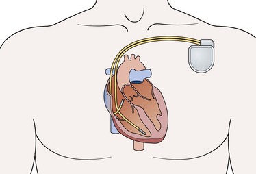
9. The implantable automatic internal defibrillator (Fig. 13.24) is a self-contained diagnostic and therapeutic device placed next to the heart. It consists of a battery and electrical circuitry (pulse generator) connected to one or more insulated wires. The pulse generator and batteries are sealed together and implanted under the skin, usually near the shoulder. The wires are threaded through blood vessels from the implantable cardiac defibrillator (ICD) to the heart muscle. It continuously monitors the rhythm, and when malignant tachyarrhythmias are detected, a defibrillation shock is automatically delivered. ICDs are subject to malfunction due to internal short circuit when attempting to deliver an electrical shock to the heart or due to a memory error. Newer devices also provide overdrive pacing to electrically convert a sustained ventricular tachycardia, and ‘back-up’ pacing if bradycardia occurs. They also offer a host of other sophisticated functions (such as storage of detected arrhythmic events and the ability to do ‘non-invasive’ electrophysiologic testing).
Chest drain
Used for the drainage of air, blood and fluids from the pleural space.
Mechanism of action
1. An air-tight system is required to maintain a subatmospheric intrapleural pressure. The underwater seal acts as a one-way valve through which air is expelled from the pleural space and prevented from re-entering during the next inspiration. This allows re-expansion of the lung after a pneumothorax and restores haemodynamic stability by minimizing mediastinal shift.
2. Under asepsis, skin and subcutaneous tissues are infiltrated with local anaesthetic at the level of the fourth–fifth intercostal space in the midaxillary line. The chest wall is incised and blunt dissection using artery forceps through to the pleural cavity is performed. Using the tip of the finger, adherent lung is swept away from the insertion site.
3. The drain is inserted into the pleural cavity and slid into position (usually towards the apex). The drain is then connected to an underwater seal device.
4. Some designs have a flexible trocar to reduce the risk of trauma.
5. The drainage tube is submerged to a depth of 1–2 cm in the collection chamber (Fig. 13.26). This ensures minimum resistance to drainage of air and maintains the underwater seal even in the face of a large inspiratory effort.
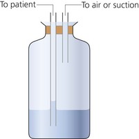
Fig. 13.26 Chest drain underwater seal.
6. The collection chamber should be about 100 cm below the chest as subatmospheric pressures up to −80 cm H2O may be produced during obstructed inspiration.
7. A Heimlich flutter one-way valve can be used instead of an underwater seal, allowing better patient mobility.
8. Drainage can be allowed to occur under gravity or suction of about −15–20 mmHg may be applied.
Problems in practice and safety features
1. Retrograde flow of fluid may occur if the collection chamber is raised above the level of the patient. The collection chamber should be kept below the level of the patient at all times to prevent fluid being siphoned into the pleural space.
2. Absence of oscillations may indicate obstruction of the drainage system by clots or kinks, loss of subatmospheric pressure or complete re-expansion of the lung.
3. Persistent bubbling indicates a continuing bronchopleural air leak.
4. Clamping a pleural drain in the presence of a continuing air leak may result in a tension pneumothorax.
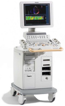
The ultrasound machine (Fig. 13.27)
Mechanism of action
1. The probe transmits and receives the ultrasound beam once placed in contact with the skin via ‘acoustic coupling’ jelly.
2. Ultrasound is created by converting electrical energy into mechanical vibration utilizing the piezoelectric (PE) effect. The PE materials vibrate when a varying voltage is applied. The frequency of the voltage applied determines the frequency of the sound waves produced. The thickness of the PE element determines the frequency at which the element will vibrate most efficiently, i.e. its resonant frequency (RF). RF occurs when the thickness of element is half the wavelength of the sound wave generated.
3. An image is generated when the pulse wave emitted from the transducer is transmitted into the body, reflected off the tissue interface and returned to the transducer. Returning US waves cause PE crystals (elements) within the transducer to vibrate. This causes the generation of a voltage. Therefore, the same crystals can be used to send and receive sound waves.
4. Two-dimensional images of structures are displayed. Procedures requiring precise needle placement such as venous cannulation or nerve blocks can be performed under direct ultrasound control. This helps to minimize the possible risks of the procedure.
5. The image can be displayed in a number of modes:
a) A-mode (amplitude); not used any more
b) B-mode (brightness); most commonly used for regional anaesthesia
c) M-mode (motion); most commonly for cardiac and foetal imaging
6. Structures can then be identified via their ultrasound characteristics and anatomical relationships.
7. Increasing the depth allows visualization of deeper structures. The depth of the image should be optimized so that the target is centred in the display image.
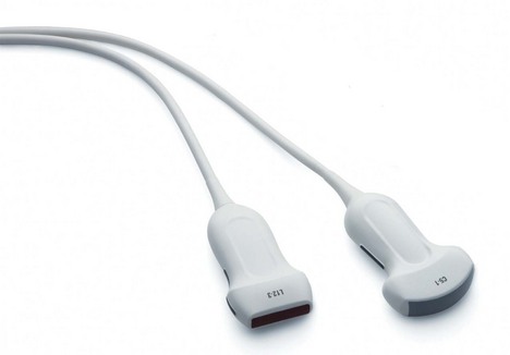
8. Transducer probes come in many shapes and sizes (Fig. 13.28). The shape of the probe determines its field of view, and the frequency of emitted sound waves determines how deep the sound waves penetrate and the resolution of the image.
Problems in practice and safety features
1. One of the commonest mistakes in ultrasound imaging is the use of incorrect gain settings. Insufficient gain can result in missed structures of low reflectivity, such as thrombus. Excessive gain can result in artifacts.
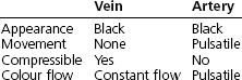
2. The characteristics differentiating vein from artery are listed below.
Alaour B., English W. Intra-aortic balloon pump counterpulsation. World Anaesthesia Society. Online. Available at http://www.anaesthesiauk.com/Documents/220%20Intra-aortic%20Balloon%20Pump%20Counterpulsation.pdf, 2011.
MHRA. Infusion systems DB 2003(02) v2.0. Online. Available at http://www.mhra.gov.uk/Publications/Safetyguidance/DeviceBulletins/CON007321, 2010.
MHRA. Medical device alert: all chest drains when used with high-flow, low-vacuum suction systems (wall mounted) (MDA/2010/040). Online. Available at http://www.mhra.gov.uk/Publications/Safetywarnings/MedicalDeviceAlerts/CON081890, 2010.
MHRA. Medical device alert: intravenous (IV) extension sets with multiple ports: all brands (MDA/2010/073). Online. Available at http://www.mhra.gov.uk/Publications/Safetywarnings/MedicalDeviceAlerts/CON093966, 2010.
MHRA. Medical device alert: IV extension sets with multiple ports and vented caps. Various manufacturers (MDA/2010/068). Online. Available at http://www.mhra.gov.uk/Publications/Safetywarnings/MedicalDeviceAlerts/CON093757, 2010.
MHRA. Medical device alert: SleepStyle CPAP devices manufactured by Fisher & Paykel Healthcare (MDA/2010/076). Online. Available at http://www.mhra.gov.uk/Publications/Safetywarnings/MedicalDeviceAlerts/CON094175, 2010.
NHS. Chest drains: risks associated with the insertion of chest drains. Online. Available at http://www.nrls.npsa.nhs.uk/resources/?entryid45=59887&p=10, 2009.
NHS. Non-invasive ventilation. Online. Available at http://www.nrls.npsa.nhs.uk/resources/?entryid45=83759&p=2, 2010.
In the following lists, which of the statements (a) to (e) are true?
a) Alternating current is commonly used instead of direct current.
b) The electric current released is measured in watts.
c) Consists of an inductor which releases the electric current.
e) The same amount of electrical energy is used for external and internal defibrillation.
2. Concerning arterial blood gases analysis:
a) Excess heparin in the sample increases the hydrogen ion concentration.
b) Blood samples with air bubbles have a lower oxygen partial pressure.
c) If there is delay in the analysis, the blood sample can be kept at room temperature.
d) Normal H+ ion concentration is 40 mmol/L.
e) CO2 partial pressure can be measured by measuring the pH.
3. Concerning the CO2 electrode:
a) KCl and NaHCO3 are used as electrolyte solutions.
b) A carbon dioxide-sensitive glass electrode is used.
c) The electrical signal generated is directly proportional to the log of CO2 tension in the sample.
a) CPAP is a controlled ventilation mode.
b) It can improve oxygenation by increasing the FRC.
c) Pressures of up to 15 kPa are commonly used.
a) Solutes of molecular weight up to 20 000 Da can pass through the filter.
b) It should not be used in the cardiovascularly unstable patient.
c) Blood flows of 150–300 mL/min are generally used.
d) Warfarin is routinely used to prevent the filter clotting.
a) The usual volume of the balloon is 40 mL.
b) The inflation of the balloon occurs at the upstroke of the arterial waveform.
c) The deflation of the balloon occurs at the end of diastole just before the aortic valve opens.
a) The underwater seal chamber can be positioned at any level convenient to the patient.
b) Persistent air bubbling may be a sign of a continuing bronchopleural air leak.
c) They function by expelling intrapleural fluids during deep inspiration.
d) Negative pressure of about −15–20 mmHg may be applied to help in the drainage.
e) Clamping a pleural drain in the presence of a continuing air leak may result in a tension pneumothorax.
a) False. DC current is used as the energy generated is more effective and causes less myocardial damage. Also DC energy is less arrhythmogenic than AC energy.
b) False. Joules, not watts, are used to measure the electric energy released.
c) False. The defibrillator consists of a capacitor that stores then discharges the electric energy in a controlled manner. Step-up transformers are used to change mains voltage to a much higher AC voltage. A rectifier converts that to a DC voltage. Inductors are used to prolong the duration of current flow as the current and charge delivered by a discharging capacitor decay rapidly and exponentially.
d) True. Because of the high energy release, skin burns can be caused by defibrillators especially if gel pads are not used.
e) False. The amount of electrical energy used in internal defibrillation is a very small fraction of that used in external defibrillation. In internal defibrillation, the energy is delivered directly to the heart. In external defibrillation, a large proportion of the energy is lost in the tissues before reaching the heart.
2. Concerning arterial blood gases analysis:
a) True. Heparin is added to the blood sample to prevent clotting during the analysis. Heparin should only fill the dead space of the syringe and form a thin layer on its interior. Heparin is acidic and in excess will increase the hydrogen ion concentration (lowering the pH) of the sample.
b) False. As air consists of about 21% oxygen in nitrogen, the addition of an air bubble(s) to the blood sample will increase the oxygen partial pressure in the sample.
c) False. At room temperature, the metabolism of the cells in the blood sample will continue. This leads to a low oxygen partial pressure and a high H+ concentration and CO2 partial pressure. If there is a delay in the analysis, the sample should be kept on ice.
d) False. The normal H+ concentration is 40 nanomol/L, which is equivalent to a pH of 7.4.
e) True. CO2 partial pressure in a sample can be measured by measuring the changes in pH of an electrolyte solution using a modified pH electrode. The CO2 diffuses across a membrane separating the sample and the electrolyte solution. The CO2 reacts with the water present producing H+ ions resulting in changes in pH.
3. Concerning the carbon dioxide electrode:
a) True. KCl, NaHCO3 and water are the electrolyte solutions used. The CO2 reacts with the water producing hydrogen ions.
b) False. A pH-sensitive glass electrode is used to measure the changes in pH caused by the formation of H+ ions resulting from the reaction between water and CO2.
c) True. The electrical signal generated at the electrode is directly proportional to the pH of the sample or the −log of H+ concentration. The latter is related to the CO2 tension in the sample.
d) False. The CO2 electrode has a slow response time as the CO2 takes 2–3 min to diffuse across the membrane.
e) False. The CO2 electrode, like the pH electrode, should be kept at 37°C. Dissociation of acids or bases changes when temperature changes.
a) False. CPAP is continuous positive airway pressure used in spontaneously breathing patients via a face mask or a tracheal tube.
b) True. Oxygenation can be improved by CPAP as the alveoli are held open throughout the ventilatory cycle preventing airway closure thus increasing the FRC.
c) False. Pressures of up to 15 cm H2O are commonly used during CPAP.
d) False. CPAP reduces the cardiac output (similar to PEEP, although to a lesser extent). The arterial oxygenation might improve with the application of CPAP, but oxygen delivery might be reduced because of the reduced cardiac output.
e) True. A nasogastric tube is inserted in patients with depressed consciousness level to prevent gastric distension.
a) True. Solutes of up to 20 000 Da molecular weight are carried along the semipermeable membrane with the fluid by solvent drag (convection).
b) False. One of the reasons for the popularity of haemofiltration in the intensive care unit setup is that it has a higher tolerability in cardiovascularly unstable patients.
c) True. Although blood flows of 30–750 mL/min can be achieved during haemofiltration, blood flows of 150–300 mL/min are commonly used. This gives a filtration rate of 25–40 mL/min.
d) False. Heparin is the anticoagulant of choice during haemofiltration. If there is a contraindication for its use, prostacyclin can be used instead.
e) False. The filters have a large surface area with large pore size and are packed in such a way as to ensure a high surface area to volume ratio. The optimal surface area is 0.5–1.5 m2.
a) True. The usual volume of the balloon is 40 mL. A smaller version, 34 mL, can be used in small patients. The size of the balloon should be 80–90% of the diameter of the aorta.
b) False. The balloon should be inflated in early diastole immediately after the closure of the aortic valve at the dicrotic notch of the arterial waveform. This leads to an increase in coronary artery perfusion pressure.
c) True. This leads to a decrease in aortic end-diastolic pressure so reducing the left ventricular afterload and myocardial oxygen demand.
d) False. Aortic dissection is one of the absolute contraindications to intra-aortic balloon pump.
e) True. Helium is used to inflate the balloon. Because of its physical properties (low density) it allows rapid and complete balloon inflation and deflation.
a) False. The collection chamber should be about 100 cm below the chest as subatmospheric pressures up to −80 cm H2O may be produced during obstructed inspiration. Retrograde flow of fluid may occur if the collection chamber is raised above the level of the patient.
c) False. Deep inspiration helps in expanding the lung whereas deep expiration helps in the drainage of fluids from the pleural space.
d) True. Drainage can be allowed to occur under gravity, or suction of about −15–20 mmHg may be applied.