Chapter 7 Ablation Energy Sources
Radiofrequency Ablation
Biophysics of Radiofrequency Energy
Radiofrequency (RF) refers to the portion of the electromagnetic spectrum in which electromagnetic waves can be generated by alternating current fed to an antenna.1 Electrosurgery ablation currently uses hectomeric wavelengths found in band 6 (300 to 3000 kHz), which are similar to those used for broadcast radio. However, the RF energy is electrically conducted, not radiated, during catheter ablation. The RF current is similar to low-frequency alternating current or direct current with regard to its ability to heat tissue and create a lesion, but it oscillates so rapidly that cardiac and skeletal muscles are not stimulated, thereby avoiding induction of arrhythmias and decreasing the pain perceived by the patient. RF current rarely induces rapid polymorphic arrhythmias; such arrhythmias can be observed in response to low-frequency (60-Hz) stimulation. Frequencies higher than 1000 kHz are also effective in generating tissue heating; however, such high frequencies are associated with considerable energy loss along the transmission line. Therefore, frequencies of the RF current commonly used are in the range of 300 to 1000 kHz, a range that combines efficacy and safety.2,3
Radiofrequency Energy Delivery
Delivery of RF energy depends on the establishment of an electrical circuit involving the human body as one of its in-series elements. The RF current is applied to the tissue via a metal electrode at the tip of the ablation catheter and is generally delivered in a unipolar fashion between the tip electrode and a large dispersive electrode (indifferent electrode, or ground pad) applied to the patient’s skin. The polarity of connections from the electrodes to the generator is not important because the RF current is an alternating current. Bipolar RF systems also exist, in which the current flows between two closely apposed small electrodes, thus limiting the current flow to small tissue volumes interposed between the metal conductors. Bipolar systems, partly because of their relative safety, are now the preferred tools in electrosurgery (oncology, plastic surgery, and ophthalmology). Their clinical application for catheter-based ablation has not yet been evaluated.2,3
The system impedance comprises the impedance of the generator, transmission lines, catheter, electrode-tissue interface, dispersive electrode-skin interface, and interposed tissues. As electricity flows through a circuit, every point of that circuit represents a drop in voltage, and some energy is dissipated as heat. The point of greatest drop in line voltage represents the area of highest impedance and is where most of that electrical energy becomes dissipated as heat. Therefore, with excessive electrical resistance in the transmission line, the line actually warms up and power is lost. Current electrical conductors from the generator all the way through to the patient and from the dispersive electrode back to the generator have low impedance, to minimize power loss.2,3
With normal electrode-tissue contact, only a fraction of all power is effectively applied to the tissue. The rest is dissipated in the blood pool and elsewhere in the patient. With an ablation electrode in contact with the endocardial wall, part of the electrode contacts tissue and the rest contacts blood, and the RF current flows through both the myocardium and the blood pool in contact with the electrode. The distribution between both depends on the impedance of both routes and also on how much electrode surface contacts blood versus endocardial wall. Whereas tissue heating is the target of power delivery, the blood pool is the most attractive route for RF current because blood is a better conductor and has significantly lower impedance than tissue and because the contact between electrode and blood is often better than with tissue. Therefore, with normal electrode-tissue contact, much more power is generally delivered to blood than to cardiac tissue.2,4
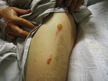
After leaving the electrode-blood-tissue interface, the current flows through the thorax to the indifferent electrode. Part of the RF power is lost in the patient’s body, including the area near the patch. Dissipation of energy can occur at the dispersive electrode site (at the contact point between that ground pad and the skin) to a degree that can limit lesion formation. In fact, if ablation is performed with a high-amplitude current (more than 50 W) and skin contact by the dispersive electrode is poor, it is possible to cause skin burns (Fig. 7-1).1 Nevertheless, because the surface area of the ablation electrode (approximately 12 mm2) is much smaller than that of the dispersive electrode (approximately 100 to 250 cm2), the current density is higher at the ablation site, and heating occurs preferentially at that site, with no significant heating occurring at the dispersive electrode.5
The dispersive electrode may be placed on any convenient skin surface. The geometry of the RF current field is defined by the geometry of the ablation electrode and is relatively uniform in the region of volume heating. Thus, the position of the dispersive electrode (on the patient’s back or thigh) has little effect on impedance, voltage, current delivery, catheter tip temperature, or geometry of the resulting lesion.2,3,5
The size of the dispersive electrode, however, is important. Sometimes it is advantageous to increase the surface area of the dispersive electrode. This increase leads to lower impedance, higher current delivery, increased catheter tip temperatures, and more effective tissue heating. This is especially true in patients with baseline system impedance greater than 100 Ω. Moreover, when the system is power limited, as with a 50-W generator, heat production at the catheter tip varies with the proportion of the local electrode-tissue interface impedance to the overall system impedance. If the impedance at the skin-dispersive electrode interface is high, then a smaller amount of energy is available for tissue heating at the electrode tip. Therefore, when ablating certain sites, adding a second dispersive electrode or optimizing the contact between the dispersive electrode and skin should result in relatively more power delivery to the target tissue.5,6
Tissue Heating
During alternating current flow, charged carriers in tissue (ions) attempt to follow the changes in the direction of the alternating current, thus converting electromagnetic (current) energy into molecular mechanical energy or heat. This type of electric current-mediated heating is known as ohmic (resistive) heating. Using Ohm’s law, with resistive heating, the amount of power (= heat) per unit volume equals the square of current density times the specific impedance of the tissue. With a spherical electrode, the current flows outward radially, and current density therefore decreases with the square of distance from the center of the electrode. Consequently, power dissipation per unit volume decreases with the fourth power of distance. The thickness of the electrode eliminates the first steepest part of this curve, however, and the decrease in dissipated power with distance is therefore somewhat less dramatic.2,3
Approximately 90% of all power that is delivered to the tissue is absorbed within the first 1 to 1.5 mm from the electrode surface. Therefore, only a thin rim of tissue in immediate contact with the RF electrode is directly heated (within the first 2 mm of depth from the electrode). The remainder of tissue heating occurs as a result of heat conduction from this rim to the surrounding tissues. On initiation of fixed-level energy application, the temperature at the electrode-tissue interface rises monoexponentially to reach steady state within 7 to 10 seconds, and the steady state is usually maintained between 80° and 90°C. However, whereas resistive heating starts immediately with the delivery of RF current, conduction of heat to deeper tissue sites is relatively slow and requires 1 to 2 minutes to equilibrate (thermal equilibrium). Therefore, the rate of tissue temperature rise beyond the immediate vicinity of the RF electrode is much slower, resulting in a steep radial temperature gradient as tissue temperature decreases radially in proportion to the distance from the ablation electrode; however, deep tissue temperatures continue to rise for several seconds after interruption of RF delivery (the so-called thermal latency phenomenon).4 Therefore, RF ablation requires at least 30 to 60 seconds to create full-grown lesions. In addition, when temperature differences between adjacent areas develop because of differences in local current density or local heat capacity, heat conducts from hotter to colder areas, thus causing the temperature of the former to decrease and that of the latter to increase. Furthermore, heat loss to the blood pool at the surface and to intramyocardial vessels determines the temperature profile within the tissue.2,3
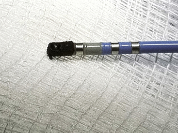
At steady state, the lesion size is proportional to the temperature measured at the interface between the tissue and the electrode, as well as to the RF power amplitude. By using higher powers and achieving higher tissue temperatures, the lesion size can be increased. However, once the peak tissue temperature exceeds the threshold of 100°C, boiling of the plasma at the electrode-tissue interface can ensue. When boiling occurs, denatured serum proteins and charred tissue form a thin film that adheres to the electrode, thus producing an electrically insulating coagulum, which is accompanied by a sudden increase in electrical impedance that prevents further current flow into the tissue and further heating.2,3
Convective Cooling
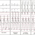
The dominant factor opposing effective heating of myocardium is the convective heat loss into the circulating blood pool. Because the tissue surface is cooled by the blood flow, the highest temperature during RF delivery occurs slightly below the endocardial surface. Consequently, the width of the endocardial lesion matures earlier than the intramural lesion width (20 seconds versus 90 to 120 seconds). Therefore, the maximum lesion width is usually located intramurally, and the resultant lesion is usually teardrop shaped, with less necrosis of the superficial tissue.3
As the magnitude of convective cooling increases (e.g., unstable catheter position, poor catheter-tissue contact, or high blood flow in the region of catheter position), there is decreased efficiency of heating as more energy is carried away in the blood and less energy is delivered to the tissue. When RF power is limited, lesion size is reduced by such convective heat loss. On the other hand, when RF power delivery is not limited, convective cooling allows for more power to be delivered into the tissue, and higher tissue temperatures can be achieved (despite low temperatures measured by the catheter tip sensors), resulting in larger lesion size, without the risk of overheating and coagulum formation.2,3
The concept of convective cooling can explain why there are few coronary complications with conventional RF ablation. Coronary arteries act as a heat sink; substantive heating of vascular endothelium is prevented by heat dissipation in the high-velocity coronary blood flow, even when the catheter is positioned close to the vessel. Although this is advantageous, because coronary arteries are being protected, it can limit success of the ablation lesion if a large perforating artery is close to the ablation target.5
Catheter Tip Temperature
Ablation catheter tip temperature depends on tissue temperature, convective cooling by the surrounding blood, tissue contact of the ablation electrode, electrode material and its heat capacity, and type and location of the temperature sensor.2,7
Catheter tip temperature is measured by a sensor located in the ablation electrode. There are two different types of temperature sensors: thermistors and thermocouples. Thermistors require a driving current, and the electrical resistance changes as the temperature of the electrical conductor changes. More frequently used are thermocouples, which consist of copper and constantan wires and are incorporated in the center of the ablation electrode. Thermocouples are based on the so-called Seebeck effect; when two different metals are connected (sensing junction), a voltage can be measured at the reference junction that is proportional to the temperature difference between the two metals.2,7
Several other factors can increase the disparity between catheter tip temperature and tissue temperature, including catheter tip irrigation, large ablation electrode size, and poor electrode-tissue contact. Catheter tip irrigation increases the disparity between tissue temperature and electrode temperature because it results in cooling of the ablation electrode, but not the tissue. With a large electrode tip, a larger area of the electrode tip is exposed to the cooling effects of the blood flow than with standard tip lengths, thus resulting in lower electrode temperatures. Similarly, with poor electrode-tissue contact, less electrode material is in contact with the tissue, and heating of the tip by the tissue occurs at a lower rate, resulting in relatively low tip temperatures.3,6–8
Pathophysiology of Lesion Formation by Radiofrequency Ablation
Cellular Effects of Radiofrequency Ablation
The primary mechanism of tissue injury by RF ablation is likely to be thermally mediated. Hyperthermic injury to the myocyte is both time- and temperature-dependent, and it can be caused by changes in the cell membrane, protein inactivation, cytoskeletal disruption, nuclear degeneration, or other potential mechanisms.2,3
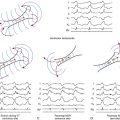
Experimentally, the resting membrane depolarization is related to temperature. In the low hyperthermic range (37° to 45°C), little tissue injury occurs, and a minor change may be observed in the resting membrane potential and action potential amplitude. However, action potential duration shortens significantly, and conduction velocity becomes greater than at baseline. In the intermediate hyperthermic range (45° to 50°C), progressive depolarization of the resting membrane potential occurs, and action potential amplitude decreases. Additionally, abnormal automaticity is observed, reversible loss of excitability occurs, and conduction velocity progressively decreases. In the high temperature ranges (higher than 50°C), marked depolarization of the resting membrane potential occurs, and permanent loss of excitability is observed. Temporary (at temperatures of 49.5° to 51.5°C) and then permanent (at 51.7° to 54.4°C) conduction block develops, and fairly reliable irreversible myocardial injury occurs with a short hyperthermic exposure.3
RF ablation typically results in high temperatures (70° to 90°C) for a short time (up to 60 seconds) at the electrode-tissue interface, but significantly lower temperatures at deeper tissue sites. This leads to rapid tissue injury within the immediate vicinity of the RF electrode but relatively delayed myocardial injury with increasing distance from the RF electrode. Therefore, although irreversible loss of EP function can usually be demonstrated immediately after successful RF ablation, this finding can be delayed because tissue temperatures continue to rise somewhat after termination of RF energy delivery (thermal latency phenomenon). This effect can account for the observation that patients undergoing AV node (AVN) modification procedures who demonstrate transient heart block during RF energy delivery can progress to persisting complete heart block, even if RF energy delivery is terminated immediately. Reversible loss of conduction can be demonstrated within seconds of initiating the RF application, which can be caused by an acute electrotonic effect. On the other hand, there can be late recovery of electrophysiological (EP) function after an initial successful ablation.5
Tissue Effects of Radiofrequency Ablation
Changes in myocardial tissue are apparent immediately on completion of the RF lesion. Pallor of the central zone of the lesion is attributable to denaturation of myocyte proteins (principally myoglobin) and subsequent loss of the red pigmentation. Slight deformation, indicating volume loss, occurs at the point of catheter contact in the central region of lesion formation. The endocardial surface is usually covered with a thin fibrin layer and, occasionally, if a temperature of 100°C has been exceeded, with char and thrombus (Fig. 7-2). In addition, a coagulum (an accumulation of fibrin, platelets, and other blood and tissue components) can form at the ablation electrode because of the boiling of blood and tissue serum.2
On sectioning, the central portion of the RF ablation lesion shows desiccation, with a surrounding region of hemorrhagic tissue and then normal-appearing tissue. Histologic examination of an acute lesion shows typical coagulation necrosis with basophilic stippling consistent with intracellular calcium overload. Immediately surrounding the central lesion is a region of hemorrhage and acute monocellular and neutrophilic inflammation. The progressive changes seen in the evolution of an RF lesion are typical of healing after any acute injury. Within 2 months of the ablation, the lesion shows fibrosis, granulation tissue, chronic inflammatory infiltrates, and significant volume contraction. The lesion border is well demarcated from the surrounding viable myocardium without evidence of a transitional zone. This likely accounts for the absence of proarrhythmic side effects of RF catheter ablation. As noted, because of the high-velocity blood flow within the epicardial coronary arteries, these vessels are continuously cooled and are typically spared from injury, despite nearby delivery of RF energy. However, high RF power delivery in small hearts, such as in pediatric patients, or in direct contact with the vessel can potentially cause coronary arterial injury.3
The border zone around the acute pathological RF lesion accounts for several phenomena observed clinically. The border zone is characterized by marked ultrastructural abnormalities of the microvasculature and myocytes acutely, as well as a typical inflammatory response later. The most thermally sensitive structures appear to be the plasma membrane and gap junctions, which show morphological changes as far as 6 mm from the edge of the pathological lesion. The border zone accounts for documented effects of RF lesion formation well beyond the acute pathological lesion. The progression of the EP effects after completion of the ablation procedure can be caused by further inflammatory injury and necrosis in the border zone region that result in late progression of physiological block and a delayed cure in some cases. On the other hand, initial stunning and then early or late recovery of function can be demonstrated in the border zone, thus accounting for the recovery of EP function after successful catheter ablation in the clinical setting, which can be caused by healing of the damaged, but surviving, myocardium.2
Determinants of Lesion Size
Lesion size is defined as the total volume or dimensions (width and depth) of the lesion. The size of the lesion created by RF power is determined by the amount of tissue heated to more than the critical temperature for producing irreversible myocardial damage (50°C). As noted, only a thin rim (1 to 2 mm) of tissue immediately under the ablating electrode is directly heated. This heat then radiates to adjacent tissue; however, conduction of heat to deeper tissue sites is relatively slow and very inefficient. The distance at which temperature drops to less than 50°C delimits the depth of lesion formation. The use of higher-power output to achieve higher tissue temperatures results in larger lesions by raising the temperature of the rim of resistively heated tissue to substantially more than 50°C for deeper tissue to reach the 50°C threshold required for tissue necrosis. However, the rim of heated tissue in direct contact with the ablating electrode conducts not only to deeper tissue but also to the electrode tip itself. Higher electrode temperatures either limit further energy delivery (in temperature-controlled power delivery mode) or increase electrode impedance as a result of coagulum formation, or both; these effects potentially limit lesion size. Furthermore, tissue temperatures higher than 100°C are unsafe because they are associated with higher risk of steam “pops.” Cooling of the ablating electrode (passively by using a larger electrode length or actively by using catheter irrigation) can help diminish electrode heating, allowing for greater power delivery and creation of larger lesions.9
Electrode-Tissue Contact
The efficiency of energy transfer to the myocardium largely depends on electrode-tissue contact. An improvement in tissue contact leads to a higher amount of RF power that can be effectively delivered to the tissue. Consequently, the same tissue temperatures and lesion size can be reached at a much lower power level. However, at a certain moderate contact force, further increase in contact firmness results in progressively smaller lesions because a lesser amount of RF power is required to reach target temperature.4
Additionally, the surface area at the electrode-tissue interface influences the lesion size. When the catheter is wedged (i.e., between ventricular trabeculae or under a valvular leaflet), the electrode surface area exposed to tissue can be much higher. With half the electrode in contact with blood and the other half in contact with (twice) more resistive tissue, the amount of power delivered to blood is two times higher than the amount of power delivered to tissue (as compared with six times with 25% contact). The result is a more than twofold increase in tissue heating. In practice, however, power output rarely reaches 50 W in these situations; a temperature rise of the ablation electrode signals excessive tissue heating and limits power delivery.4
Electrode Orientation
When the catheter tip is perpendicular to the tissue surface, a much smaller surface area is in contact with the tissue (versus that exposed to the cooling effect of blood flow) than when the catheter electrode tip is lying on its side. Clinically, perpendicular electrode orientation yields larger lesion volumes and uses less power than parallel electrode orientation. However, if the RF power level is adjusted to maintain a constant current density, lesion size will increase proportionally to the electrode-tissue contact area, which is larger with parallel tip orientation. Lesion depth is only slightly affected by catheter tip orientation using 4-mm-long tip catheters, but lesions are slightly longer in the parallel orientation as compared with the perpendicular orientation. Moreover, the character of the lesion created with temperature control depends on the placement of the temperature sensors relative to the portion of the electrode in contact with tissue. Thus, the orientation of the electrode and of its temperature sensors determines the appropriate target temperature required to create maximal lesions while avoiding coagulum formation caused by overheating at any location within the electrode-tissue interface.2,3,10
Electrode Length
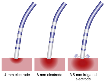
Ablation catheters have tip electrodes that are conventionally 4 mm long and are available in sizes up to 10 mm long (see Fig. 4-6). An increased electrode size reduces the interface impedance with blood and tissue, but the impedance through the rest of the patient remains the same. The ratio between interface impedance and the impedance through the rest of the patient is thus lower with an 8-mm electrode than with a 4-mm electrode, which reduces the efficiency of power transfer to the tissue. Therefore, with the same total power, lesions created with a larger electrode are always smaller than lesions created with a smaller electrode (Fig. 7-3). A larger electrode size also creates a greater variability in power transfer to the tissue because of greater variability of tissue contact, and tissue contact becomes much more dependent on catheter orientation with longer electrodes. Consequently, an 8-mm electrode may require a 1.5 to 4 times higher power level than a 4-mm electrode to create the same lesion size.4
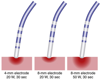
When the power is not limited, however, catheters with large distal electrodes create larger lesions, both by increasing the ablation electrode surface area in contact with the bloodstream, thus resulting in an augmented convective cooling effect, and by increasing the volume of tissue directly heated because of an increased surface area at the electrode-tissue interface (see Fig. 7-3). However, this assumes that the electrode-tissue contact, tissue heat dissipation, and blood flow are uniform throughout the electrode-tissue interface. As the electrode size increases, the likelihood that these assumptions are true diminishes because of variability in cardiac chamber trabeculations and curvature, tissue perfusion, and intracardiac blood flow, which affect the heat dissipation and tissue contact. These factors result in unpredictable lesion size and uniformity for electrodes more than 8 mm long.2,3
There is a potential safety concern with the use of long ablation electrodes because of nonuniform heating, with maximal heating occurring at the electrode edges. Thus, large electrode-tipped catheters with only a single thermistor can underestimate maximal temperature and allow char formation and potential thromboembolic complications. Catheter tips with multiple temperature sensors at the electrode edges may be preferable for temperature feedback. In addition, the greater variation in power delivered to the tissue and the greater discrepancy between electrode and tissue temperature make it difficult to avoid intramural gas explosions and blood clot formation. Another point of concern is that the formation of blood clots may only minimally affect electrode impedance by covering a much smaller part of the electrode surface. Therefore, the lower electrode temperature and the absence of any impedance rise may erroneously suggest a safer ablation process.4
The principal limitations of a large ablation electrode (8 to 10 mm in length) are the reduction in mobility and the flexibility of the catheter, which can impair positioning of the ablation electrode, and a reduction in the resolution of recordings from the ablation electrode, thus making it more difficult to identify the optimal ablation site. A larger electrode dampens the local electrogram, especially that of the distal electrode. With an 8- or 10-mm long distal and a 1-mm short proximal ring electrode, the latter can be the main source for the bipolar electrogram; this then confuses localization of the optimal ablation site. In contrast, a smaller electrode improves mapping accuracy and feedback of tissue heating. Its only drawback is the limited power level that can be applied to the tissue.4
Ablation Electrode Material
Although platinum-iridium electrodes have been the standard for most RF ablation catheters, gold exhibits excellent electrical conductive properties, as well as a more than four times greater thermal conductivity than platinum (300 versus 70 W/m °K), although both materials have similar heat capacities (130 and 135 J/kg °K). The higher thermal conductivity of gold can potentially lead to a higher mean rate of power because of better heat conduction at the tissue-electrode interface and to enhanced cooling as a result of heat loss to the surrounding blood with this electrode material.11 Therefore, gold electrodes allow for greater power delivery to create deeper lesions at a given electrode temperature without impedance increases.12 Enhanced electrode cooling allows for more RF power to be applied at constant temperature, before the temperature limit is reached or before the impedance of the electrode rises.4 However, the higher thermal conductivity of gold electrodes is no longer an advantage in areas of low blood flow (e.g., among myocardial trabeculae), where convective cooling at the electrode tip is minimal. Under these circumstances, electrode materials with a low thermal conductivity can produce larger lesions.3,11
Conflicting results were observed in clinical studies comparing 8-mm gold-tip with platinum-iridium–tip catheters for ablation of the cavotricuspid isthmus.13 During catheter ablation of the slow AVN pathway in patients with AVN reentrant tachycardia (AVNRT), no significant differences were observed between 4-mm gold-tip and platinum-iridium–tip catheters in the primary endpoint or in the increases of power or temperature at any of the measured time points. However, ablation with gold electrodes seemed to be safe and well tolerated and specifically did not increase the risk of AV block. Interestingly, a significant reduction of charring on gold tips was observed, compared with platinum-iridium material, a finding suggesting a possible advantage of this material beyond its better conduction properties.11
Reference Patch Electrode Location And Size
The RF current path and skin reference electrode interface present significant impedance for the ablation current flow, thereby dissipating part of the power. Increasing patch size (or using two patches) provides for increased heating at the electrode-endocardium interface and thus increases ablation efficiency and increases lesion size. On the other hand, the position of the dispersive electrode (on the patient’s back or thigh) has little effect on the size of the resulting lesion.5
Blood Flow
The ablation electrode temperature is dependent on the opposing effects of heating from the tissue and cooling by the blood flowing around the electrode. Because lesion size is primarily dependent on the RF power delivered to the tissue, lesion size varies with the magnitude of local blood flow. At any given electrode temperature, the RF power delivered to the tissue is significantly reduced in areas of low local blood flow (e.g., deep pouch in the cavotricuspid isthmus, dilated and poorly contracting atria, and dilated and poorly contracting ventricles). The reduced cooling associated with low blood flow causes the electrode to reach the target temperature at lower power levels, and if the ablation lesion is temperature-controlled, power delivery will be limited. In these locations, increasing electrode temperature to 65° or 70°C only minimally increases RF power and increases the risk of thrombus formation and impedance rise. In contrast, increasing local blood flow is associated with increased convective cooling of the ablation electrode. Consequently, more power is delivered to the tissue to reach and maintain target temperature, thus resulting in larger lesion volumes.2,3,7
Radiofrequency System Polarity
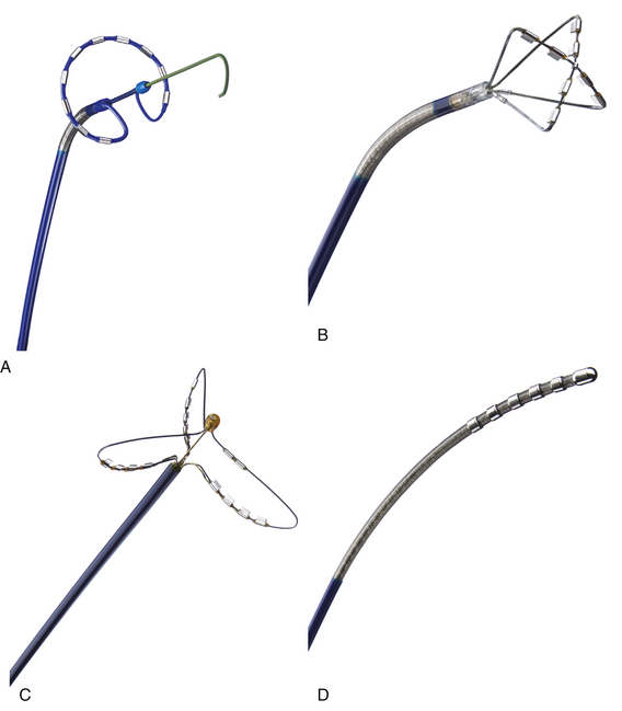
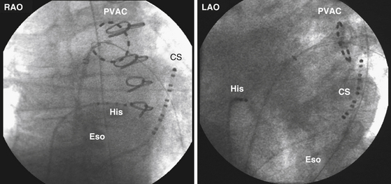
Most RF lesions are created by applying energy in a unipolar fashion between an ablating electrode touching the myocardium and a grounded reference patch electrode placed externally on the skin. The unipolar configuration creates a highly localized lesion, with the least amount of surface injury. Energy can also be applied in a bipolar mode between two endocardial electrodes. Bipolar energy delivery produces larger lesions than unipolar delivery. A novel ablation system (GENius, Ablation Frontiers, Carlsbad, Calif.) has been developed for ablation of atrial fibrillation (AF), in which duty-cycled and alternating unipolar and bipolar (between adjacent electrodes) energy RF ablation is used to create contiguous lesions in the pulmonary vein (PV) antrum using a ring catheter with 10 electrodes (Pulmonary Vein Ablation Catheter [PVAC], Ablation Frontiers, Medtronic Inc., Minneapolis, Minn.) (Figs. 7-4 and 7-5).14 Other catheter designs, which use the same multichannel duty-cycled RF generator, also have been developed for left atrial ablation of fractionated electrograms (Multi-Array Ablation Catheter [MAAC], Ablation Frontiers), septal ablation (Multi-Array Septal Catheter [MASC], Ablation Frontiers), and linear ablation (Tip-Versatile Ablation Catheter [TVAC], Ablation Frontiers) (see Fig. 7-4).15 One advantage of this approach is the simultaneous application of RF energy across an electrode array, intended to create contiguous lesions near an anatomical structure. Additionally, the multielectrode catheters allow selective mapping and ablation through any or all electrodes as required. This system is still undergoing investigation. Another novel ablation catheter system delivers RF energy through a flexible mesh electrode (C.R. Bard, Inc., Billerica, Mass.) that is deployed in the PV ostium. This system is undergoing investigation for PV isolation.16
Monitoring Radiofrequency Energy Delivery
The goal of optimizing RF ablation is to create an adequate-sized lesion while minimizing the chance of an impedance increase because of coagulum formation at the electrode itself, or steam formation within the tissue. As discussed previously, for ablation to be effective, power must be increased sufficiently to achieve temperatures at the tissue directly in contact with the ablating electrode that are substantially higher than 50°C to achieve tissue necrosis. At the same time, for ablation to be safe, the highest tissue temperature must be maintained at less than 100°C to prevent steam pops. Monitoring of RF energy delivery is therefore very important to help achieve successful as well as safe ablation.9
Lesion creation is influenced by many factors, some of which can be controlled, whereas others are variable and can be unpredictable. With standard RF, power delivery is titrated to electrode temperature, typically at 55° to 65°C. Higher temperatures can increase the chance of reaching 100°C at edges of the ablation electrode, thus resulting in coagulum formation. An increase in tissue temperature is accompanied by a decrease in impedance, also a reliable marker of tissue heating. Impedance reduction and temperature rise correlate with both lesion width and depth; maximum temperature rise is best correlated with lesion width, and maximum impedance reduction is best correlated with lesion depth.3,7
In addition to impedance and catheter tip temperature monitoring, reductions in amplitude and steepness of the local electrogram are important indicators for monitoring lesion growth. These indicators, however, apply only to the unipolar distal electrogram. With a bipolar recording, the signal from the ring electrode may dominate the electrogram, and the bipolar amplitude may theoretically even rise during ablation because of a greater difference between the signals from both electrodes.4
Some operators have used visualization of microbubbles on intracardiac ultrasound (ICE) as an indication of excessive tissue heating that is predictive of char and steam pops during ablation and that warrants reduction or termination of RF energy.6
Impedance Monitoring
The magnitude of the current delivered by the RF generator used in ablation is largely determined by the impedance between the ablation catheter and the dispersive electrode. This impedance is influenced by several factors, including intrinsic tissue properties, catheter contact pressure, catheter electrode size, dispersive electrode size, presence of coagulum, and body surface area. Impedance measurement does not require any specific catheter-based sensor circuitry and can be performed with any catheter designed for RF ablation. Larger dispersive electrodes and larger ablation electrodes result in lower impedance.3,7
The impedance drop during RF ablation occurs mainly because of a reversible phenomenon, such as tissue temperature rise, rather than from an irreversible change in tissues secondary to ablation of myocardial tissue. Therefore, impedance provides a useful qualitative assessment of tissue heating; however, it does not correlate well with lesion size.4 A 5- to 10-Ω reduction in impedance is usually observed in clinically successful RF applications, it correlates with a tissue temperature of 55° to 60°C, and it is rarely associated with coagulum formation. Larger decrements in impedance are noted when coagulum formation is imminent. Once a coagulum is formed, an abrupt rise in impedance to more than 250 Ω is usually observed.3,7
The drop in impedance as a monitoring tool has several limitations. When blood flow rates are low, blood can also be heated, and electrode impedance drops accordingly. Moreover, a large rise in tissue temperature at a small contact area and a smaller rise with better tissue contact can result in a similar drop in impedance. Inversely, similar tissue heating with different tissue contact can result in a different change in impedance. In addition, resistive heating nearby is fast, whereas conductive heating to deeper layers is relatively slow. The former, at close distance, has a much greater effect on impedance than the latter, which occurs at greater distance. Like electrode temperature rise, the drop in impedance during RF application is not a reliable parameter for estimating tissue heating and lesion growth.3,4,7
Temperature Monitoring
Monitoring of catheter tip temperature and closed-loop control of power output are useful to avoid excessive heating at the tissue surface, which can result in coagulum formation, and to accomplish effective heating at the target area. However, catheter tip temperature is affected by cooling effects and electrode-tissue contact and thus poorly correlates with lesion size. Tissue temperature can be markedly higher than catheter tip temperature; a higher target temperature can increase the incidence of tissue overheating associated with crater formation and coagulum formation. In high-flow areas, the tip is cooled and more RF power is delivered to the tissue to reach target temperature, thus resulting in relatively large lesions and vice versa.7
As mentioned earlier, temperature monitoring requires a dedicated sensor within the catheter. Two types of sensors are available: thermistor and thermocouple. No catheter or thermometry technology has been demonstrated to be superior in clinical use; however, closed-loop control of power output is easier to use than manual power titration. Conventional electrode catheters with temperature monitoring report the temperature only from the center of the electrode mass with one design or from the apex of the tip of the catheter with another design, and it is likely that the measured temperature underestimates the peak tissue temperature. Therefore, it is best if target temperatures no higher than 70° to 80°C are selected in the clinical setting.3,7
Titration of RF energy using temperature monitoring is usually done automatically by a closed-loop temperature monitoring system. When manual power titration is directed by temperature monitoring, the power initially is set to 20 to 30 W and then is gradually increased until the target temperature is achieved. With both manual and automatic power titration, change in power output is frequently required throughout the RF application to maintain the target temperature. Application of RF energy is continued if the desired clinical effect is observed within 5 to 10 seconds after the target temperature or impedance is achieved. If the desired endpoint does not occur within this time, the failed application is probably because of inadequate mapping. If the target temperature or impedance is not achieved with maximum generator output within 20 seconds, the time it takes to achieve subendocardial steady-state temperature, the RF application can be terminated, and catheter adjustment should be considered to obtain better tissue contact.7
When using 8-mm-tip catheters, a larger portion of the ablation electrode is exposed to the blood and thus cooled by blood flow, and a relatively large difference between catheter tip temperature and tissue temperature can be expected. Consequently, a moderate target temperature (e.g., 60°C) should be chosen; the RF power may be limited to 50 to 60 W to avoid tissue overheating and coagulum formation.3
It is important to recognize that prevention of coagulum formation is difficult, even with temperature and impedance monitoring. The clot first adheres to the tissue because that is the site with the highest temperature and may only loosely attach to the cooler electrode. The denaturized proteins probably have higher electrical impedance than blood, but the contact area with the electrode can be small, and RF impedance may not rise noticeably. The absence of flow inside the clot and its presumed higher impedance accelerate local heating and, because of some contact with the electrode, also accelerate heating of the electrode. Desiccation and adherence to the electrode then lead to coagulum formation on the metal electrode and impedance rise. Automatic power reduction by temperature-controlled RF ablation compensates for the reduction of electrode cooling and may prevent desiccation and impedance rise. The clot, however, can still be formed as demonstrated by experimental in vivo studies, and this can remain unnoticeable until it detaches from the tissue. Therefore, the absence of thermal and electrical phenomena does not imply that the ablation has been performed safely.7
Ultrasound Imaging
Ultrasound imaging can allow assessment of tissue heating and pops. The presence of microbubbles on intracardiac or transesophageal echocardiography is typically associated with a tissue temperature higher than 60°C and increased lesion size, and continued RF application after the appearance of the bubbles is usually followed by an increase in impedance. Moreover, pops are not always audible but can be seen well on ultrasound, often with a sudden explosion of echocardiographic contrast.6 Microbubble formation, however, is not a straightforward surrogate for tissue heating. The absence of microbubble formation clearly does not indicate that tissue heating is inadequate or that the power level should be increased, nor does the presence of scattered microbubbles indicate safe tissue heating. This marker is fairly specific for tissue heating as judged by tissue temperatures but is not routinely sensitive. Specifically, scattered microbubbles can occur over the entire spectrum of tissue temperatures, whereas dense showers of microbubbles appear only at tissue temperatures higher than 60°C. Scattered microbubbles can represent an electrolytic phenomenon, whereas dense showers of microbubbles suggest steam formation, with associated tissue disruption and impedance rises.6
Clinical Applications of Radiofrequency Ablation
Temporal evolution of ablation lesions can potentially alter the immediate postablation substrate, by producing either lesion expansion (mediated in part by secondary myocyte loss from disrupted microcirculation) or lesion regression (resolution of edema and healing).
Because the success of RF catheter ablation in the clinical setting is sometimes limited by the relatively small size of the lesion, attempts have been made to increase the size of those lesions reliably and safely. One approach is to increase the size and surface area of the electrode. The RF power needs to be increased comparably to achieve a similar current density and temperature at the electrode-tissue interface, and the results are greater depth of volume heating and a larger lesion. Modifications to the RF energy delivery mechanism, including cooled catheters and pulsed energy, have also helped address some of these limitations. Moreover, investigation into alternative energy sources appears to be more promising, including microwave, ultrasound, laser, and cryoablation.2
Cooled Radiofrequency Ablation
Biophysics
Mechanism
Excessive surface heating invites coagulum formation, carbonization, and steam popping. These adverse effects may limit the depth of RF lesions, thus making it difficult to produce lesions of sufficient depth in scar tissue or thickened ventricular walls. Such limitations of conventional RF systems have stimulated the evaluation of modified electrode systems. One important modification involves cooling of the ablation electrode, which was designed to prevent overheating of the endocardium while allowing sufficient energy delivery to achieve a larger lesion size and depth.17
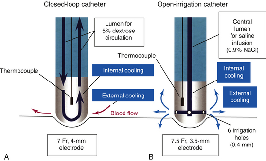
There are two methods of active electrode cooling by irrigation: internal and external (Fig. 7-6). With the internal (closed-loop) system (Chilli, Boston Scientific, Natick, Mass.), cooling of the ablation electrode is performed by circulating fluid within the electrode.18 In contrast, with the external (open-loop) system (Celsius or Navistar ThermoCool, Biosense Webster, Inc., Diamond Bar, Calif.; and Therapy Cool Path, St. Jude Medical, Inc., St. Paul, Minn.), electrode cooling is performed by flushing saline through openings in the porous-tipped electrode (showerhead-type system).18 Another cooling system is sheath-based open irrigation, which uses a long sheath around the ablation catheter for open irrigation. The latter system was found to provide the best results, but this type of catheter tip cooling is not clinically available.
Active electrode cooling by irrigation can produce higher tissue temperatures and create larger lesions, compared with standard RF ablation catheters, because of a reduction in overheating at the tissue-electrode interface, even at sites with low blood flow. This allows the delivery of higher amounts of RF power for a longer duration to create relatively large lesions with greater depth but without the risk of coagulum and char formation. Unlike with standard RF ablation, the area of maximum temperature with cooled ablation is within the myocardium, rather than at the electrode-myocardial interface. Higher power results in greater depth of volume heating, but if the ablation is power limited, power dissipation into the circulating blood pool can actually result in decreased lesion depth (Fig. 7-7).18 Compared with large-tip catheters, active cooling has been shown to produce equivalent lesions with energy delivery via smaller electrodes, with less dependence on catheter tip orientation and extrinsic cooling, whereas larger electrodes have significant variability in their electrode-tissue interface, depending on catheter orientation (see Fig. 7-7). For the nonirrigated catheter, greater lesion volumes are observed with a horizontal orientation of the RF electrode compared with a vertical orientation. In contrast, for irrigated catheters, lesion volume increased with a perpendicular electrode orientation compared with the horizontal orientation.10
Lesion depth seems to be similar between closed-loop and open-irrigation electrodes. However, open irrigation appears to be more effective in cooling the electrode-tissue interface, as reflected by lower interface temperature, lower incidence of thrombus, and smaller lesion diameter at the surface (with the maximum diameter produced deeper in the tissue). These differences between the two electrodes are greater in low blood flow, presumably because the flow of saline irrigation out of the electrode provides additional cooling of the electrode-tissue interface (external cooling). Ablation with the closed-loop electrode, with irrigation providing only internal cooling, in low blood flow frequently results in high electrode-tissue interface temperature (despite low electrode temperature) and thrombus formation.18
When maximum power and temperature parameters that did not result in increased rates of complications and any evidence of excessive heating (including popping, boiling, or impedance rise) for each catheter type were selected, closed-irrigation catheters resulted in slightly larger lesion volumes and greater lesion depths than the open-irrigation catheters. Both cooled catheters fared better than the standard 4-mm-tip and large 10-mm-tip catheters with larger lesions achieved within the range of safe energy delivery.19
Monitoring Radiofrequency Energy Delivery
There is a significant discrepancy between monitored electrode temperature and tissue temperature during cooled RF ablation.6,8 The thermal effects on the electrode temperature are dependent on electrode heating from the tissue, internal cooling by the irrigation fluid, and external cooling from blood flow or open irrigation. With high irrigation flow rates, catheter tip temperature is not representative of tissue temperature, and therefore feedback cannot be used to guide power output. The difference between the electrode temperature and interface temperature is greater with the closed-loop electrode than with the open-irrigation electrode. The discrepancy is likely to be increased in areas of high blood flow, by increasing the irrigation flow rate, or by cooling the irrigant. Saline-irrigated catheters cause peak tissue heating several millimeters from the electrode-tissue interface. Because maximum tissue heating does not occur at the electrode-tissue interface, the value of temperature and impedance monitoring is limited with this type of catheter.
Therefore, it has been challenging to monitor lesion formation and optimize power delivery during cooled RF ablation.6 Appropriate energy titration is important to allow greater power application and to produce large lesions while avoiding overheating of tissue with steam formation leading to pops. Moreover, the inability to assess tissue heating, and hence to titrate power to an objective endpoint, prevents the operator from determining whether unsuccessful applications are caused by inadequate mapping or inadequate heating.
Electrode-tissue contact and orientation and the cooling effect of blood flow around the electrode and within the tissue are not as easily adjusted, and they also influence tissue heating. However, several other factors can be potentially manipulated to adjust ablation with saline-irrigated catheters, including flow rate, irrigant temperature, and RF power and duration. The most easily controllable factors are the power and duration of RF application. Instead of increasing the power to achieve the desired effect, which increases the likelihood of crater formation, the duration may be increased. A moderate power of 20 to 35 W with a relatively long RF duration of 60 to 300 seconds should be considered to achieve relatively large lesions, with a limited risk of crater formation.6
The flow rate of the irrigant determines the degree of cooling. Faster flow rates likely allow greater power application without impedance rises, increase the difference between tissue and electrode temperature, and thereby potentially increase the risk of steam pops if temperature is used to guide ablation. With the internally irrigated ablation system, the approved flow rate is fixed at 36 mL/min and is not currently manipulated.6 With the externally irrigated ablation system, an irrigation flow rate of 10 to 17 mL/min during RF application (and 2 mL/min during all other times to maintain patency of the pores in the electrode) may be selected in a power-controlled mode with a delivered power of up to 30 W. The irrigation flow rate should be increased to 20 to 30 mL/min with delivery of more than 30 W, to avoid excessive heat development at the superficial tissue layers. Additionally, the temperature of the irrigant can potentially be manipulated. Cooling the irrigant can allow power delivery to be increased without coagulum formation. The cooled irrigant is warmed as it passes through the tubing to reach the catheter and through the length of the catheter. The impact of cooling the irrigant has not been well studied. In most studies, the irrigant that enters the catheter is at room temperature.
Several indicators of tissue heating may be monitored, including catheter tip temperature, EP effects of RF, and the use of ICE. As noted, with cooled RF, the discrepancy between measured electrode temperature and tissue temperature is greater than during standard RF ablation.8 Identification of microbubbles on ICE has been used as an indication of excessive tissue heating during ablation with nonirrigated and internally irrigated catheters. External irrigation, on the other hand, produces visible bubbles, precluding the use of this method.17,19
Evidence of tissue heating from an effect on recorded electrograms or the arrhythmia can be used to guide ablation energy.6 Interruption of tachycardia (VT, atrial flutter [AFL], supraventricular tachycardia) or block in conduction over a pathway (AVN or BT) during the process of ablation provides immediate feedback about the disruption of tissue integrity. Additionally, an increase in pacing threshold and a decrease in electrogram amplitude can indicate tissue damage. These factors, however, are not easily monitored during the RF application, particularly the change in pacing threshold. Moreover, the decrease in electrogram amplitude is often not visible during RF application because of superimposed electrical artifact.
With the internally irrigated system, the room temperature irrigant flowing at 36 mL/min typically cools the measured electrode temperature to 28° to 30°C. During RF application, the temperature increases; temperatures of 50°C can indicate that cooling is inadequate or has stopped, which warrants termination of RF application. The measured impedance typically decreases during cooled RF ablation by 5 to 10 Ω, in a manner similar to that observed during standard RF ablation.6
During open-irrigation RF ablation, initiation of irrigation results in a drop of electrode temperature by several degrees. Failure of electrode temperature to decrease indicates a lack of irrigant flow. When power delivery begins, catheter tip temperature should rise to 36° to 42°C (the presence of rising temperature, not the magnitude, reflects tissue heating). Temperatures higher than 40°C achieved with low power (less than 20 W) can indicate that the electrode is in a location with little or no cooling from the surrounding circulating blood, or that there is a failure of the catheter cooling system that requires attention. In contrast, the absence of any increase in tip temperature should raise the possibility of poor catheter contact.9
The optimal method for adjusting power during saline-irrigated RF ablation is not yet clearly defined, but some useful guidelines have emerged. The most commonly recommended approach is to perform ablation in a power-controlled mode, typically starting at 20 to 30 W and gradually increasing power to achieve evidence of tissue heating or damage. An impedance fall likely indicates tissue heating, similar to that observed with conventional RF. When catheter temperature is between 28° and 31°C, power can be ramped up, watching for a 5- to 10-Ω impedance fall. Measured electrode temperature will generally increase. A measured electrode temperature of 37° to 40°C is commonly achieved.
Temperatures exceeding 40° to 42°C with power greater than 30 W during open-irrigation RF ablation can be associated with a greater risk of steam pops and impedance rises, particularly during long RF applications, exceeding 60 seconds. Steam pops are often, but not always, audible. A sudden decrease in temperature, sudden catheter movement (as a consequence of the pop blowing the catheter out of position), and a sudden change in impedance are all potential indications that a pop has occurred. Whether the catheter is maintained in a stable position, as opposed to dragging it across the tissue, also likely influences tissue heating. High power can be applied continuously during dragging with little risk of excessive heating, although the duration of time to spend at each site to create an effective lesion may be difficult to ascertain.17 As a rule, the lowest effective power setting, shortest duration, and fewest applications should be employed whenever possible.9
Clinical Applications of Cooled Radiofrequency Ablation
Cooled tip catheters are preferred (1) for long linear ablations (in the right or left atrium) and complex atrial arrhythmias (AFL or AF), (2) when there is a high probability of encountering thick or trabeculated tissue, (3) for specific areas with low local blood flow (including the coronary sinus [CS], particularly CS aneurysms, and pericardial space), (4) when ablating in the arterial circulation (to minimize the likelihood of arterial thromboembolism), and (5) for targets resistant to previous conventional ablation (focal tachycardias or BTs). Clinical trials have found irrigated tip catheters to be more effective than and as safe as conventional catheters for AFL ablation, thus facilitating the rapid achievement of bidirectional isthmus block. Irrigated tip catheters also were found to be safe and effective in eliminating BT conduction resistant to conventional catheters, irrespective of the location, and they have been successfully used for PV isolation for treatment of AF. Irrigated tip catheters also offer an advantage over conventional RF catheters in the case of scar-related VTs, by facilitating creation of larger and deeper lesions that can help eliminate intramyocardial or subepicardial reentrant pathways necessary for the VT circuit.9,17,20
Internally cooled RF ablation is an attractive choice for use in pericardial ablation because no fluid is infused, and one need not worry about monitoring pericardial fluid throughout the ablation procedure, although drainage of irrigant during open-irrigation RF ablation can be managed in this setting.9
Power levels typically used during open-irrigation ablation depend on the site of ablation: 25 to 30 W in the left and right atrial free wall, 35 to 40 W for cavotricuspid isthmus and mitral isthmus ablation, 50 W in the left ventricle, and 20 W in the CS. At low power levels, the irrigation flow rate may be set lower than at higher levels; 17 mL/min is used for power output lower than 30 W, whereas 30 mL/min is used for power output of 30 to 50 W. Using a lower irrigation flow rate (10 mL/min) in the left atrium can help maintain some temperature feedback, with a cutoff temperature of 43°C. Lesion formation is monitored via attenuation of the local unipolar electrogram. Because of the very limited or absent temperature feedback, tissue overheating (pops) is a potential risk, especially in thin-walled chambers. The temperature is usually set at 40° to 45°C. If the temperature at the tip is lower than 40°C, the flow rate may be reduced. If the desired power is not met because the target temperature is reached at a lower power, the irrigation flow rate may be increased to a maximum of 60 mL/min.4 Parameters for epicardial ablation are similar to those used for endocardial ablation.17
Potential Risks of Cooled Radiofrequency Ablation
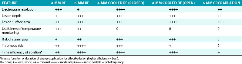
Although creation of larger ablation lesions can improve the efficacy of ablation for some patients, particularly when the targeted arrhythmia originates deep to the endocardium and when large areas require ablation, it is associated with increased risk of damage to tissue outside the target region (Table 7-1).
Higher power can be used with convective cooling, but higher power can cause superheating within the tissue (with subendocardial tissue temperatures exceeding 100°C) that can result in boiling of any liquids under the electrode. Consequently, evaporation and rapid steam expansion can occur intramurally, and a gas bubble can develop in the tissue under the electrode. Continuous application of RF energy causes the bubble to expand and its pressure to increase, which can lead to eruption of the gas bubble (causing a popping sound) through the path with the least mechanical resistance that leaves behind a gaping hole (the so-called pop lesion). This often occurs toward the heat-damaged endocardial surface (crater formation) or, more rarely, across the myocardial wall (myocardial rupture).18
Steam pops are often associated with a sudden (although small, less than 10 Ω) impedance rise and a sudden drop in electrode temperature. The consequence of a steam pop depends on the area of the heart being ablated. The risk of cardiac perforation is low in areas of dense ventricular scar. The risk of perforation and cardiac tamponade is likely to be higher for ablation in the thin-walled right ventricular outflow tract and in the atria. Therefore, it may be reasonable to take a more conservative approach to power application in these areas. Electrode orientation also seems to affect the significance of pops; pops that occur when the electrode tip is perpendicular to the tissue can be more likely to cause cardiac perforation than those that occur when the electrode is lying horizontally on the tissue. Therefore, one should try to avoid perpendicular (high-pressure) tissue contact, especially at higher power levels.17 RF applications with steam pops have a greater decrease in impedance and occur at a higher maximum RF power than applications without pops. Because of the considerable overlap of impedance changes in lesions with and without steam pops, it is not possible to advocate a general limit for impedance decrease for all RF lesions. However, when ablation is performed in areas at risk for perforation (i.e., especially in thin-walled structures), reducing power to achieve an impedance decrease of less than 18 Ω is a reasonable strategy to reduce the chance of a pop.20
Although increasing power delivery and convective cooling can create large lesions, lesion production is somewhat difficult to control. Surface cooling does reduce the risk of boiling and coagulum formation. However, it does not allow the temperature at the tip to be monitored, and thus some feedback about lesion formation is lost.18
These concerns can be more pronounced with internal cooling as compared with open irrigation. Open irrigation cools the electrode and its direct environment, blood, and tissue surface. In contrast, with internal cooling, the main parameter affected by cooling is the temperature of the electrode. There can be minimal cooling of the direct electrode-tissue interface, but only at the true contact site between metal and tissue. Blood flow around the electrode makes it highly unlikely that there will be any noticeable cooling of the tissue surface at a distance of a few millimeters from the contact site. Consequently, one would not expect much effect of internal electrode cooling on the surface area or depth of the lesion. Electrode cooling does, however, enable larger lesions (at higher power levels) because the ablation process is no longer limited by electrode temperature rise. This can also be dangerous; in cases with good tissue contact, power delivery to the tissue can be much higher than average. With standard electrodes, this situation is signaled by an excessive electrode temperature rise, but without this warning, tissue overheating can occur. Blood clots can also be formed, but they do not adhere to a cool electrode and do not cause an impedance rise.4
With open-irrigation catheters, extensive ablation often performed for AF and scar-related VT can result in substantial saline administration. Therefore, management of the patient’s volume status before, during, and after the procedure is crucial. This is also important during epicardial ablation, in which an obligatory fluid volume enters the pericardial sac and, if not intermittently or continuously evacuated, gradually results in cardiac tamponade. This complication can be prevented by having the side port of the introducer sheath attached to a suction bottle or gravity drain or by intermittent aspiration of accumulated fluid. Internal irrigation, on the other hand, has the advantages that no fluid is infused into the vasculature or pericardial space, and there is no possibility of embolization from the irrigation system.17
Cryoablation
Biophysics of Cryothermal Energy
Cryoablation uses a steerable catheter and a dedicated console, which are connected by a coaxial cable used to deliver fluid nitrous oxide to the catheter and to remove the gas from the catheter separately.21 A tank of fluid nitrous oxide is located inside the console; the gas removed from the catheter to the console is evacuated through a scavenging hose into the vacuum line of the EP laboratory. The system has several sensors to avoid inadvertent leaks of nitrous oxide into the patient body and to check connections of the different cables to the console.
Cryoablation catheters have a terminal segment whose temperature can be lowered to –75°C or less by delivery of precooled compressed liquid refrigerant (nitrous oxide argon) across a sudden luminal widening at the end of the catheters’ refrigerant circulation system (Fig. 7-8). Decompression and expansion of the refrigerant (liquid to gas phase change) achieve cooling based on the Joule-Thompson effect.22
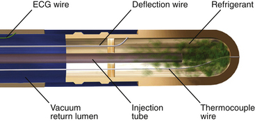
FIGURE 7-8 Schematic diagram demonstrating the CryoCath Freezor cryocatheter internal design.
(Courtesy of CryoCath Technologies, Montreal, Canada.)
The effect produced by cryothermal ablation is secondary to tissue freezing, the result of a temperature gradient occurring at the electrode-tissue interface (i.e., local heat absorption by the cooled catheter tip). It greatly depends on the minimum temperature reached, the duration of energy application, and the temperature time constant. The temperature time constant indicates the course of the descent of temperature to the target temperature, and a shorter value (expressed in seconds) identifies a more effective application. Important modulatory variables that can affect tissue damage produced by cryoablation include firmness of the catheter-tissue contact, tip temperature, freeze duration, and blood flow.22
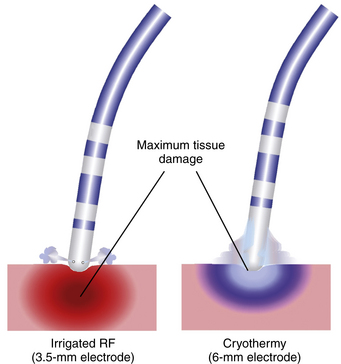
At the electrode-tissue interface, the coldest area is the one adjacent to the catheter tip, where functional effects of energy delivery are observed earlier (Fig. 7-9). Conversely, the less cooled area is the one at the periphery of the cryolesion, whose dimensions can also vary according to the duration of freezing. Because of limited cooling of the outer limit of the lesion (both in time and temperature), this region is less likely to suffer irreversible damage. As a consequence, the effects obtained late during cryothermal energy application are likely to be reversible early on rewarming, and, therefore, any expected functional modification induced by cryoenergy should occur early (usually within the first 30 seconds of the application) to obtain a successful and permanent ablation of a given arrhythmogenic substrate.22
Currently, two different systems of catheter cryoablation are available for clinical and experimental use: the CryoCath system (CryoCath Technologies, a division of Medtronic, Inc., Minneapolis, Minn.) and the CryoCor system (CryoCor, San Diego, Calif.). CryoCath uses 7 or 9 Fr steerable catheters with 4-, 6-, or 8-mm-long-tip electrodes. The ablation catheter is connected to a dedicated console, which has two algorithms available. The first is for cryomapping with a slow decrease of temperature to –30°C for up to 80 seconds, and the second is for cryoablation with a faster decrease of temperature to –75°C for up to 480 seconds. Additionally, the target temperature can be manually preset on the console at any value between –30° and –75°C. The CryoCor system has 10 Fr steerable catheters with 6.5- or 10-mm-long-tip electrodes. The console has a built-in closed-loop precooler for the fluid nitrous oxide, whose flow at the catheter tip is adjusted during the application to maintain a temperature of –80°C.22
An expandable cryoablation balloon catheter (Arctic Front, CryoCath Technologies, Inc.), 18 to 30 mm in diameter, has been specifically designed for PV isolation. The cryoballoon is deployed at the ostium of targeted PVs, and cryoenergy is delivered over the occluding balloon system to create circumferential lesions around the PV ostium. This design helps limit the convective warming effects of the high blood flow at the PV ostium, which can limit lesion size and ablation efficacy, as well as shorten the lengthy procedure times required for circumferential point-by-point cryoablation around the PV ostia with the standard steerable cryocatheters.23–25
Pathophysiology of Lesion Formation by Cryoablation
Mechanism of Tissue Injury
The mechanisms underlying lesion formation by cryoenergy are twofold: direct cell injury and vascular-mediated tissue injury. The mechanisms of cellular death associated with tissue freezing involve immediate cellular effects, as well as late effects that determine the lesion produced.22
Direct Cell Injury
Extracellular Ice (Solution Effect Injury)
Direct cellular injury results from ice formation. Ice forms only extracellularly when the tissue is cooled to mild temperatures (0° to –20°C) and results in hypertonic stress (the extracellular environment becomes hyperosmotic). The consequent shift of water from the intracellular to the extracellular space ultimately causes cell shrinkage and damage to the plasma membrane cellular constituents. These effects are reversible when rewarming is achieved within a short period (30 to 60 seconds). However, extended periods of extracellular freezing result in cellular death, and rewarming then results in cellular swelling sufficient to disrupt cellular membranes.21
Intracellular Ice
When the tissue is cooled to –40°C or lower, especially if it is cooled at rapid rates, ice forms extracellularly and intracellularly. Intracellular ice results in major and irreversible disruption of organelles, with cellular death.21 Although ice crystals do not characteristically destroy cell membranes, they compress and deform nuclei and cytoplasmic components. Mitochondria are particularly sensitive to ice crystals and are the first structures to suffer irreversible damage. Furthermore, intracellular ice can propagate from one cell to another via intercellular channels, thus potentially resulting in lesion growth. Cellular injury, disruption of membranous organelles in particular, is importantly enhanced on cellular thawing; rewarming causes intracellular crystals to enlarge and fuse into larger masses that extend cellular destruction. Cellular injury can be extended by repeated freeze-thaw cycles. Final rewarming evokes an inflammation response to released cellular constituents and reperfusional hemorrhage, leading to tissue repair and eventual dense scarring.22 The size of ice crystals and their density depend on the proximity to the cryoenergy source, local tissue temperature achieved, rate of freezing, and surface area in contact with freezing temperatures.26,27
Vascular-Mediated Tissue Injury
Tissue freezing results in vasoconstriction, hypoperfusion, and ischemic necrosis.21 Subsequent tissue rewarming produces a hyperemic response with increased vascular permeability and edema formation. Endothelial disruption within the frozen tissue is also observed and results in platelet aggregation, microthrombi, and microcirculatory stagnation within the lesion. Cryolesions, however, are associated with substantially less degree of endothelial damage and overlying thrombus formation than standard RF lesions. Extensive surgical experience has shown that cryolesions result in dense homogeneous fibrosis, with a well-demarcated border zone. They are nonarrhythmogenic and preserve the underlying extracellular matrix and tensile strength.22
In the final phase of cryoinjury, replacement fibrosis and apoptosis of cells near the periphery of frozen tissue give rise to a mature lesion within weeks. Typically, these lesions are well circumscribed, with distinct borders, dense areas of fibrotic tissue, contraction band necrosis, and a conserved tissue matrix, including endothelial cell layers.26
Determinants of Lesion Size
During cryoablation, lesion size and tissue temperature are related to convective warming, electrode orientation, electrode contact pressure, electrode size, refrigerant flow rate, and electrode temperature.28 Lesion sizes during catheter cryoablation can be maximized by use of larger ablation electrodes with higher refrigerant delivery rates. A horizontal electrode orientation to the tissue and firm contact pressure also enhance lesion size. For a given electrode size, electrode temperature may be a poor predictor of tissue cooling and lesion size. In contrast to RF ablation, cryoablation in areas of high blood flow can result in limited tissue cooling and smaller lesion sizes because of convective warming. Conversely, cryoablation lesion size can be maximized in areas of low blood flow.22,28 The time to reach –80°C can predict cryoablation lesion size; cryoablation lesion volume increases as the time to reach –80°C decreases.29 The 6- and 8-mm electrode-tip cryocatheters produce ablation lesions of similar depth that are more than two- and threefold larger than 4-mm catheters, respectively. Despite larger lesions, endothelial cell layers remain intact and devoid of thrombosis. Surface areas and volumes may be particularly sensitive to catheter tip-to-tissue contact angles with larger electrodes. As such, particular attention in catheter orientation is required with 8-mm electrode-tip cryocatheters to produce desired lesions.27
Technical Aspects of Cryoablation
The intervention is often performed in two steps. First, “cryomaps” are obtained by moderate reversible cooling of tissue (electrode-tissue interface temperature approximately –28° to –32°C). Second, cryoablation cools the selected cryomapped pathways to much lower temperatures (electrode-tissue interface temperature lower than –68°C) and produces ice formation inside and outside of cells, a mechanism of irreversible cellular injury.22
Cryomapping
Cryomapping is designed to verify that ablation at the chosen site will have the desired effect and to ensure the absence of complications (i.e., to localize electric pathways to be destroyed or spared). This procedure is generally performed using various pacing protocols that can be performed during cryomapping (or ice mapping) at –32°C. At this temperature, the lesion is reversible (for up to 60 seconds), and the catheter is stuck to the adjacent frozen tissue because of the presence of an ice ball that includes the tip of the catheter (cryoadherence). This permits programmed electrical stimulation to test the functionality of a potential ablation target during ongoing ablation and prior to permanent destruction. It also allows ablation to be performed during tachycardia without the risk of catheter dislodgment on termination of the tachycardia.
In the cryomapping mode, the temperature is not allowed to drop to less than –30°C, and the time of application is limited to 60 seconds. Formation of an ice ball at the catheter tip and adherence to the underlying myocardium are signaled by the appearance of electrical noise recorded from the ablation catheter’s distal bipole. Once an ice ball is formed, programmed stimulation is repeated to verify achievement of the desired effect. If cryomapping does not yield the desired result within 20 to 30 seconds or results in unintended effect (e.g., AV conduction delay or block), cryomapping is interrupted, to allow the catheter to thaw and become dislodged from the tissue. After a few seconds, the catheter may be moved to a different site and cryomapping repeated.22
Cryoablation
When sites of successful cryomapping are identified by demonstrating the desired effect with no adverse effects, the cryoablation mode is activated, in which a target temperature lower than –75°C is sought (a temperature of –75° to –80°C is generally achieved). The application is then continued for 4 to 8 minutes, thus creating an irreversible lesion. If the catheter tip is in close contact with the endocardium, a prompt drop in catheter tip temperature should be observed as soon as the cryoablation mode is activated. A slow decline in catheter tip temperature or a very high flow rate of refrigerant during ablation suggests poor electrode-tissue contact. In such cases, cryoablation is interrupted, and the catheter is repositioned.22
Advantages of Cryoablation
The use of cryoablation in the EP laboratory provides some distinct advantages not seen with conventional RF ablation. The slow development of the cryolesion (approximately 240 seconds), although time-consuming, enables the creation of reversible lesions and modulation of lesion formation in critical areas. As noted, cryomapping allows functional assessment of a putative ablation site during ongoing ablation and prior to permanent destruction. This offers a safety advantage when ablation is performed close to critical structures such as the AVN or His bundle (HB).30
Compared with standard RF lesions, cryolesions are associated with a substantially lower degree of endothelial disruption, less platelet activation, and lower thrombogenic tendency. Therefore, the risk of coagulum formation, charring, and steam popping is less than with RF ablation (see Table 7-1). Furthermore, cryoablation results in dense homogeneous fibrotic lesions with a well-demarcated border zone and does not cause collagen denaturation or contracture related to hyperthermic effects. Therefore, cryothermal energy application in close proximity to the coronary arteries (e.g., during epicardial ablation) or in venous vessels (CS, middle cardiac vein, and PVs) does not result in damage, perforation, or chronic stenosis of their lumen.22,30
Cryothermal energy application is characterized by the absence of pain perception in nonsedated patients. In fact, cryoablation can be performed without analgesia. Occasionally, a light sense of cold or headache is perceived as minor discomfort. This characteristic can be particularly useful in younger and pediatric patients.22
Clinical Applications of Cryoablation
As noted, catheter-based cryoablation can have specific advantages over RF catheter ablation, including greater safety as a result of greater catheter stability, reduced risk of systemic embolization, low propensity for thrombus formation and endothelial disruption, and preservation of ultrastructural tissue integrity. As a result, cryoablation has quickly been adapted for specific arrhythmogenic substrates in which RF has specific limitations that can potentially be overcome by cryothermy.30
It is unlikely that cryoablation will replace standard RF ablation in unselected cases. Nevertheless, for the previously mentioned peculiarities, cryothermal ablation has proven effective and safe for the ablation of arrhythmogenic substrates close to the normal conduction pathways. It has become the first-choice method to ablate superoparaseptal and midseptal BTs and difficult cases of AVNRT because of its widely demonstrated safety profile. As the technology evolves and further iterations of the catheter proceed, the role for this technology is likely to grow.31
Atrioventricular Nodal Reentrant Tachycardia
So far, slow pathway ablation for AVNRT by cryothermal energy represents the larger experience in the clinical application of this technology.21,32 Previously published reports with cryoablation of AVNRT in pediatric patients demonstrated procedural success rates of 83% to 97% and recurrence rates ranging from 0% to 20%. Although the use of bonus cryoapplications to consolidate the acutely successful cryoablation and the availability of larger tip cryocatheters (6 to 8 mm and 6 mm versus 4 mm) to create larger lesions have been associated with fewer recurrences on long-term follow-up without compromising safety, the overall procedural success rates have remained consistently lower than those (95% to 99%) with RF ablation.31,33–36
According to current data, cryothermal energy is a valuable and useful alternative to RF energy to treat patients with AVNRT. The absence of permanent inadvertent damage of AV conduction makes this new technology particularly useful for patients with difficult anatomy, after an unsuccessful prior standard ablation procedure, in pediatric patients, and in patients in whom even the small risk of AV block associated with RF ablation is considered unacceptable. Cryoablation can be of particular advantage in several situations, including posterior displacement of the fast pathway or AVN, a small space in the triangle of Koch between the HB and the CS ostium, and the need for ablation to be performed in the midseptum. However, given the high success rate and low risk of RF slow pathway ablation, it can be difficult to demonstrate a clinical advantage of cryoablation over RF ablation in unselected AVNRT cases.22
Bypass Tracts
Cryothermal ablation of BTs in the superoparaseptal and midseptal areas, both at high risk of complete permanent AV block when standard RF energy is applied, is highly safe and successful (Fig. 7-10).32 Cryoablation can also be successfully and safely used to ablate selected cases of epicardial left-sided BTs within the CS, well beyond the middle cardiac vein, once attempts using the transseptal and transaortic approaches have failed.21 However, the experience with cryoablation in unselected BTs is more limited and less satisfactory; this can be related to multiple factors, including the learning curve and the smaller size of the lesion produced by cryoablation. In addition, all the peculiarities of cryothermal energy, which are optimal for septal ablation, are less important or even useless for ablation of BTs located elsewhere.21
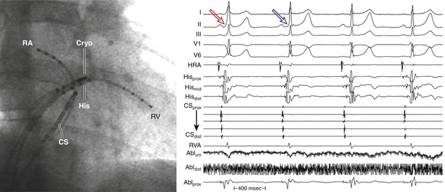
In more recent series, the short-term success rate of cryoablation of BTs in the superoparaseptal and midseptal regions exceeded 90%; however, resumption of BT conduction with recurrence of symptoms can occur in up to 20% of patients, and overall success rates have been lower than those of AVNRT cryoablation. It is, however, important to note that alternatives for elimination of some of those BTs are limited by a prohibitive risk of AV block with RF ablation. Although transient modifications of the normal AVN conduction pathways can be observed during cooling and right bundle branch block has occurred on occasion, no permanent modifications have been observed, and inadvertent AV block has yet to be reported. In fact, immediate discontinuation of cryothermal energy application at any temperature on observation of modification of conduction over normal pathways results in return to baseline condition soon after discontinuation.30
Focal Atrial Tachycardia
Occasionally, successful cryoablation of focal AT has been reported. Its safety has also been confirmed for ablation of atrial foci located close to the AVN. Cryoenergy can also be particularly valuable in ablating focal sources within venous structures.30
Typical Atrial Flutter
Complete cavotricuspid isthmus block can be achieved by cryothermal ablation. In addition to the safety advantages of cryoenergy discussed earlier, cryolesions are limited by convective warming effects of blood flow, which reduces the risk of damage to nearby coronary arteries. Another advantage of using cryothermal energy for the ablation of typical AFL is the absence of pain perception related to energy application.30,37 Previous studies reported cryoablation of the cavotricuspid isthmus for typical AFL with short-term and long-term success comparable to results with RF ablation. However, a more recent prospective randomized study comparing RF and cryothermal energy for ablation of typical AFL suggested that lesion durability from cryoablation was significantly inferior to that of RF ablation. Although acutely successful ablation rates in the cryoablation group were comparable to those for RF ablation (89% versus 91%), persistence of bidirectional isthmus block in patients treated with cryoablation reinvestigated 3 months following ablation was inferior to that in patients treated with RF ablation, as evidenced by the higher recurrence rate of symptomatic, ECG-documented AFL (10.9% versus 0%), and higher asymptomatic conduction recurrence rates (23.4% versus 15%). Additionally, compared with RF ablation, cryoablation is associated with significantly longer procedure times. This is driven mainly by differences in ablation duration, which can be attributed to the longer duration of each cryoablation (4 minutes) compared with RF ablation (up to 60 seconds).22,38
Pulmonary Vein Isolation
For the characteristics mentioned earlier, cryothermal energy ablation can be considered an ideal and safer energy source for PV isolation, and the incidence of PV stenosis and thromboembolic events is expected to be dramatically reduced compared with RF ablation. Additionally, cryoablation has never been associated with atrioesophageal fistula.39,40 On the other hand, cryothermal injury is sensitive to surrounding thermal conditions. The high flow of the PVs can present a considerable heat load to cryothermal technologies, which can limit the size and depth of the lesion produced by cryothermal energy at the ostium of the PV. Furthermore, cryoablation of PVs by standard steerable catheters is very time-consuming, considering that one single ablation point takes about 4 minutes.
A new catheter design for circumferential ostial ablation of the PVs has been developed, with the option of deploying an inflatable balloon in the PVs to reduce the heat load related to blood flow (Fig. 7-11).21,39 The cryoballoon is deployed at the ostium of targeted PVs, and cryoenergy is delivered over the occluding balloon system to create circumferential lesions around the PV ostium. The clinical short-term and long-term success rates of this approach are acceptable; however, the risk of phrenic nerve injury is relatively high because of ablation in the region of the right superior PV. To date, thromboembolism or PV stenosis has yet to be reported.23–25,41–45
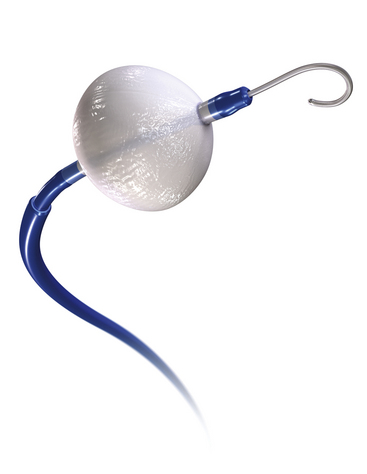
Ventricular Tachycardia
Data regarding cryoablation for VT remain scant. Small reports described feasibility and success of cryoenergy for ablation of outflow tract VT. Additionally, cryothermal energy can be of potential advantage in percutaneous subxiphoid epicardial ablation of VT because of less potential damage to the epicardial coronary arteries. The reduced heat load in the pericardial space related to the absence of blood flow limits RF energy delivery but can be to the advantage of cryoablation, with the possibility of producing larger transmural lesions.22
Microwave Ablation
Biophysics of Microwave Energy
Microwaves are the portion of the electromagnetic spectrum between 0.3 and 300 GHz. For the ablation of cardiac arrhythmias, microwave energy has been used at frequencies of 0.915 and 2.450 GHz. Similar to RF, microwave energy produces thermal cell necrosis. However, in contrast to heating by electrical resistance as observed during RF ablation, the mechanism of heating from a high-frequency microwave energy source is dielectrics. Dielectric heating occurs when high-frequency electromagnetic radiation stimulates the oscillation of dipolar molecules (e.g., water molecules) in the surrounding medium at a very high speed, thereby converting electromagnetic energy into kinetic energy. This high-speed vibration favors friction between water molecules within the myocardial wall that results in an increase of myocardial tissue heat.1 This mode of heating lends microwave ablation the potential for a greater depth of volume heating than RF ablation and should theoretically result in a larger lesion size.46
The effectiveness of microwave ablation depends on the radiating ability of the microwave antenna that directs the electric field and determines the amount transmitted into the myocardium, which is critical for heating. An end-firing monopolar antenna has been used to produce lesions at depths of 1 cm without disruption of the endocardium in porcine ventricles. The depth of these lesions increased exponentially over time as compared with standard nonirrigated RF energy, which had minimal lesion expansion after 60 seconds of ablation.1 To concentrate more of the energy distribution near the electrode tip, circularly polarized coil antennas have been developed. Other configurations of the microwave antenna include helical, dipole, and whip designs; these have a large effect on the magnetic field created. However, many of these catheters are still under clinical investigation.
Pathophysiology of Lesion Formation by Microwave Ablation
Microwave energy produces thermal cell necrosis and transmural damage, with foci of coagulation necrosis of myocytes in the central part of the lesion. Hyperthermia (more than 56°C) causes protein denaturation and changes in myocardial cellular EP properties resulting from movement of mobile ions within the aqueous biological medium and altering membrane permeability. The acute myocyte changes include architectural disarray, loss of contractile filaments, and focal interruption of the plasma membrane, which are signs of irreversible injury. Additionally, occlusion of the lumen of the small intramyocardial vessels and severe disruption of endothelial and adventitial layers are observed.46 Carbonization does not occur on tissue surfaces because of the good penetration of microwave energy. Fibrotic tissue eventually replaces the necrotic muscle, which typically becomes sharply demarcated from normal myocardium.46
Although microwave ablation in theory should be less likely than RF to induce surface overheating, in vivo studies found that a higher targeted temperature of 90°C resulted in a surface temperature of more than 70°C and was associated with some tissue surface charring when compared with lower temperatures. Therefore, the use of the temperature-controlled mode of microwave energy delivery to limit the targeted temperature to 80°C may prevent tissue overheating and reduce the risk of tissue charring. It should be noted that no coagulation formation and no popping were observed during any of the microwave ablations performed.47,48
In contrast to RF energy, in which lesion expansion is maximal after 60 seconds, microwave lesion size continues to increase after 300 seconds of energy application. As compared with conventional 4-mm-tip RF ablation, microwave ablation creates a similar lesion depth and width. Lesion length created by a 10-mm antenna is comparable to that created by 8-mm-tip RF ablation. However, because of the lack of physical limitations on the length of the microwave antenna that can be made, microwave ablation may be more advantageous in creating long linear lesions by using longer antenna. Nevertheless, a parallel antenna orientation is needed for optimal energy delivery because the growth in lesion sizes is limited beyond the energy field as a result of the finite radial energy distribution of the microwave ablation antenna. Furthermore, the lesion depth created with an 8-mm-tip or saline-irrigated electrode catheter appears to be larger than the lesion depth created by microwave ablation. However, direct comparisons among these different ablation technologies are not available.47,48
Clinical Applications of Microwave Ablation
Microwave ablation can be a promising technique that is potentially capable of treating a wide range of ventricular and supraventricular arrhythmias. The physics of the microwave energy source can be particularly useful for transmural ablation lesions of atrial tissue, as well as the treatment of tachyarrhythmias arising from deep foci of ventricular myocardium.46
Microwave can potentially overcome several limitations of RF energy for linear ablation. In contrast to resistive heating produced by RF, microwave generates frictional heat by inducing oscillation of dipoles in a medium such as water. Tissue with higher water content, such as cardiac tissue, allows better energy transfer during the propagation of microwave energy deep into the tissue. Therefore, microwave energy is capable of creating deeper lesions, to penetrate scar tissue and to reduce surface heating with less endocardial disruption or coagulation formation. Furthermore, delivery of microwave energy is not limited by electrode size as in RF, and microwave ablation can be applied over a larger surface by modifying antenna size and shape. Another hypothetical advantage of microwave energy is that it provides sufficient lesions, independent of contact. However, experimental data have shown that penetration of electromagnetic fields into tissue declines exponentially, and the decline is steep when using frequencies in the microwave range; therefore, distance is still an important consideration. Nevertheless, this theoretical advantage can potentially improve the versatility of microwave ablation, especially in areas where muscular ridges and valleys may pose problems for conventional RF ablation.1,49
Currently, microwave ablation has been increasingly used intraoperatively (epicardially or endocardially) during surgical maze procedures. The ability to make microwave antennas into flexible linear applicators and place them parallel to the endocardium by means of clamps has increased the effectiveness of microwave as a tool in open-chest surgery and in minimally invasive surgery.50,51
The development and manufacture of antennae for delivery of microwave energy is technically more complex than for RF electrodes because the efficacy of microwave energy transmission depends mainly on its delivery apparatus. As a result, microwave antennae were previously bulky and were limited to surgical use. Developments in the catheter-based microwave system may allow the transvenous delivery of microwave energy for endocardial ablation. Only a few case reports have described the successful use of transvenous catheter microwave ablation of the AV junction and cavotricuspid isthmus.47,52,53
Currently, only one transvenous microwave catheter system (MedWaves, San Diego, Calif.) is available for investigational use. This system includes a deflectable, 10 Fr catheter with 10-mm or 20-mm helical coil antenna with temperature monitoring, bipolar electrode recording, and a generator delivering microwave at 900 to 930 MHz. Microwave energy is delivered by using a temperature-controlled mode in which the generator automatically adjusts the power output to maintain the targeted temperature of the temperature sensor inside the antenna. For ablation of typical AFL, linear lesions are created with a point-by-point technique with gradual pullback of the microwave catheter across the cavotricuspid isthmus. Interestingly, microwave causes no perception of pain during ablation of the cavotricuspid isthmus with energy delivery in the inferior vena cava region.49,53
Clinical studies on the use of transvenous catheter microwave ablation for AF and AFL ablation are currently under way to investigate the safety and feasibility of this technique.52,53
Ultrasound Energy
Biophysics of Ultrasound Energy
Sound is a propagation of cyclical (oscillatory) displacements of atoms and molecules around their average position in the direction of propagation. When the cyclical events occur at frequencies of more than 20,000 Hz (i.e., higher than the average threshold of the human hearing), the sound is defined as ultrasound.1,52
Ultrasound energy transmission is subject to attenuation with distance and medium, especially with air. The amount of ultrasound energy transferred to tissue is proportional to the intensity of the wave and the absorption coefficient of the tissue. Because of this property, ultrasound ablation does not require direct contact with the myocardium, in contrast to RF ablation. Ultrasound energy decreases proportionally with the distance (1/r), whereas RF ablation electrical conduction decreases with the square of the distance (1/r2). This feature allows ultrasound energy to create deeper and transmural lesions. The duration of application and acoustic power used have a direct relationship with the lesion depth.52
Pathophysiology of Lesion Formation by Ultrasound Energy
Tissue injury caused by ultrasound is mediated by two mechanisms: thermal and mechanical energy. Ultrasound waves can propagate through living tissue and fluids without causing any harm to the cells. However, by focusing highly energetic ultrasound waves (high-intensity focused ultrasound [HIFU]) to a well-defined volume, local heating (achieving a tissue temperature of 65° to 100°C) occurs and causes rapid tissue necrosis by coagulative necrosis. Thermal energy results when the energy transported by an ultrasound beam becomes attenuated as it propagates through viscous (viscoelastic) media, such as human soft tissue. The attenuation partly represents conversion of ultrasound energy into heat. Another mechanism by which HIFU destroys tissue is mechanical energy, which results from pressure waves (sound waves) propagating in gas-containing tissues as they cyclically expand (explode) and shrink (implode) microbubbles in the tissue (i.e., oscillation and collapse of gas microbubbles), a process known as microcavitation. This process of vibration of cellular structures causes local hyperthermia and mechanical stress by bubble formation because of rapid changes in local pressure, thus leading to cell death.1
Previous studies showed that rapid, focused absorption of HIFU energy in noncardiac tissue produced a steep tissue temperature gradient (2° to 5°C/sec) between the focus and the surrounding tissue, thus allowing for the production of sharply demarcated lesions and reducing collateral damage. However, a more recent study using HIFU for PV isolation in canine hearts found that HIFU produced a dual temperature profile, probably because of immediate direct acoustic heating and subsequent conductive heating. Additionally, the region of direct acoustic heating with HIFU energy in vivo was largely predictable from the distance of the target tissue to the HIFU balloon surface; actual tissue temperatures exceeding 50°C (the temperature at which permanent tissue damage is supposed to occur) were focused within a 7-mm width and 7.5-mm depth around the HIFU exit site (significantly larger than the 2- to 3-mm area of resistive heating observed with RF energy). However, the actual distribution of tissue temperatures during lesion generation may be affected by other factors, such as the following: blood circulation; location of different tissue thicknesses within the atrium, venoatrial junction, or PV; or energy attenuation at various interfaces between the target tissue and the energy source.54
HIFU lesion depth increases with longer duration of energy delivery from 15 to 60 seconds, and there is a linear relationship between increasing power and depth of lesions.1 HIFU applications were found to achieve transmural lesions and PV isolation. However, although this can translate into increased effectiveness of ablation, it also can potentially lead to collateral damage, namely to the phrenic nerve and esophagus. HIFU ablation can produce damage to the phrenic nerve when it is located within 4 to 7 mm of HIFU exit.54
Clinical Applications of Ultrasound Energy
HIFU is an attractive alternative energy source. Because it can be focused at specific depths, ultrasound can be advantageous when considering epicardial ablation. The presence of epicardial fat makes the use of standard RF current difficult, both with catheter-based epicardial ablation and minimally invasive surgical ablation.1,55 Furthermore, the ability of ultrasound to be collimated through echolucent fluid medium (e.g., water, blood) makes it ideal for a balloon delivery system, which can potentially facilitate circumferential ablation at the PV orifice with a single energy delivery.1 Another potential advantage of ultrasound is that it does not rely on extensive heating on the vein surface. This can be of value in PV isolation procedures, to help prevent PV stenosis seen with RF ablation. Because HIFU is delivered at the beam convergence site rather than at the tissue surface, successful ablation is less dependent on absolute balloon-tissue contact than other balloon-based technologies. Furthermore, unlike other energy sources, HIFU can be deflected within the balloon to create a wide, focused zone of energy delivery outside the PV orifice, thereby mimicking current wide area circumferential ablative approaches. Currently, no HIFU catheters are available that can be used for linear (instead of circular) ablation.54,56–58
More recently, a forward-projecting HIFU balloon catheter (ProRhythm, Inc., Ronkonkoma, N.Y.) was developed for circumferential PV isolation outside the PV ostia (to limit the risk of PV stenosis). Radially emitted ultrasound is reflected from the back of the balloon, thus resulting in forward projection of ultrasound energy, with a focal point at the balloon-endocardial interface (Fig. 7-12). This system has two noncompliant balloons. A 9-MHz ultrasound crystal is located in the distal balloon filled with contrast and water. The proximal balloon, filled with carbon dioxide, forms a parabolic interface with the distal balloon to reflect the ultrasound energy in the forward direction, by focusing a 360-degree ring (sonicating ring) of ultrasound energy 2 to 6 mm in front of the distal balloon surface. The distal balloon has three sizes—24, 28, or 32 mm in diameter—producing sonicating rings of 20, 25, or 30 mm in diameter. The acoustic power of the system is 45 W for all three balloons, with negligible loss of power in the balloon. The distal balloon is irrigated with contrast and water at 20 mL/min during ablation to keep the balloon cool (lower than 42°C). The catheter has a central lumen used for insertion of a hexapolar, spiral mapping catheter (ProMap, ProRhythm, Inc.) for real-time assessment of PV potentials.59–61
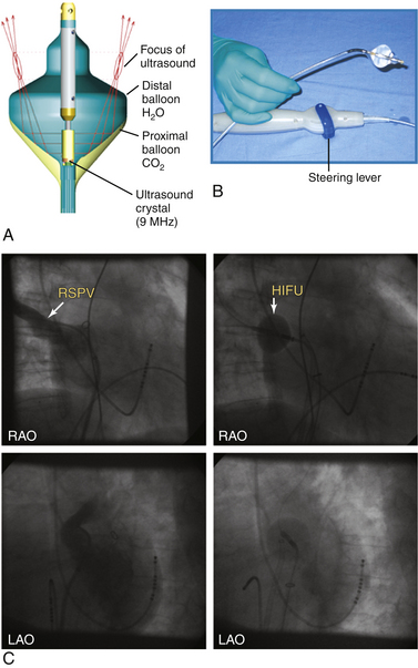
Clinical application of this system for PV isolation was evaluated and was shown to be feasible, but fatal esophageal injury was also observed.56–58 A study of 28 patients using an esophageal temperature–guided safety algorithm demonstrated that acute PV electrical isolation with HIFU ablation could be achieved in only 77% of PVs. Eight percent of PVs could not be isolated with HIFU as a result of excessive esophageal heating or balloon catheter dislodgment. In only 32% of patients, all PVs could be isolated using HIFU ablation only. Although power modulation did not negatively influence short-term success rates of PV electrical isolation, it also did not prevent esophageal temperature from exceeding levels higher than 40.0°C at the end of the ablation; elevated esophageal temperature prompting cessation of energy delivery occurred in 9% of PVs. Despite use of the safety algorithm and continuous phrenic nerve pacing, transient and persistent phrenic nerve palsy occurred in 14% and 7% of patients, respectively. Even worse, use of the safety algorithm could not prevent occurrence of esophageal thermal damage and lethal atrioesophageal fistula. PV isolation with HIFU has proven to be successful but is not yet safe for everyday clinical use. The problems of phrenic nerve palsy and atrioesophageal fistula occurrence remain unresolved. Still, the concept of the energy source and mode of energy delivery may be very interesting for future treatment of AF. With mean PV isolation times of less than 15 seconds and a high number of complications, it is evident that the present energy source is too powerful in some patients.59
Laser Energy
Biophysics of Microwave Energy
Light amplification by stimulated emission of radiation (laser) produces a monochromatic (narrow-frequency range) phase-coherent beam at a specific wavelength (Fig. 7-13). This beam can be directed for a specific duration and intensity, and as it penetrates the tissue, it is absorbed and scattered. The photothermal effect occurs with the absorption of photon energy, thus producing a vibrational excited state in molecules (chromophores). By absorbing this energy, the tissue is heated and a lesion is created (i.e., tissue injury is thermally mediated).1
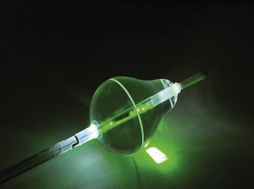
Laser energy can be delivered in a continuous or a pulsed mode. Laser energy is selectively absorbed by the tissues over several millimeters, and it decays exponentially as it passes through the tissue secondary to absorption and scatter, the extent of which depends on laser beam diameter and the optical properties of the tissue. Lesion size is determined by the extent of light diffusion and heat transport.1
Clinical Applications of Laser Energy
Early studies of laser ablation used a high-energy laser that carried a high risk of crater formation and endothelial damage. These studies focused on the intraoperative use of lasers in the ultraviolet and visible range (308- to 755-nm wavelength), and they appeared to show effectiveness of the lesions placed. Laser energy can also be delivered along the entire length of a linear diffuser, which provides uniform linear laser ablation and a superior transmural lesion when compared with previous end-firing optical delivery systems. The use of the linear diffuser in combination with lasers in the infrared or near-infrared wavelength (800 to 1100 nm) is currently under investigation.1,62
The efficacy of the laser balloon ablation depends on good contact around the balloon circumference. The laser ablation catheter system incorporates an endoscopic visualization capability using a 2 Fr fiberoptic endoscope positioned at the proximal end of the balloon. Once the balloon is deployed, the endoscope enables real-time visualization of the face of the balloon at the targeted PV antrum and monitoring for the intrusion of blood into the space between the balloon and the tissue.62,63
The laser ablation catheter technology is still in clinical trials. The initial clinical experience with this technology suggests the ability to achieve reliable and lasting PV electrical isolation in patients with highly variable PV shapes and sizes.62–65
1. Cummings J.E., Pacifico A., Drago J.L., et al. Alternative energy sources for the ablation of arrhythmias. Pacing Clin Electrophysiol. 2005;28:434-443.
2. Haines D.E. Biophysics of radiofrequency lesion formation. In: Huang S.K.S., Wood M.A., editors. Catheter ablation of cardiac arrhythmias. Philadelphia: Saunders; 2006:3-20.
3. Cesario D., Boyle N., Shivumar K. Lesion forming technologies for catheter ablation. In: Zipes D.P., Jalife J., editors. Cardiac electrophysiology: from cell to bedside. ed 5. Philadelphia: Saunders; 2009:1051-1058.
4. Wittkampf F.H., Nakagawa H. RF catheter ablation: lessons on lesions. Pacing Clin Electrophysiol. 2006;29:1285-1297.
5. Haines D. Biophysics of ablation: application to technology. J Cardiovasc Electrophysiol. 2004;15(Suppl):S2-S11.
6. Stevenson W.G., Cooper J., Sapp J. Optimizing RF output for cooled RF ablation. J Cardiovasc Electrophysiol. 2004;15(Suppl):S24-S27.
7. Demazumder D., Schwartzman D. Titration of radiofrequency energy during endocardial catheter ablation. In: Huang S.K.S., Wood M.A., editors. Catheter ablation of cardiac arrhythmias. Philadelphia: Saunders; 2006:21-34.
8. Bruce G.K., Bunch T.J., Milton M.A., et al. Discrepancies between catheter tip and tissue temperature in cooled-tip ablation: relevance to guiding left atrial ablation. Circulation. 2005;112:954-960.
9. Lustgarten D.L., Spector P.S. Ablation using irrigated radiofrequency: a hands-on guide. Heart Rhythm. 2008;5:899-902.
10. Wood M.A., Goldberg S.M., Parvez B., et al. Effect of electrode orientation on lesion sizes produced by irrigated radiofrequency ablation catheters. J Cardiovasc Electrophysiol. 2009;20:1262-1268.
11. Stuhlinger M., Steinwender C., Schnoll F., et al. GOLDART: gold alloy versus platinum-iridium electrode for ablation of AVNRT. J Cardiovasc Electrophysiol. 2008;19:242-246.
12. Lewalter T., Bitzen A., Wurtz S., et al. Gold-tip electrodes: a new “deep lesion” technology for catheter ablation? In vitro comparison of a gold alloy versus platinum-iridium tip electrode ablation catheter. J Cardiovasc Electrophysiol. 2005;16:770-772.
13. Kardos A., Foldesi C., Mihalcz A., Szili-Torok T. Cavotricuspid isthmus ablation with large-tip gold alloy versus platinum-iridium-tip electrode catheters. Pacing Clin Electrophysiol. 2009;32(Suppl 1):S138-S140.
14. Wieczorek M., Hoeltgen R., Akin E., et al. Results of short-term and long-term pulmonary vein isolation for paroxysmal atrial fibrillation using duty-cycled bipolar and unipolar radiofrequency energy. J Cardiovasc Electrophysiol. 2010;21:399-405.
15. Boll S., Dang L., Scharf C. Linear ablation with duty-cycled radiofrequency energy at the cavotricuspid isthmus. Pacing Clin Electrophysiol. 2010;33:444-450.
16. Steinwender C., Honig S., Leisch F., Hofmann R. One-year follow-up after pulmonary vein isolation using a single mesh catheter in patients with paroxysmal atrial fibrillation. Heart Rhythm. 2010;7:333-339.
17. Vest J.A., Seiler J., Stevenson W.G. Clinical use of cooled radiofrequency ablation. J Cardiovasc Electrophysiol. 2008;19:769-773.
18. Yokoyama K., Nakagawa H., Wittkampf F.H., et al. Comparison of electrode cooling between internal and open irrigation in radiofrequency ablation lesion depth and incidence of thrombus and steam pop. Circulation. 2006;113:11-19.
19. Everett T.H., Lee K.W., Wilson E.E., et al. Safety profiles and lesion size of different radiofrequency ablation technologies: a comparison of large tip, open and closed irrigation catheters. J Cardiovasc Electrophysiol. 2009;20:325-335.
20. Seiler J., Roberts-Thomson K.C., Raymond J.M., et al. Steam pops during irrigated radiofrequency ablation: feasibility of impedance monitoring for prevention. Heart Rhythm. 2008;5:1411-1416.
21. Skanes A.C., Klein G., Krahn A., Yee R. Cryoablation: potentials and pitfalls. J Cardiovasc Electrophysiol. 2004;15(Suppl):S28-S34.
22. Novak P., Dubuc M. Catheter cryoablation: biophysics and applications. In: Huang S.K.S., Wood M.A., editors. Catheter ablation of cardiac arrhythmias. Philadelphia: Saunders; 2006:49-68.
23. Neumann T., Vogt J., Schumacher B., et al. Circumferential pulmonary vein isolation with the cryoballoon technique results from a prospective 3-center study. J Am Coll Cardiol. 2008;52:273-278.
24. Tang M., Kriatselis C., Nedios S., et al. A novel cryoballoon technique for mapping and isolating pulmonary veins: a feasibility and efficacy study. J Cardiovasc Electrophysiol. 2010;21:626-631.
25. Ahmed H., Neuzil P., Skoda J., et al. The permanency of pulmonary vein isolation using a balloon cryoablation catheter. J Cardiovasc Electrophysiol. 2010;21:731-737.
26. Khairy P., Dubuc M. Transcatheter cryoablation part I: preclinical experience. Pacing Clin Electrophysiol. 2008;31:112-120.
27. Khairy P., Rivard L., Guerra P.G., et al. Morphometric ablation lesion characteristics comparing 4, 6, and 8 mm electrode-tip cryocatheters. J Cardiovasc Electrophysiol. 2008;19:1203-1207.
28. Wood M.A., Parvez B., Ellenbogen A.L., et al. Determinants of lesion sizes and tissue temperatures during catheter cryoablation. Pacing Clin Electrophysiol. 2007;30:644-654.
29. Pilcher T.A., Saul J.P., Hlavacek A.M., Haemmerich D. Contrasting effects of convective flow on catheter ablation lesion size: cryo versus radiofrequency energy. Pacing Clin Electrophysiol. 2008;31:300-307.
30. Lemola K., Dubuc M., Khairy P. Transcatheter cryoablation part II: clinical utility. Pacing Clin Electrophysiol. 2008;31:235-244.
31. Chanani N.K., Chiesa N.A., Dubin A.M., et al. Cryoablation for atrioventricular nodal reentrant tachycardia in young patients: predictors of recurrence. Pacing Clin Electrophysiol. 2008;31:1152-1159.
32. Friedman P.L., Dubuc M., Green M.S., et al. Catheter cryoablation of supraventricular tachycardia: results of the multicenter prospective “frosty” trial. Heart Rhythm. 2004;1:129-138.
33. Opel A., Murray S., Kamath N., et al. Cryoablation versus radiofrequency ablation for treatment of atrioventricular nodal reentrant tachycardia: cryoablation with 6-mm-tip catheters is still less effective than radiofrequency ablation. Heart Rhythm. 2010;7:340-343.
34. Silver E.S., Silva J.N., Ceresnak S.R., et al. Cryoablation with an 8-mm tip catheter for pediatric atrioventricular nodal reentrant tachycardia is safe and efficacious with a low incidence of recurrence. Pacing Clin Electrophysiol. 2010;33:681-686.
35. Rivard L., Dubuc M., Guerra P.G., et al. Cryoablation outcomes for AV nodal reentrant tachycardia comparing 4-mm versus 6-mm electrode-tip catheters. Heart Rhythm. 2008;5:230-234.
36. Drago F., Russo M.S., Silvetti M.S., et al. Cryoablation of typical atrioventricular nodal reentrant tachycardia in children: six years’ experience and follow-up in a single center. Pacing Clin Electrophysiol. 2010;33:475-481.
37. Feld G.K., Daubert J.P., Weiss R., et al. Acute and long-term efficacy and safety of catheter cryoablation of the cavotricuspid isthmus for treatment of type 1 atrial flutter. Heart Rhythm. 2008;5:1009-1014.
38. Kuniss M., Vogtmann T., Ventura R., et al. Prospective randomized comparison of durability of bidirectional conduction block in the cavotricuspid isthmus in patients after ablation of common atrial flutter using cryothermy and radiofrequency energy: the CRYOTIP study. Heart Rhythm. 2009;6:1699-1705.
39. Hoyt R.H., Wood M., Daoud E., et al. Transvenous catheter cryoablation for treatment of atrial fibrillation: results of a feasibility study. Pacing Clin Electrophysiol. 2005;28(Suppl 1):S78-S82.
40. Skanes A.C., Jensen S.M., Papp R., et al. Isolation of pulmonary veins using a transvenous curvilinear cryoablation catheter: feasibility, initial experience, and analysis of recurrences. J Cardiovasc Electrophysiol. 2005;16:1304-1308.
41. Chun K.R., Furnkranz A., Metzner A., et al. Cryoballoon pulmonary vein isolation with real-time recordings from the pulmonary veins. J Cardiovasc Electrophysiol. 2009;20:1203-1210.
42. Siklody C.H., Minners J., Allgeier M., et al. Pressure-guided cryoballoon isolation of the pulmonary veins for the treatment of paroxysmal atrial fibrillation. J Cardiovasc Electrophysiol. 2010;21:120-125.
43. Klein G., Oswald H., Gardiwal A., et al. Efficacy of pulmonary vein isolation by cryoballoon ablation in patients with paroxysmal atrial fibrillation. Heart Rhythm. 2008;5:802-806.
44. Linhart M., Bellmann B., Mittmann-Braun E., et al. Comparison of cryoballoon and radiofrequency ablation of pulmonary veins in 40 patients with paroxysmal atrial fibrillation: a case-control study. J Cardiovasc Electrophysiol. 2009;20:1343-1348.
45. Chun K.R., Schmidt B., Metzner A., et al. The “single big cryoballoon” technique for acute pulmonary vein isolation in patients with paroxysmal atrial fibrillation: a prospective observational single centre study. Eur Heart J. 2009;30:699-709.
46. Climent V., Hurle A., Ho S.Y., et al. Early morphologic changes following microwave endocardial ablation for treatment of chronic atrial fibrillation during mitral valve surgery. J Cardiovasc Electrophysiol. 2004;15:1277-1283.
47. Tse H.F., Liao S., Siu C.W., et al. Determinants of lesion dimensions during transcatheter microwave ablation. Pacing Clin Electrophysiol. 2009;32:201-208.
48. de Gouveia R.H., Melo J., Santiago T., Martins A.P. Comparison of the healing mechanisms of myocardial lesions induced by dry radiofrequency and microwave epicardial ablation. Pacing Clin Electrophysiol. 2006;29:278-282.
49. Yiu K.H., Siu C.W., Lau C.P., et al. Transvenous catheter-based microwave ablation for atrial flutter. Heart Rhythm. 2007;4:221-223.
50. Hurle A., Ibanez A., Parra J.M., Martinez J.G. Preliminary results with the microwave-modified Maze III procedure for the treatment of chronic atrial fibrillation. Pacing Clin Electrophysiol. 2004;27:1644-1646.
51. Khargi K., Hutten B.A., Lemke B., Deneke T. Surgical treatment of atrial fibrillation; a systematic review. Eur J Cardiothorac Surg. 2005;27:258-265.
52. Yiu K., Lau C., Lee K.L., Tse H. Emerging energy sources for catheter ablation of atrial fibrillation. J Cardiovasc Electrophysiol. 2006;17(Suppl 3):S56.
53. Chan J.Y., Fung J.W., Yu C.M., Feld G.K. Preliminary results with percutaneous transcatheter microwave ablation of typical atrial flutter. J Cardiovasc Electrophysiol. 2007;18:286-289.
54. Okumura Y., Kolasa M.W., Johnson S.B., et al. Mechanism of tissue heating during high intensity focused ultrasound pulmonary vein isolation: implications for atrial fibrillation ablation efficacy and phrenic nerve protection. J Cardiovasc Electrophysiol. 2008;19:945-951.
55. Soejima K., Stevenson W.G., Sapp J.L., et al. Endocardial and epicardial radiofrequency ablation of ventricular tachycardia associated with dilated cardiomyopathy: the importance of low-voltage scars. J Am Coll Cardiol. 2004;43:1834-1842.
56. Nakagawa H., Antz M., Wong T., et al. Initial experience using a forward directed, high-intensity focused ultrasound balloon catheter for pulmonary vein antrum isolation in patients with atrial fibrillation. J Cardiovasc Electrophysiol. 2007;18:136-144.
57. Schmidt B., Chun K.R., Kuck K.H., Antz M. Pulmonary vein isolation by high intensity focused ultrasound. Indian Pacing Electrophysiol J. 2007;7:126-133.
58. Schmidt B., Antz M., Ernst S., et al. Pulmonary vein isolation by high-intensity focused ultrasound: first-in-man study with a steerable balloon catheter. Heart Rhythm. 2007;4:575-584.
59. Neven K., Schmidt B., Metzner A., et al. Fatal end of a safety algorithm for pulmonary vein isolation with use of high-intensity focused ultrasound. Circ Arrhythm Electrophysiol. 2010;3:260-265.
60. Schmidt B., Chun K.R., Metzner A., et al. Pulmonary vein isolation with high-intensity focused ultrasound: results from the HIFU 12F study. Europace. 2009;11:1281-1288.
61. Borchert B., Lawrenz T., Hansky B., Stellbrink C. Lethal atrioesophageal fistula after pulmonary vein isolation using high-intensity focused ultrasound (HIFU). Heart Rhythm. 2008;5:145-148.
62. Metzner A., Schmidt B., Fuernkranz A., et al. One-year clinical outcome after pulmonary vein isolation using the novel endoscopic ablation system in patients with paroxysmal atrial fibrillation. Heart Rhythm. 2011;8:988-993.
63. Schmidt B., Metzner A., Chun K.R., et al. Feasibility of circumferential pulmonary vein isolation using a novel endoscopic ablation system. Circ Arrhythm Electrophysiol. 2010;3:481-488.
64. Reddy V.Y., Neuzil P., Themistoclakis S., et al. Visually-guided balloon catheter ablation of atrial fibrillation: experimental feasibility and first-in-human multicenter clinical outcome. Circulation. 2009;120:12-20.
65. Reddy V.Y., Neuzil P., d’Avila A., et al. Balloon catheter ablation to treat paroxysmal atrial fibrillation: what is the level of pulmonary venous isolation? Heart Rhythm. 2008;5:353-360.