[level-membership-for-cardiovascular-category]
History
Current Medications
Comments
Current Symptoms
Physical Examination
Laboratory Data
Electrocardiogram
Findings
Comments
Chest Radiograph
Findings
Focused Clinical Questions and Discussion Points
Question
Discussion
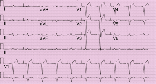
FIGURE 10-1
Question
Discussion
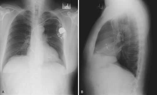
FIGURE 10-2
Question
Discussion
Final Diagnosis
Plan of Action
Intervention
Outcome
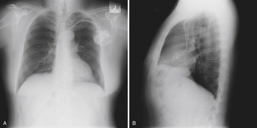
FIGURE 10-3 The new left ventricular lead and generator have been placed. The left ventricular lead appears to be in a satisfactory position, is lateral on the posteroanterior image (A) and appropriately anterior on the lateral image (B), consistent with positioning in the anterior interventricular vein.
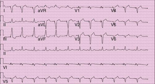
FIGURE 10-4 The QRS morphology is consistent with biventricular pacing. V1 demonstrates atypical right bundle branch morphology suggestive of some activation from the left ventricle. Lead I is strongly negative, as would be expected with left to right activation. The inferior leads, however, have a positive vector, as likely from the more superior left ventricular lead position.
Selected References
1. Asirvatham S.J. Cardiac anatomic considerations in pediatric electrophysiology. Indian Pacing Electrophysiol J. 2008;8(suppl. 1):S75–S91.
2. Asirvatham S.J. Electrocardiogram interpretation with biventricular pacing devices. In: Hayes D.L., Wang P.J., Sackner-Bernstein J. et al., et al, eds. Resynchronization and defibrillation for heart failure: a practical approach. Oxford, UK: Blackwell Publishing; 2008.
3. Corcoran S.J., Lawrence C., McGuire M.A. The valve of Vieussens: an important cause of difficulty in advancing catheters into the cardiac veins. J Cardiovasc Electrophysiol. 1999;10:804–808.
4. Habib A., Lachman N. et al. The anatomy of the coronary sinus venous system for the cardiac electrophysiologist. Europace. 2009;11(suppl 5):v15–v21.
5. Stellbrink C., Breithardt O.A., Franke A. et al. Technical considerations in implanting left ventricular pacing leads for cardiac resynchronisation therapy. Eur Heart J Suppl. 2004;6(D):D43–D46.
[/level-membership-for-cardiovascular-category][not-level-membership-for-cardiovascular-category]
History
Current Medications
Comments
Current Symptoms
Physical Examination
Laboratory Data
Electrocardiogram
Findings
Comments
Chest Radiograph
Findings
Focused Clinical Questions and Discussion Points
Question
Discussion
[/not-level-membership-for-cardiovascular-category]
