Chapter 38 Upper Cervical and Occipitocervical Arthrodesis
Advances in imaging, spinal surgical technique, and instrumentation have provided novel means of approaching, stabilizing, and treating pathology at the CMJ. Key advances in instrumentation, including novel occipital fixation devices, C1 lateral mass screws, and C2 pedicle screws, 1–3 have promoted the development of numerous methods for fixation of the upper cervical spine. This chapter emphasizes the technical aspects of the different types of fixation and fusion of the upper cervical spine and CMJ. Methods for fixation of odontoid fractures, atlantoaxial instabilities, and occipitocervical instabilities—with special emphasis on the latest developments and instrumentation methods—are discussed.
Ventral Approaches
Odontoid Fixation
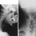
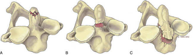
Odontoid fractures, a common injury of the cervical spine, are found in conjunction with almost 60% of atlas fractures and with 10% to 20% of all cervical fractures.4,5 Based on the Anderson and D’Alonzo nomenclature for odontoid fractures, almost 40% are type II fractures6 (Fig. 38- 1). Although conservative management should be considered, given the high rate of nonunion associated with these lesions, surgery is the gold standard of treatment. Historically, dorsal wiring techniques, such as C1-2 arthrodesis with halo-vest immobilization for 3 months, offered an excellent fusion rate (as high as 97%).7 The main shortcoming of wiring methods is the long-term loss of patient mobility from sacrifice of the atlantoaxial joint and prolonged halo-vest immobilization immediately after surgery.7 Odontoid screw fixation, introduced by Bohler8 and Nakanishi’s group,9 has eliminated the need for halo-vest immobilization, while preserving motion at C1-2: the fusion rate can be as high as 100% (92–100%),10 and it is one of the only motion-preservation stabilization procedures available in spine surgery.
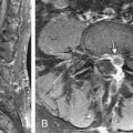
Other key contraindications to this procedure include exclusion of patients with disruption of the transverse atlantal ligament as seen on MRI,11 osteopenia with poor bone quality, inability to reduce a displaced fracture, and the presence of a type II fracture that extends across the base of the odontoid in an oblique plane. A disrupted transverse atlantal ligament results in dorsal migration of the fusion fragment during screw insertion; it does not address rupture of the transverse ligament even if the fracture heals. The inability to reduce a fracture appropriately to restore alignment and an oblique fracture line make capture of the fractured dens challenging. Osteopenia is a key contraindication that can result in “windshield wiping” of the screw with the potential to cause neurologic injury.
In the case of a ventral dislocation, the patient is placed supine with the neck extended or hyperextended and in a three-pin holder or halo tongs if preoperative traction is necessary. In the case of a dorsal dislocation, the patient is placed in a military chin-tuck position under fluoroscopic guidance. At our institution, we use intraoperative stealth image guidance to visualize bony anatomy in the coronal plane, eliminating the need for two image intensifiers. In a patient with a large barrel chest, it is difficult to obtain the necessary sagittal trajectory for screw placement. This problem can be corrected by translating the head and neck ventrally by hyperextending the neck with direct visualization using lateral fluoroscopy (Fig. 38-2). A very large chest can make the procedures technically impossible.
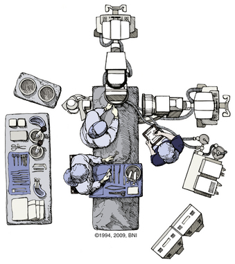
FIGURE 38-2 Positioning of two C-arm fluoroscopes for odontoid screw fixation.
(Used with permission from Barrow Neurological Institute.)
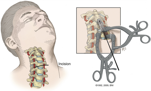
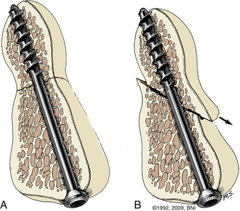
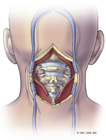
A transverse skin incision is made at the level of the cricothyroid junction, and the platysma is divided longitudinally to the ventral border of the sternocleidomastoid muscle. The dissection is performed using natural planes to the level of C4-5 (Fig. 38- 3). Blunt dissection proceeds rostrally to the level of the C2-3 disc space, and the retropharyngeal space is opened at C2. The medial borders of the longus colli muscles are coagulated and elevated laterally to maintain exposure. Next, it is important to expose the midline of the body of C2 because the midline keel of C2 is the landmark for screw placement. Doing so requires creating a midline trough through the anulus and disc at the C2-3 interspace. The placement of this entry site is critical because rostral placement of a screw can cause the shaft of the screw to lie too close to the overlying ventral cortex of C2. In this scenario the screw can cut out, or windshield-wipe out, of the C2 body, and pseudarthrosis can then develop.
More recently, image-guided navigation for placing odontoid screws has been employed. When this technique is used, the patient’s head is placed in a three-point fixation device and secured to the operating table. Using isocentric C-arm fluoroscopy, intraoperative images are obtained and 3D reconstruction is performed using the StealthStation (Medtronic, Minneapolis, MN). Using the coronal trajectory on the StealthStation, the midline of the C2 body is identified and a K-wire is advanced through the odontoid fracture. Real-time lateral fluoroscopy is used to monitor progress in the lateral plane until the K-wire approaches the cortex of the odontoid tip. Although the sagittal trajectory on the StealthStation may be used, it is not reliable. As force is applied on the C2 body during K-wire insertion, the body is pushed down and an error in sagittal trajectory is introduced, which can result in misplacement of the screw. As a result, we use image guidance for the coronal trajectory of the screw and lateral fluoroscopy for the sagittal trajectory and to monitor real-time progress of the K-wire and screw. Once the K-wire is placed, the bone can be drilled if it is very dense. The path is then tapped and a 4-mm screw is advanced under fluoroscopic guidance until it approaches the distal cortex of the dens. At this point, a cannulated titanium screw is selected (lag or fully threaded 4 mm). The screw is advanced and tightened until the screw head is just countersunk with respect to the body of C2 (Fig. 38-4). The screw length can be customized by measuring the K-wire depth on the fluoroscopic image.
Hangman’s Fracture
Traumatic spondylolysis of the C2 isthmus, also known as hangman’s fracture, can be treated surgically or with an external orthosis, depending on the extent of dislocation and angulation. There are three types of hangman’s fractures, according to the classification devised by Effendi and modified by Levine and Edwards.12 In type 1 injuries there is a normal C2-3 intervertebral disc and less than 3-mm displacement without angulation. The mechanism of injury is hyperextension with axial loading, and the fracture can be treated in an external orthosis. Type 2 injuries consist of disruption of the C2-3 disc space and ventrally angulated or displaced fractures. The mechanism is combined hyperextension and axial loading followed by hyperflexion. This injury can be treated surgically or by placing the patient in an external orthosis. Type 3 injuries involve ventral displacement with hyperflexion of the axis associated with unilateral or bilateral facet dislocations. The mechanism of the dislocation is flexion and distraction, with hyperextension responsible for the spondylolisthesis. This injury is treated surgically.
Direct reduction and fusion of a type 2 hangman’s fracture is possible by placing a screw through the pars and into the vertebral body. This cannot be performed in most cases given the size of the pars and the morphology of the fracture. If dorsal fusion of a hangman’s fracture is preferred, then screws are placed into the C1 and C3 lateral masses with the connecting rods as described in the section on dorsal upper cervical fixation. With a rib graft placed over the C1-3 dorsal arches, a multistranded titanium cable is passed under the rods and over the rib graft. With appropriate tensioning of the cable, the fractured C2 pars can be reduced, which enhances the fusion (Fig. 38-5).
Dorsal Upper Cervical Fixation
Occipitocervical Fixation
Occipitocervical fixation is used to correct deformities or instability at the occipitocervical junction. This fixation technique also can be used to treat atlantoaxial instability in patients who are not candidates for atlantoaxial fixation or who have failed previous attempts at C1-2 fusion.
Various methods can be used, but the general approach is as follows. After the patient is placed in a prone position in a three-point fixation device, it is critical to ensure appropriate neutral alignment of the head and the neck using lateral fluoroscopy and direct observation. Eyes must be looking forward and without a lateral tilt. Extensive flexion or extension should be avoided. A military chin-tuck position may be used to aid in exposure of the craniocervical junction and for placement of the C1 lateral mass screws (Fig. 38-6). Alternatively, the patient’s head and neck should be realigned appropriately before the final securing of the construct.
Adjunct Tools for Occipitocervical Fixation
Occiput-to-C1 Screw Fixation
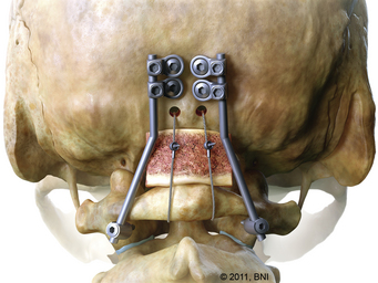
In cases of isolated occipitoatlantal dislocation, an occiput-to-C1 fusion may be performed via an occipital keel plate and the insertion of lateral mass screws into C1 or via a transarticular screw placed into the O-C1 joint13 (Fig. 38-7). The technical difficulty with insertion of a C1 lateral mass screw rests in the approach and placement of an entry point into C1. The C2 nerve root and its associated venous plexus are intimately associated with C1, and identification of the medial border of C1 as well as preparation for insertion of the lateral mass screw may result in injury or significant blood loss, especially in a small child.14 The depth of the anterior tubercle of C1 varies considerably and should be studied carefully on preoperative computed tomography scans before using lateral fluoroscopy of this structure to guide depth of C1 lateral mass screw placement.15 The entry point for placement of the pilot hole for a C1 lateral mass screw is in the middle of the lateral mass. The entry point for an O-C1 transarticular screw is similar to placement of a C1 lateral mass screw but is aimed more rostrally (usually 1 cm above the tip of the odontoid) to avoid the hypoglossal canal. The screw is placed via a K-wire similar to the technique described in the section on dorsal C1-2 transarticular screws. The judicious use of fluoroscopic or isocentric C-arm guidance minimizes damage to underlying tissues.
C1-2 Lateral Mass Fixation
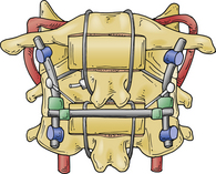
The bilateral insertion of polyaxial-head screws in the lateral mass of C1 and the pars interarticularis or the pedicle of C2, followed by a fluoroscopically controlled reduction maneuver and rod fixation, also known as the Goel or Harms technique, is a newer method for fixation of the C1-2 joint.1 Dorsal exposure of the C1-2 complex is performed and 3.5-mm polyaxial screws are inserted into the lateral masses of C1. Next, using fluoroscopy, two polyaxial screws are inserted into the pars interarticularis or pedicle of C2.
Dorsal C1-2 Transarticular Screws
Initially described by Grob and Magerl,12 this technique is used to fuse C1 to C2 by passing screws from the dorsal aspect of the C2 facet through the C1-2 joint so that it engages the middle of the ventral bone surface of the C1 lateral mass. When used in conjunction with an interspinous wired graft, this method of fixation is biomechanically a very stable construct.16
This technically challenging method of fixation is associated with significant hazards and potentials for complication. The technique is unsuitable for cases with a long-standing irreducible deformity, lateral mass destruction, torticollis, or rotatory subluxation of the joint. Vertebral artery injury is the most feared complication; therefore, an aberrant course of the vertebral artery in the C2 lateral mass is a strong contraindication.17 When the course or status of the vertebral artery is unclear, preoperative CT angiography is needed to study the vertebral artery to determine whether this technique is feasible. If the vertebral artery is damaged during placement of the first screw, it is important not to proceed with placement of the second screw. Unilateral transarticular C1-2 fixation, when combined with interspinous wire graft, provides sufficient immobilization and promotes fusion similar to bilateral fixation.18
C2 Intralaminal Fixation
Bilateral crossing C2 laminar screws have become popular as an alternative technique for C2 fixation.19 The authors reserve this technique when other types of C2 fixation are not possible or as a bail-out maneuver.
After the exposure, a high-speed drill is used to place a pilot hole pointed opposite the lamina to be fixated. The hole is drilled to a depth of 20 to 28 mm, and a 3.5- or 4.0-mm polyaxial screw is advanced into the lamina. To ensure that any possible cortical breakthrough is pointed dorsally through the laminar surface as opposed to ventrally into the spinal canal, the trajectory for screw insertion is kept less than the downslope of the lamina. A dental instrument is placed under the lamina during screw insertion to help detect any breakouts. In its correct final position, the head of the screw is at the base of the spinous process while lying flush within the lamina. A second screw is placed from the opposite base of the spinous process into the lamina similar to the first screw. Reported disadvantages of this technique include early hardware failure, breach of the dorsal lamina or ventral canal, and difficulty in bone graft or rod placements due to the position of the screw heads.20
Gallie-Brooks-Sonntag Fusion
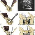
The Gallie-Brooks fusion, as modified by Sonntag, allows fixation of atlantoaxial instability via preparation of the dorsal lamina of the atlas and axis and preservation of the C2-3 interspinous ligament.21 Initially, the inferior aspect of C1 and superior aspects of C2 are roughened with a drill to create a suitable interface for fusion. A Kerrison punch is used to notch the inferior C2 hemilamina, and a loop of cable is passed under the dorsal arch of C1 in a caudal to rostral direction. A rectangular graft, approximately 1.5 cm × 3.5 cm, is then harvested (dorsal rib is now used instead of iliac crest) and trimmed to fit snugly between the dorsal arch of C1 and the lamina of C2. The loop cable is drawn over the spinous process of C2, and its ends are tightened. This one-point fixation construct does not counter rotatory or translatory movements. Therefore, it is recommended that this technique be used in combination with another form of fixation, such as placement of C1-2 transarticular screws or C1-2 lateral mass screws. Postoperatively, a hard collar is worn for approximately 6 weeks.
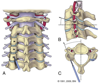
Lateral Mass Fixation (C3-6)
Screws are placed in the center of the lateral mass, which is defined by the groove between the lamina and the beginning of the lateral mass medially and the curving lateral edge laterally (Fig. 38-8). The trajectory is 30 degrees lateral and 30 degrees rostral (see Fig. 38-8). Screw lengths may be measured on a preoperative CT or intraoperatively by stopping the drill before it reaches the dorsal aspect of the lateral mass on lateral fluoroscopy. Placing the screws from the contralateral side of the table helps achieve correct angles. Good bone quality is key, and poor screw fixation invariably results in early screw pullout. Lateral mass screws are relatively contraindicated in patients with poor bone quality. The technique is associated with a risk of damage to a nerve root or vertebral artery. With appropriate rostral and lateral trajectories, both risks are minimized. Bicortical screw purchase is unnecessary and offers no biomechanical advantage compared to unicortical screws.18
Bone-Grafting Techniques
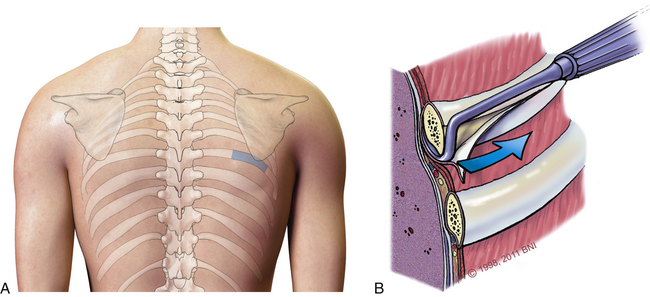
Possible sites for harvesting autologous grafts include the ribs, iliac crest, skull, and fibula. Grafts from the rib and iliac crest, which are good sources of tricortical, bicortical, or cancellous chips, are preferred. The rate of arthrodesis for grafts from ribs or the iliac crest is the same, but the rate of complications associated with harvesting a rib is lower.22
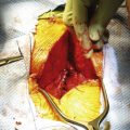
To harvest rib grafts, a linear incision is made in the skin over the rib surface (Fig. 38-9A). Blunt dissection with a Doyen rib dissector is used to detach the intercostal muscles and parietal pleura from the undersurface (Fig. 38-9B). The ends of the rib graft are cut sharply using a rib cutter or oscillating saw and smoothed to avoid a pneumothorax.
Brockmeyer D.L. Lateral mass screw fixation of C-1. J Neurosurg. 2007;107(Suppl 2):173-177.
Dickman C.A., Mamourian A., Sonntag V.K., Drayer B.P. Magnetic resonance imaging of the transverse atlantal ligament for the evaluation of atlantoaxial instability. J Neurosurg. 1991;75(2):221-227.
Galler R.M., Dogan S., Fifield M.S., et al. Biomechanical comparison of instrumented and uninstrumented multilevel cervical discectomy versus corpectomy. Spine. 2007;32(11):1220-1226.
Gonzalez L.F., Klopfenstein J.D., Crawford N.R., et al. Use of dual transarticular screws to fixate simultaneous occipitoatlantal and atlantoaxial dislocations. J Neurosurg Spine. 2005;3(4):318-323.
Grob D., Magerl F. Surgical stabilization of C1 and C2 fractures. Orthopade. 1987;16(1):46-54.
Hadley M.N., Browner C., Sonntag V.K. Axis fractures: a comprehensive review of management and treatment in 107 cases. Neurosurgery. 1985;17(2):281-290.
Maughan P.H., Horn E.M., Theodore N., et al. Avulsion fracture of the foramen magnum treated with occiput-to-C1 fusion: technical case report. Neurosurgery. 2005;57(3):E600.
Song G.S., Theodore N., Dickman C.A., Sonntag V.K. Unilateral posterior atlantoaxial transarticular screw fixation. J Neurosurg. 1997;87(6):851-855.
Wait S.D., Ponce F.A., Colle K.O., et al. Importance of the C1 anterior tubercle depth and lateral mass geometry when placing C1 lateral mass screws. Neurosurgery. 2009;65(5):952-956.
1. Harms J., Melcher R.P. Posterior C1-C2 fusion with polyaxial screw and rod fixation. Spine. 2001;26(22):2467-2471.
2. Resnick D.K., Lapsiwala S., Trost G.R. Anatomic suitability of the C1-C2 complex for pedicle screw fixation. Spine. 2002;27(14):1494-1498.
3. Stokes J.K., Villavicencio A.T., Liu P.C., et al. Posterior atlantoaxial stabilization: new alternative to C1-2 transarticular screws. Neurosurg Focus. 2002;12(1):E6.
4. Apuzzo M.L., Heiden J.S., Weiss M.H., et al. Acute fractures of the odontoid process. An analysis of 45 cases. J Neurosurg. 1978;48(1):85-91.
5. Hadley M.N., Browner C., Sonntag V.K. Axis fractures: a comprehensive review of management and treatment in 107 cases. Neurosurgery. 1985;17(2):281-290.
6. Koech F., Ackland H.M., Varma D.K., et al. Nonoperative management of type II odontoid fractures in the elderly. Spine. 2008;33(26):2881-2886.
7. Fielding J.W., Hawkins R.J., Ratzan S.A. Spine fusion for atlanto-axial instability. J Bone Joint Surg [Am]. 1976;58(3):400-407.
8. Bohler J. Operative treatment of injuries to cervical spine. Orthop Rev. 1986;15(1):58-59.
9. Chiba K., Fujimura Y., Toyama Y., et al. Treatment protocol for fractures of the odontoid process. J Spinal Disord. 1996;9(4):267-276.
10. Agrillo A., Russo N., Marotta N., Delfini R. Treatment of remote type II axis fractures in the elderly: feasibility of anterior odontoid screw fixation. Neurosurgery. 2008;63(6):1145-1150.
11. Dickman C.A., Mamourian A., Sonntag V.K., Drayer B.P. Magnetic resonance imaging of the transverse atlantal ligament for the evaluation of atlantoaxial instability. J Neurosurg. 75(2), 1991. 221–217, 1991
12. Grob D., Magerl F. Surgical stabilization of C1 and C2 fractures. Orthopaedics. 1987;16(1):46-54.
13. Gonzalez L.F., Klopfenstein J.D., Crawford N.R., et al. Use of dual transarticular screws to fixate simultaneous occipitoatlantal and atlantoaxial dislocations. J Neurosurg Spine. 2005;3(4):318-323.
14. Brockmeyer D.L. Lateral mass screw fixation of C-1. J Neurosurg. 2007;107(Suppl 2):173-177.
15. Wait S.D., Ponce F.A., Colle K.O., et al. Importance of the C1 anterior tubercle depth and lateral mass geometry when placing C1 lateral mass screws. Neurosurgery. 2009;65(5):952-956.
16. Rocha R., Sawa A.G., Baek S., et al. Atlantoaxial rotatory subluxation with ligamentous disruption: a biomechanical comparison of current fusion methods. Neurosurgery. 2009;64(Suppl 3):137-143.
17. Rocha R., Safavi-Abbasi S., Reis C., et al. Working area, safety zones, and angles of approach for posterior C-1 lateral mass screw placement: a quantitative anatomical and morphometric evaluation. J Neurosurg Spine. 2007;6(3):247-254.
18. Galler R.M., Dogan S., Fifield M.S., et al. Biomechanical comparison of instrumented and uninstrumented multilevel cervical discectomy versus corpectomy. Spine. 2007;32(11):1220-1226.
19. Kabir S.M., Casey A.T. Modification of Wright’s technique for C2 translaminar screw fixation: technical note. Acta Neurochir (Wien). 2009;151(11):1543-1547.
20. Parker S.L., McGirt M.J., Garces-Ambrossi G.L., et al. Translaminar versus pedicle screw fixation of C2: comparison of surgical morbidity and accuracy of 313 consecutive screws. Neurosurgery. 2009;64(5 Suppl 2):343-348.
21. Dickman C.A., Sonntag V.K., Papadopoulos S.M., Hadley M.N. The interspinous method of posterior atlantoaxial arthrodesis. J Neurosurg. 1991;74(2):190-198.
22. Ryken T.C., Heary R.F., Matz P.G., et al. Techniques for cervical interbody grafting. J Neurosurg Spine. 2009;11(2):203-220.
23. Maughan P.H., Horn E.M., Theodore N., et al. Avulsion fracture of the foramen magnum treated with occiput-to-C1 fusion: technical case report. Neurosurgery. 2005;57(3):E600.
24. Song G.S., Theodore N., Dickman C.A., Sonntag V.K. Unilateral posterior atlantoaxial transarticular screw fixation. J Neurosurg. 1997;87(6):851-855.