[level-membership-for-anesthesiology-category]
Chapter 20 Ultrasound-Guided Lumbar Spine Injections


 For novices, it is best to start with easy blocks such as intramuscular or trigger point injections.
 For a medial branch block, reaching the cranial part of the transverse process with the needle tip immediately at the first puncture attempt can be accomplished as follows: With a paramedian short-axis view between two transverse processes and a transducer movement from cranial to caudal, the first bony line encountered is the cranial edge of the transverse process.


Basic Principles of Ultrasound-Guided Injections
Ultrasound Machines, Transducers, and Knobology
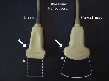
Today a huge variety of ultrasound machines in different sizes from different companies is available. Portable machines have reached quality levels comparable to larger scale gear. For applications in regional anesthesia and pain therapy, high-resolution technology combined with excellent musculoskeletal imaging properties is of great help to the practitioner. Linear broadband transducers with high frequencies up to 15 MHz are preferred when small structures close to the surface have to be targeted. Curved-array broadband probes with lower frequencies around 5 MHz are used for deeper targets. At least one of each of these two basic types of transducers should be available to physicians routinely performing ultrasound-guided interventions in pain management. Fig. 20-1 shows a typical linear probe on the left side of the image and a curved-array probe on the right with a schematic shape of the resulting sonographic images. Please note that the side of the mark on the transducer (arrow) is corresponding to the mark on the image (star). This is important for correct image orientation. Color-flow Doppler ultrasonography helps to identify vessels and is part of the basic machine equipment today. Finally, the operator has to be familiar with basic machine settings such as depth, gain, and focus.
Needles, Techniques, and Sterility
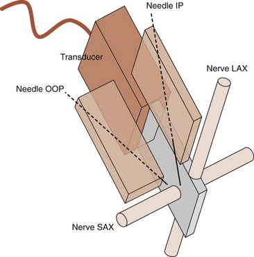
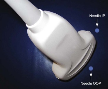
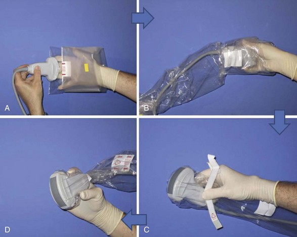
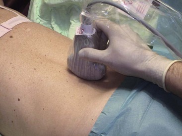
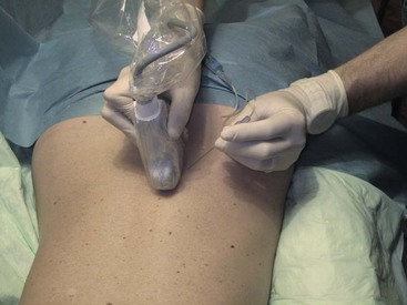
Needle choice depends on both target depth and operator preference. Better visualization is possible with larger diameter needles and shallow insertion angles; however, patient comfort is often associated with the contrary. Good choices are needles with facet tips and diameters between 20 and 25 gauges. Recently, higher reflective ultrasound needles have been developed and are the subject of evaluation at the moment. Image orientation can be short or cross axis (SAX; i.e., transverse plane) or long axis (LAX; i.e., longitudinal plane relative to the target nerve or the spinal column). Needle insertion can be out of plane or in plane relative to the LAX of the transducer’s footprint. Whereas out-of-plane techniques offer shorter access but only visualization of the needle tip, in-plane techniques are associated with a longer path to the target but visualization of the entire needle (Fig. 20-2). The needle insertion point for the out-of-plane technique is close to the longer side; for the in-plane technique, it is close to the shorter side of the transducer’s footprint (Fig. 20-3). Sometimes the transducer has to be turned 90 degrees after needle insertion to ensure proper positioning in a second plane. Sterile working conditions are mandatory for invasive procedures, including covering of the probe and use of sterile ultrasound gel. Special covers designed for this purpose are available today; the image shows how to cover a probe with such a shield (Fig. 20-4).
Sonography of the Lumbar Spine—Basic Scanning Sequence
The basic scanning sequence can be done before skin disinfection and sterile draping with nonsterile gel and no probe cover or after the preparation but then necessarily with sterile gel and a probe cover on. The patient is in prone position with a pillow under the stomach to compensate for lumbar lordosis. The sonographer sits on the patient’s left side facing the ultrasound machine next to the head of the patient. The basic scanning sequence consists of five standard planes and starts in the midline above the spinous processes of the lower lumbar spine (Fig. 20-5).
Standard Lumbar Paravertebral Planes and Relevant Sonoanatomy
 Median LAX (longitudinal view) above the spinous processes (Fig. 20-6): The cranial side is always left on the longitudinal views (note the corresponding marks or stars on the transducer and the image); the spinous processes regularly are lined up very close to the surface with dorsal bony shadowing below and can be counted upwards starting from the continuous bony line on the right side of the image, which is the sacrum.
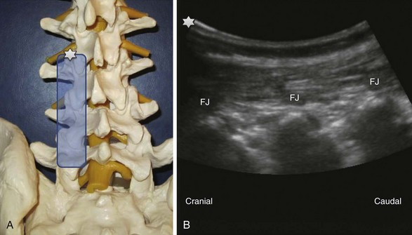
 Paramedian LAX (longitudinal view) above the facet joints (Fig. 20-7): Parallel shifting of the transducer to the lateral side without tilting produces an image of the facet joints or superior articular processes with dorsal shadowing; a typical wave line shaped figure can be recognized.
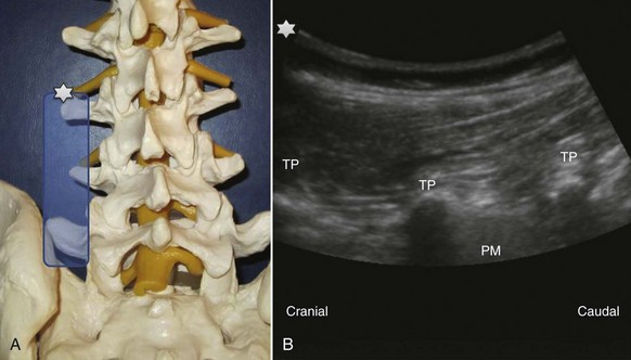
 Paramedian LAX (longitudinal view) above the transverse processes (Fig. 20-8): Shifting further lateral results in an image of the transverse processes (TP) alone without other bony landmarks. The scanning plane is longitudinal to the spine and thus the transverse processes are cut in a transverse way. Due to the convention of image orientation, the left part of each transverse process is the cranial end and the right part the caudal end. The transverse processes can be counted upwards from right to left starting from the continuous line of the sacrum like described above. Behind two transverse processes, the psoas muscle appears, where it is not covered by the shadows of the bone.
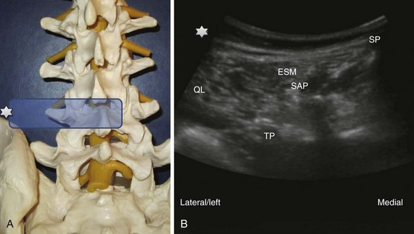
 Paramedian SAX (transverse view) above the transverse processes (Fig. 20-9): A 90-degree counterclockwise rotation of the transducer above the respective transverse process displays a transverse view with the spinous process, the superior articular process and the transverse process, the erector spinae muscle and the quadratus lumborum muscle. Ventrolateral to the quadratus lumborum, the kidney can be visible in the image.
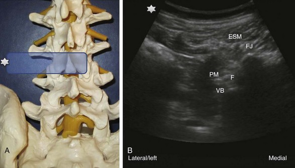
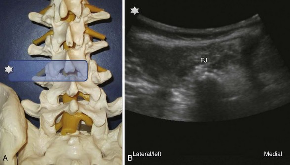
 Paramedian SAX (transverse view) between two transverse processes (Fig. 20-10): Parallel shifting of the transducer to the cranial side displays a transverse view between two transverse processes with the erector spinae muscle most superficial, the facet joint medial, the lateral border of the vertebral body more lateral and deeper, the psoas muscle, and the entry to the neuroforamen (F).
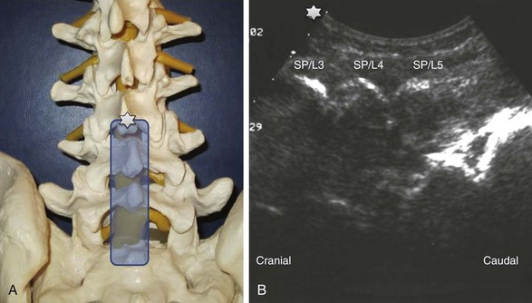
Lumbar Facet Nerve or Medial Branch Block
History and Literature
Lumbar medial branch block (i.e., facet nerve block) with ultrasound guidance instead of fluoroscopy was first described by the author’s group in 2004.1 The new methodology was developed in a model, and the paravertebral SAX and LAX views necessary for proper needle guidance were demonstrated. Lumbar regions of 20 volunteers were scanned to assess the visibility of the sonoanatomical landmarks and to derive estimates of typical distances in a total of 240 views. Finally, the practicability of the new method was tested in a case series of 28 blocks in clinical patients with suspected facet joint–derived pain. A second study2 confirmed the accuracy of ultrasound-guided lumbar medial branch blocks in a cadaveric model by means of CT. The target point was defined as the groove at the cephalad margin of the transverse (or costal) process L1-L5 (medial branch T12-L4) adjacent to the superior articular process. Axial transverse CT scans, with and without 1 mL of contrast dye, followed to evaluate needle positions and spread of contrast medium. Forty-five of 50 needle tips were located at the exact target point. The remaining five were within 5 mm of the target. In 47 of 50 cases, the applied contrast dye reached the groove where the nerve is located, corresponding to an overall simulated block success rate of 94% (95% confidence interval, 84% to 98%). Shim and co-workers3 performed 101 ultrasound-guided lumbar medial branch blocks according to our published technique in 20 patients. Needle position was confirmed with C-arm fluoroscopy. They reported a high success rate of 95% but also two needle positions associated with intravascular spread of contrast dye. A certain limitation of the technique is obesity, as was shown in a recent study by Rauch et al.4 In 20 patients with BMIs above 30, a success rate of only 62% could be achieved under ultrasound guidance alone.
Facet Joint–Mediated Pain
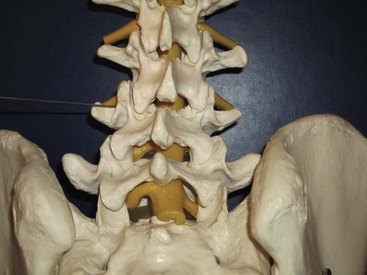
Facet joint–mediated pain has been identified as a cause of low back pain since 1933. The facet or zygapophyseal joints are often affected by mechanical derangements or degenerative alterations (Fig. 20-11). As a consequence, reflex muscular spasm or referred pain can arise. Facet joint–mediated pain commonly appears as lumbosacral pain with or without sciatic pain predominantly proximal to the knee, particularly associated with a twisting or rotary strain of the lumbosacral region. The pain can be uni- or bilateral and is typically enhanced by hyperextension of the spine or locally applied pressure on the facet joints. However, clinical examinations and radiographic imaging as well as scoring systems lack the necessary positive and negative predictive value to diagnose facet joint–mediated pain. A test series of at least two positive highly selective low-volume nerve blocks or intraarticular injections is mandatory to confirm the diagnosis because the false-positive rate of a single successful block is 38%. With a correct diagnosis, radiofrequency treatment can significantly improve patients’ symptoms for a long time.
Innervation of the Facet Joint and Target Point for the Block
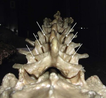
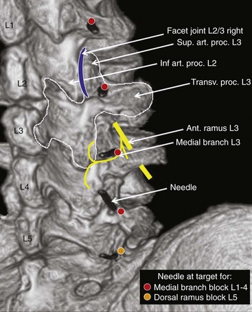
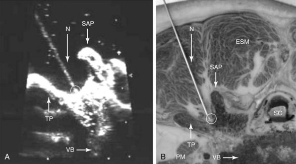
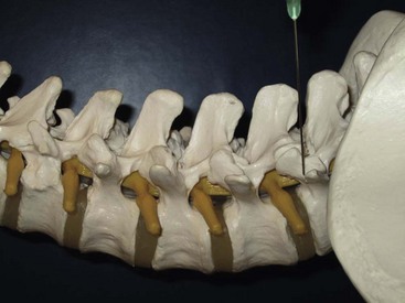
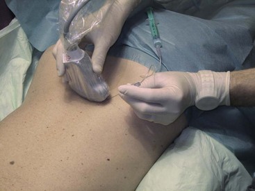
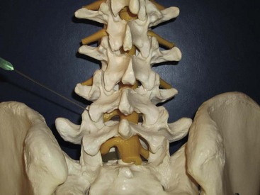
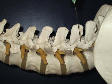
Each lumbar facet joint is innervated by the two medial branches from the segments above and below. The facet nerve is the medial branch of the dorsal ramus of the spinal nerve. To anesthetize the L3-L4 joint for example, blocks of the L2 and L3 medial branch at the transverse processes of the L3 and the L4 vertebrae are needed. At L5, the entire dorsal ramus instead of a medial branch is present. Each medial branch runs over the junction of the cranial edge of the transverse and superior articular processes (Fig. 20-12). This is the target point for an ultrasound-guided medial branch block (Figs. 20-13 to 20-16). It is approached with the transducer in a paramedian SAX and an in-plane needle direction from lateral to medial (Fig. 20-17). After bony contact, the transducer has to be rotated 90 degrees clockwise in a paramedian LAX to ensure the tip of the needle on the cranial end of the transverse process in a second plane (Fig. 20-18).

Technique
The patient is placed prone with a pillow under the stomach to compensate for lumbar lordosis. The physician sits on the left side of the patient facing the ultrasound machine close to the head of the patient. Disinfection and sterile draping are applied. The transducer is covered, and sterile gel is used. First, a complete basic scanning sequence of the lumbar region as described above is performed to ensure correct localization. If preferred, skin markers can be used. A paramedian SAX plane above the target transverse process is set (Fig. 20-9). After performing a skin wheal, the immobile needle with a syringe attached is inserted in plane approximately 45 degrees from lateral to medial (Figs. 20-14 and 20-17) and advanced until bony contact is accomplished. Then the transducer is rotated 90 degrees clockwise into a paramedian LAX (Fig. 20-18). Under tiny movements of the needle (to and fro), this second plane is necessary to visualize and verify the position of the needle tip on the cranial end of the transverse process (Fig. 20-8). If the tip of the needle is too caudal, it has to be replaced accordingly. Finally, the transducer is rotated back 90 degrees counterclockwise into SAX and the local anesthetic is injected (0.5 to 1 mL) under direct vision. A certain volume spread should be visible at the tip of the needle. Then the procedure is repeated for the next relevant segment.
Facet Joint Injection
History and Literature
A technique for ultrasound-guided periarticular lumbar facet joint injections was published in a German orthopedic journal in 1997 for the first time.5 Galiano et al6 showed that intraarticular facet joint injections are feasible under ultrasound guidance alone. In their prospective randomized clinical trial,7 an ultrasound group was compared with a CT group. In 16 of the 18 patients in the ultrasound group, in which the target was clearly visible, needle placement was successful and comparable to CT-guided interventions. Procedure time was 14.3 minutes in the ultrasound versus 22.3 minutes in the CT group. The aim of another study8 of this group was to provide a teaching tool to facilitate the acquirement of periradicular and facet joint infiltration techniques in the cervical and lumbar spine. By use of a dedicated image navigation and reconstruction system, sonographic images were generated and fused with the collected CT data set. This allowed instant comparison of both imaging techniques. O’Neill et al9 used ultrasound-guided stimulating needles for an experimental pain model in volunteers. Two electrode needles were placed on either side of a lumbar facet joint to induce experimental low back pain for 10 minutes with continuous stimulation.
Technique
The target point for an intraarticular facet joint injection is displayed in the corresponding images (Figs. 20-19 and 20-20). The practical performance is similar to that of the medial branch block. Needle insertion is guided in a paramedian SAX view above the facet joint visualizing the double contour of and the entry into the joint (Fig. 20-21). Similar to medial branch blocks, the needle is advanced from lateral to medial in plane to the transducer until bony contact is made. Injection of 0.5 mL of volume is enough for one facet joint.
Other Applications
Selective Lumbar Nerve Root or Periradicular Injection
Inadvertent intravascular injections during ultrasound-guided selective lumbar transforaminal nerve root injections cannot be ruled out completely at the moment. Reports of rare but devastating complications such as paraplegia caused by a spinal cord infarction secondary to inadvertent injection of particulate material in a radicular artery10 under fluoroscopic or CT scan guidance are serious warnings. Because of this, most practitioners recommend not to perform ultrasound-guided selective nerve root injections at the moment, although they seem to be technically possible.11
Future Developments
Ultrasound-guided injection techniques in low back pain are an evolving field and will definitely gain more importance in the near future, maybe together with the development of sophisticated three-dimensional sonographic imaging techniques. Virtual reality imaging with real-time ultrasound guidance for facet joint injection has recently been described in a pilot study12 and was successfully used to track both the transducer and the needle in a three-dimensional environment. Further scientific and technological advances are needed to finally bring these fascinating applications into clinical practice.
1 Greher M, Scharbert G, Kamolz LP, et al. Ultrasound-guided lumbar facet nerve block: a sonoanatomic study of a new methodologic approach. Anesthesiology. 2004;100(5):1242-1248.
2 Greher M, Kirchmair L, Enna B, et al. Ultrasound-guided lumbar facet nerve block: accuracy of a new technique confirmed by computed tomography. Anesthesiology. 2004;101(5):1195-1200.
3 Shim JK, Moon JC, Yoon KB, et al. Ultrasound-guided lumbar medial-branch block: a clinical study with fluoroscopy control. Reg Anesth Pain Med. 2006;31(5):451-454.
4 Rauch S, Kasuya Y, Turan A, et al. Ultrasound-guided lumbar medial branch block in obese patients: a fluoroscopically confirmed clinical feasibility study. Reg Anesth Pain Med. 2009;34(4):340-342.
5 Küllmer K, Rompe JD, Löwe A, et al. [Ultrasound image of the lumbar spine and the lumbosacral transition. Ultrasound anatomy and possibilities for ultrasonically-controlled facet joint infiltration]. Z Orthop Ihre Grenzgeb. 1997;135(4):310-314.
6 Galiano K, Obwegeser AA, Bodner G, et al. Ultrasound guidance for facet joint injections in the lumbar spine: a computed tomography-controlled feasibility study. Anesth Analg. 2005;101(2):579-583.
7 Galiano K, Obwegeser AA, Walch C, et al. Ultrasound-guided versus computed tomography-controlled facet joint injections in the lumbar spine: a prospective randomized clinical trial. Reg Anesth Pain Med. 2007;32(4):317-322.
8 Galiano K, Obwegeser AA, Bale R, et al. Ultrasound-guided and CT-navigation-assisted periradicular and facet joint injections in the lumbar and cervical spine: a new teaching tool to recognize the sonoanatomic pattern. Reg Anesth Pain Med. 2007;32(3):254-257.
9 O’Neill S, Graven-Nielsen T, Manniche C, et al. Ultrasound guided, painful electrical stimulation of lumbar facet joint structures: an experimental model of acute low back pain. Pain. 2009;144(1-2):76-83.
10 Kennedy DJ, Dreyfuss P, Aprill CN, et al. Paraplegia following image-guided transforaminal lumbar spine epidural steroid injection: two case reports. Pain Med. 2009;10(8):1389-1394.
11 Galiano K, Obwegeser AA, Bodner G, et al. Real-time sonographic imaging for periradicular injections in the lumbar spine: a sonographic anatomic study of a new technique. J Ultrasound Med. 2005;24(1):33-38.
12 Clarke C, Moore J, Wedlake C, et al. Virtual reality imaging with real-time ultrasound guidance for facet joint injection: a proof of concept. Anesth Analg. 2010;110(5):1461-1463.
[/level-membership-for-anesthesiology-category][not-level-membership-for-anesthesiology-category]
Chapter 20 Ultrasound-Guided Lumbar Spine Injections
For novices, it is best to start with easy blocks such as intramuscular or trigger point injections. For a medial branch block, reaching the cranial part of the transverse process with the needle tip immediately at the first puncture attempt can be accomplished as follows: With a paramedian short-axis view between two transverse processes and a transducer movement from cranial to caudal, the first bony line encountered is the cranial edge of the transverse process.Basic Principles of Ultrasound-Guided Injections
Ultrasound Machines, Transducers, and Knobology
Today a huge variety of ultrasound machines in different sizes from different companies is available. Portable machines have reached quality levels comparable to larger scale gear. For applications in regional anesthesia and pain therapy, high-resolution technology combined with excellent musculoskeletal imaging properties is of great help to the practitioner. Linear broadband transducers with high frequencies up to 15 MHz are preferred when small structures close to the surface have to be targeted. Curved-array broadband probes with lower frequencies around 5 MHz are used for deeper targets. At least one of each of these two basic types of transducers should be available to physicians routinely performing ultrasound-guided interventions in pain management. Fig. 20-1 shows a typical linear probe on the left side of the image and a curved-array probe on the right with a schematic shape of the resulting sonographic images. Please note that the side of the mark on the transducer (arrow) is corresponding to the mark on the image (star). This is important for correct image orientation. Color-flow Doppler ultrasonography helps to identify vessels and is part of the basic machine equipment today. Finally, the operator has to be familiar with basic machine settings such as depth, gain, and focus.
Needles, Techniques, and Sterility
Needle choice depends on both target depth and operator preference. Better visualization is possible with larger diameter needles and shallow insertion angles; however, patient comfort is often associated with the contrary. Good choices are needles with facet tips and diameters between 20 and 25 gauges. Recently, higher reflective ultrasound needles have been developed and are the subject of evaluation at the moment. Image orientation can be short or cross axis (SAX; i.e., transverse plane) or long axis (LAX; i.e., longitudinal plane relative to the target nerve or the spinal column). Needle insertion can be out of plane or in plane relative to the LAX of the transducer’s footprint. Whereas out-of-plane techniques offer shorter access but only visualization of the needle tip, in-plane techniques are associated with a longer path to the target but visualization of the entire needle (Fig. 20-2). The needle insertion point for the out-of-plane technique is close to the longer side; for the in-plane technique, it is close to the shorter side of the transducer’s footprint (Fig. 20-3). Sometimes the transducer has to be turned 90 degrees after needle insertion to ensure proper positioning in a second plane. Sterile working conditions are mandatory for invasive procedures, including covering of the probe and use of sterile ultrasound gel. Special covers designed for this purpose are available today; the image shows how to cover a probe with such a shield (Fig. 20-4).
