[level-membership-for-cardiovascular-category]
1 Transesophageal Echocardiography
The role of transesophageal echocardiography (TEE) in the diagnosis and management of patients with suspected and overt cardiac disease has evolved with time as a result of refinements in technology and the addition of three-dimensional (3D) TEE.1,2 The portable nature of the technique allows the examination to be performed in a diverse array of clinical settings that include the outpatient ambulatory clinic, intensive care unit, catheterization laboratory, and operating room. Currently, TEE accounts for approximately 5% to 10% of all echocardiography studies performed.
Performance of Transesophageal Echocardiography
Transesophageal echocardiography is a semi-invasive procedure that should be performed only by a properly trained physician who understands the indications and potential complications of the procedure. Both technical and cognitive skills are required for the competent performance and interpretation of TEE studies (Box 1-1), and guidelines on training have been published.2 The physician should be assisted by an experienced sonographer whose tasks are to ensure that optimal images are obtained by adjusting the controls of the echocardiographic system and to ensure safety by monitoring the responses of the patient during the procedure. Although family members or friends are usually not allowed in the room when the procedure is being performed, there are situations in which their presence can be helpful. The presence of a parent can have a calming effect when one is dealing with an apprehensive teenager. A friend or relative who speaks the same language can relieve anxiety when dealing with an anxious patient who is not fluent in English.
Box 1-1
Cognitive And Technical Skills Required For The Performance Of Transesophageal Echocardiography
Cognitive Skills
Knowledge of appropriate indications, contraindications, and risks of TEE
Understanding of differential diagnostic considerations in each clinical case
Knowledge of physical principles of echocardiographic image formation and blood flow velocity measurement
Familiarity with the operation of the ultrasonographic instrument, including the function of all controls affecting the quality of the data displayed
Knowledge of normal cardiovascular anatomy, as visualized tomographically
Knowledge of alterations in cardiovascular anatomy resulting from acquired and congenital heart diseases
Knowledge of normal cardiovascular hemodynamics and fluid dynamics
Knowledge of alterations in cardiovascular hemodynamics and blood flow resulting from acquired and congenital heart diseases
Understanding of component techniques for general echocardiography and TEE, including when to use these methods to investigate specific clinical questions
Ability to distinguish adequate from inadequate echocardiographic data and to distinguish an adequate from an inadequate TEE examination
Knowledge of other cardiovascular diagnostic methods for correlation with TEE findings
Ability to communicate examination results to patient, other health care professionals, and medical record
Technical Skills
Proficiency in performing a complete standard echocardiographic examination, using all echocardiographic modalities relevant to the case
Proficiency in safely passing the TEE transducer into the esophagus and stomach and in adjusting probe position to obtain the necessary tomographic images and Doppler data
Proficiency in correctly operating the ultrasonographic instrument, including all controls affecting the quality of the data displayed
Proficiency in recognizing abnormalities of cardiac structure and function as detected from the transesophageal and transgastric windows, in distinguishing normal from abnormal findings, and in recognizing artifacts
Proficiency in performing qualitative and quantitative analysis of the echocardiographic data
From Pearlman AS, Gardin JM, Martin RP, et al: Guidelines for physician training in transesophageal echocardiography: recommendations of the American Society of Echocardiography Committee for Physician Training in Echocardiography. J Am Soc Echocardiogr 5:187-194, 1992.
Transesophageal echocardiography should be performed in a spacious room that can comfortably accommodate a stretcher. The room should be equipped with an oxygen outlet and suction facilities. A pulse oximeter should be available, to be used mainly in cyanotic patients and patients with severe lung disease. The TEE probe should be carefully examined before each use. In addition to visual inspection, it is important to palpate the probe, particularly the flexion portion, to ensure that there is no unusual wear and tear of the probe.3 Stretching of the steering cables may result in increased flexibility and mobility of the probe tip with buckling of the probe tip within the esophagus.4 This phenomenon is associated with a poor TEE image and resistance to probe withdrawal. The probe should be advanced into the stomach and straightened by retroflexion of the extreme antiflexed probe tip. We have also detected perforation of the TEE probe sheath by a ruptured steering cable and recommend inspection of the casing for any protruding wires before probe insertion.3 The flexion controls need to be tested on a regular basis. Anterior flexion should exceed 90°, and right and left flexion should approach 90°.
Preparation Of Patient
Patients should be contacted at least 12 hours before the procedure and instructed to fast for at least 4 hours before the procedure. They are informed that they should be accompanied, because they will not be able to drive or return to work for several hours owing to the lingering effect of sedation. On the day of the study, the procedure is explained in detail, and informed consent is obtained. Patients are told to expect mild abdominal discomfort and gagging following the insertion of the probe and are reassured that these responses are transient. A 20-gauge intravenous cannula is then inserted for administration of medications and contrast agents, if necessary. Lidocaine hydrochloride spray is routinely used for topical anesthesia, which should cover the posterior pharynx and tongue. We usually use diazepam 2 to 10 mg intravenously for sedation.5 Midazolam at 0.05 mg/kg, with a total dose between 1 and 5 mg, can also be used.
Sedation is used in about 85% of our patients and should be more sparingly used in elderly patients, because they tend to be more stoic and the effect of sedation tends to be more prolonged. On the other hand, sedation is essential in young, anxious patients and when the study is expected to be protracted. We aim for light sedation so that at the end of the procedure the patients are awake and can leave with an escort. Heavy sedation is needed in situations in which blunting the hemodynamic responses to the procedure is desirable, as with a patient undergoing TEE for suspected aortic dissection.6
It has not been our practice to use anticholinergic agents such as glycopyrrolate to decrease salivation. In rare circumstances in which there is excessive salivation, it is usually adequate to simply instruct the patient to let the saliva dribble onto a towel placed under the chin, or remove the saliva by intermittent suction. Bacteremia is not a significant risk in TEE, and we do not use antibiotic prophylaxis to prevent endocarditis even in patients with prosthetic valves.7,8
Esophageal Intubation
We perform the TEE study with the patient in the left decubitus position. The physician, sonographer, and echocardiographic system are all positioned on the left-hand side of the patient.5 Artificial teeth or dentures are routinely removed. The flexion controls should be unlocked to allow for maximum flexibility of the probe when it is being inserted. The patient’s head should be in a flexed position. The tip of the probe is kept relatively straight and gently advanced to the back of the throat. It should be maintained in a central position, because deviation to either side increases the likelihood that it may become lodged in the piriform fossa. (See Fig. 2-2) The operator can facilitate this process by inserting one or two fingers into the patient’s oropharynx to direct the path of the probe. Gentle pressure is exerted, and the patient is instructed to swallow. The swallowing mechanism helps guide the probe into the esophagus. In older patients, cervical spondylosis with prominent protrusion into the posterior pharynx can create difficulty with passage of the probe.5 Manually depressing the back of the tongue provides more room, allowing the TEE probe to assume a less acute angle and facilitating intubation of the esophagus. If significant resistance is encountered when the probe is advanced, it is prudent to withdraw the probe and then initiate a new attempt. In experienced hands, the rate of failure of esophageal intubation should be less than 2%.5,9
Inadvertent passage of the probe into the trachea can occur, particularly in deeply sedated patients. The development of stridor and incessant cough should alert the operator of this possibility. Furthermore, it would be difficult to advance the probe beyond 30 cm from the teeth, and the image quality is usually poor.5
Image Format
There is no general agreement on how the imaging planes should be displayed. Our preference is to orient the images such that the right-sided structures are on the left side of the screen and the left-sided on the right. The apex of the imaging plane with the electronic artifact is at the top of the screen. Thus, in longitudinal views, superior structures are to the right of the screen and the inferior to the left.10
Standard Imaging Planes
The TEE probe should be capable of multiplane imaging and preferably also real-time 3D imaging. The imaging plane is steered electronically from 0° to 180° by means of a pressure-sensitive switch, providing views that are unobtainable using monoplane and biplane probes. The following discussion focuses only on standard imaging views routinely performed at the University of Ottawa Heart Institute using multiplane TEE (Table 1-1). These views are considered “standard” because they have important clinical relevance and can be obtained in most patients with specific imaging planes. Further advances in image quality and image analysis of 3D TEE will likely facilitate the rapid acquisition of these imaging planes.
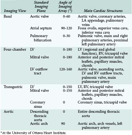
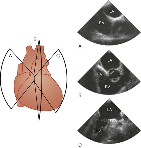
Four basic maneuvers are used to obtain specific tomographic views with TEE.11 The first relates to the positioning of the probe by advancement or withdrawal of the probe. Although this is a simple maneuver, it is the most crucial, and the imaging views can be conveniently categorized according to the location of the TEE probe within the esophagus or stomach into four groups: basal, four-chamber, transgastric, and aortic views (Fig. 1-1). The second maneuver involves rotation of the probe from side to side. This is particularly useful when using longitudinal imaging planes, which provide a better demonstration of the continuity between vertically aligned structures such as the superior vena cava and the arch vessels (Fig. 1-2).10,11 Steering the imaging plane using the pressure-sensitive switch is the third maneuver to obtain different tomographic views (Fig. 1-3). The accompanying images in Figures 1-1, 1-2, and 1-3 represent the typical images obtained with one of the basic maneuvers and provide the starting points for further adjustment of the imaging plane to obtain optimal long- or short-axis views of specific structures. This may be achieved using the fourth maneuver, which involves manipulation of the anterior-posterior and right-left flexion control knobs. The availability of a steerable imaging plane has drastically reduced the need to use the flexion knobs, but there are situations in which these knobs play a crucial role in obtaining proper tomographic views.11 These maneuvers provide an almost infinite number of imaging planes. Table 1-1 summarizes the standard imaging planes and the cardiac structures evaluated in these four groups of views.

Basal Views
Aortic Valve
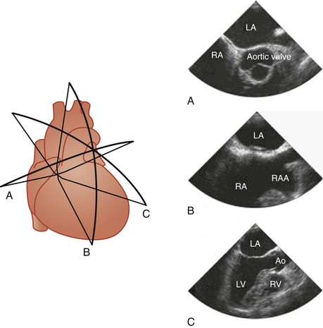
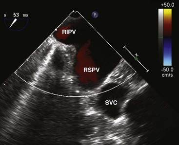
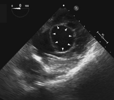
A short-axis view of the aortic valve can be obtained with the probe at about 30 to 35 cm from the teeth. The left coronary cusp often appears to have nodular thickening if the aortic valve is cut obliquely, which is often the case at 0°.10 Steering the imaging plane to 30° to 60° should eliminate this artifact by providing an optimal short-axis view of the aortic valve (see Fig. 1-3, A).11 A slight pull-back of the transducer should allow visualization of both the left and right coronary arteries (Fig. 1-4). The left coronary artery can be followed to its bifurcation into the left anterior descending and circumflex arteries. The right coronary artery is more difficult to display, and only the proximal 2 to 3 cm is usually seen. Other structures well seen in this view are the left atrial appendage and left pulmonary veins. The partition between these structures can be quite bulbous and should not be confused with an abnormal intracardiac mass (Fig. 1-5).12 Rotating the probe to the right should reveal the right pulmonary veins.
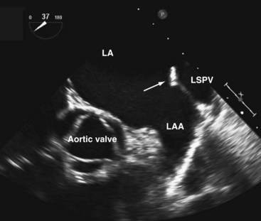
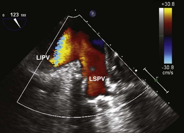
We like the horizontal plane in imaging the four pulmonary veins. The left and right pulmonary veins are imaged separately. When one pulmonary vein is identified, a slight translational movement of the probe should bring out the other, because the orifices of the superior and inferior pulmonary veins are in close proximity. The inferior pulmonary veins run horizontal to the imaging plane, whereas the superior veins are more anterior and at an obtuse angle, making them more suitable for Doppler assessment. It is feasible to image the superior and inferior pulmonary veins, left or right, in the same view using the vertical plane and imaging can be facilitated with the use of color flow imaging (Figs. 1-6 and 1-7). The right and left atrial appendages wrap around the great arteries anteriorly. The left atrial appendage is more prominent and can consist of multiple lobes (Fig. 1-8).13
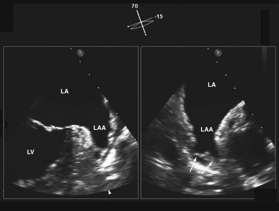
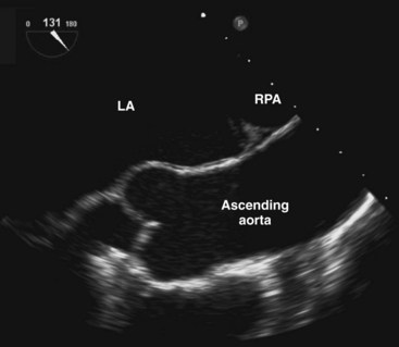
A comprehensive interrogation using multiple imaging planes should be performed to exclude left atrial appendage thrombus in the appropriate clinical setting. The right atrial appendage is smaller and triangular in shape (see Fig. 1-3, B). The endocardial surfaces of both appendages are corrugated and should not be confused with small thrombi.12 A long-axis view of the aorta can be achieved with the imaging plane at about 120° (Fig. 1-9). A more rightward imaging plane, such as 150°, may be needed if the ascending aorta is dilated and tortuous. This view allows the visualization of a longer length of the ascending aorta and thus significantly reduces the blind spot caused by the interposing trachea.
Atrial Septum
We prefer to image the atrial septum using the longitudinal plane at 90° to 120°. The fossa ovalis, which is the thinnest part of the atrial septum, and the continuity of the superior vena cava with the RA are very well demonstrated in this view (see Fig. 1-3, B). This view is particularly valuable in demonstrating the sinus venosus atrial septal defect, which is usually located just inferior to the entrance of the superior vena cava.14,15 The foramen ovale, if present, is located at the superior aspect of the fossa ovalis and is readily seen in this view. It is important to advance the probe to the level of the inferior vena cava so as not to neglect the inferior aspect of the atrial septum.16 Careful sweep of the atrial septum with left-right rotation is needed to visualize the entire atrial septum. Continuous rotation from right to left will sequentially demonstrate the left ventricular (LV) outflow tract and the right ventricular (RV) outflow tract (see Fig. 1-2, B).
Pulmonary Bifurcation
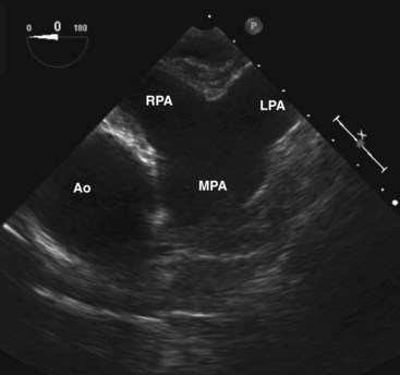
The pulmonary bifurcation view is achieved by withdrawal of the probe with the imaging plane at 0°. The pulmonic valve and main pulmonary artery are best seen slightly superior to the aortic valve (Fig. 1-10). The pulmonic valve is thinner than the aortic valve and is usually difficult to image in true cross section. Further slight withdrawal allows imaging of the pulmonary bifurcation. The entire length of the right pulmonary artery, but only the very proximal portion of the left pulmonary artery, can be seen. The right pulmonary artery can usually be followed to its first bifurcation by rotation of the probe rightward, but this maneuver is better performed with the longitudinal plane at 90°. Gradual rotation from left to right provides good visualization in cross section of the entire right pulmonary artery and its first bifurcation. This is an important view in the detection of proximal pulmonary emboli.17,18
Four-Chamber Views
Four-chamber views are obtained with the transducer within the middle to lower esophagus (see Fig. 1-1, B). It is difficult to image the left ventricle in its true long axis. Excessive anterior flexion should be avoided to prevent foreshortening of the ventricles. Indeed, to optimize visualization of the left ventricle, it is advisable to withdraw the probe slightly and at the same time attempt gentle retroflexion while maintaining adequate contact between the imaging surface and the esophagus. In the setting of a dilated and unfolded aorta, rotating the imaging plane to about 20° to 30° may be necessary to obtain the four-chamber view without the aorta obscuring the tricuspid valve and part of the RV.
Left Ventricle
The inferior septum and anterolateral wall are usually seen in the four-chamber view (see Fig. 1-1, B). The LV apex is difficult to visualize, particularly in patients with a dilated LV. In addition to retroflexion, rightward flexion can often be helpful to minimize foreshortening of the LV. Far-field imaging can be improved by decreasing the transmission frequency or by using harmonic imaging. A continuous sweep from 0° to 180° should be performed to examine the different left ventricular segments so as to have a comprehensive assessment of left ventricular global and regional function (see Fig. 1-2, C).
Mitral Valve
The mitral valve is well seen using the four-chamber view, but the depth of the imaging plane should be reduced to enhance the resolution of the image (see Figs. 1-1, B, and 1-2, C). To identify the individual scallops of the anterior and posterior mitral leaflets, a careful sweep from 0° to 180° should be made. The technique of visualizing specific scallops of the mitral leaflets has been published,19 but patient-to-patient variation should be kept in mind. The presence of a good long-axis view of the aortic valve and proximal ascending aorta, usually at 120°, is a good indication that the middle scallops of both the anterior and the posterior mitral leaflets are imaged and provides the internal reference for the analysis of the other imaging planes. Both papillary muscles can be imaged, but usually not in the same plane. The subvalvular chords are seldom completely imaged because they are frequently obscured by the mitral leaflets. The morphologic information obtained from this view should be corroborated by the short-axis view of the mitral valve obtained from the transgastric view, which also allows a better assessment of the subvalvular structures, including the papillary muscles and chords. Four-chamber views are ideal for the assessment of mitral regurgitation in relation to the number of regurgitant jets, the direction of the jets, and the severity of regurgitation.20,21
Left Ventricular Outflow Tract
We like to image the left ventricular outflow tract at 120° to 160°, because the outflow tract has a horizontal alignment in this plane that may allow optimal imaging even in the setting of a prosthetic aortic valve (see Fig. 1-3, C). The opening and closing of the aortic valve as well as the presence or absence of aortic regurgitation can be well visualized. The proximal ascending aorta is present in this view. A slight withdrawal of the probe will allow more of the ascending aorta to be visualized (see Fig. 1-9). A slight rotation to the left will show the RV outflow tract with the thin pulmonic valve. The motion of the pulmonic valve and the presence or absence of pulmonic regurgitation can be adequately assessed using this view.
Transgastric Views
Left Ventricle
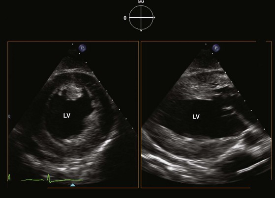
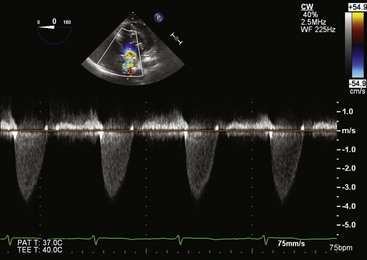
Multiple cross sections of the LV can usually be obtained using the transgastric approach (see Fig. 1-1, C, and Fig. 1-11). These are the views commonly used in the intraoperative assessment of LV function.19 Optimization of the short-axis views of the left ventricle can be achieved with leftward rotation accompanied by leftward flexion. To visualize the LV apex, gentle advancement of the probe is required together with slight retroflexion. In our experience, the short-axis view of the LV apex can be obtained in about 60% of cases. Another way to visualize the LV apex is to use the longitudinal plane at about 90° (see Fig. 1-11). Careful lateral rotation can be used to obtain comprehensive regional assessment of the LV. Leftward rotation of this imaging plane can yield a good alignment with the LV outflow tract and aortic valve to allow accurate measurement of the transaortic pressure gradients in the setting of aortic stenosis (Fig. 1-12).22 The RV can be seen with rightward rotation of the probe. Both short- and long-axis views of the tricuspid valve are achievable, although the tricuspid valve and its papillary muscles are better assessed with the long-axis plane.
Mitral Valve
The mitral valve can be best assessed using the horizontal imaging plane with the transducer brought up to near the gastroesophageal junction (Fig. 1-13). Anterior flexion and leftward flexion are usually required to optimize this view. Adjusting the imaging plane to about 20° will help to bring out the lateral commissure. This view provides unambiguous assessment of the individual scallops of both the anterior and posterior mitral leaflets and thus should be attempted in all patients with myxomatous mitral valve degeneration. In our experience, this view is achievable in about 70% of patients. Both papillary muscles and chords can be demonstrated, and the continuity between these structures and the mitral leaflets is best seen in the long-axis plane.
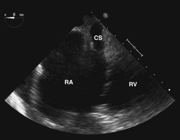
Coronary Sinus
The coronary sinus comes into view when the probe is withdrawn to near the gastroesophageal junction and the flexion knobs are in relatively neutral positions (Fig. 1-14). This view can also be achieved by retroflexion with the probe in the lower esophagus. The coronary sinus is seen as a vascular structure located posterior to the LV at the atrioventricular groove draining into the RA. The tricuspid valve can be visualized to the right and anterior. A dilated coronary sinus should raise the possibility of the presence of a persistent left superior vena cava, which is the most common cause. Leftward rotation while following the coronary sinus may sometimes demonstrate this anomalous vein.23 In the esophageal views, the left superior vena cava is usually sandwiched between the left atrial (LA) appendage and left superior pulmonary vein.24
Aortic Views
The thoracic aorta is well assessed by TEE because of its close proximity to the esophagus.
Descending Thoracic Aorta
The best way to assess the descending thoracic aorta is to use the horizontal imaging plane with the transducer rotated leftward and posterior, followed by slow withdrawal from the level of the diaphragm to the aortic arch (see Fig. 1-1, D).12 Because of the relationship between the esophagus and aorta, slight rotational adjustment is required to visualize the entire circumference of the aortic wall as the probe is slowly withdrawn.24 If the aorta is dilated or tortuous, proper short-axis views of the descending aorta will require adjustment of the imaging plane by 0° to 90°.
Aortic Arch
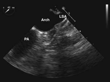
The longitudinal imaging plane at 90° is preferred in imaging the aortic arch because it allows visualization of the entire circumference of the aorta (Fig. 1-15).24 Anterior rotation of the longitudinal plane should visualize the entire aortic arch, but the proximal aortic arch may not be visualized when the aortic arch is unfolded. The transducer will need to be withdrawn slightly to image the arch vessels, which course superiorly. In one third of patients, all three arch vessels can be imaged, but in the other two thirds of patients, only the two distal arch vessels can be imaged. It is rare not to be able to image at least one arch vessel. As a rule, the brachiocephalic artery, which is anterior and more rightward, is the most difficult to image because of the interposing trachea. The transverse plane in a more superior location may sometimes show the three arch vessels in their short axis. Advancing the probe by 1 to 2 cm so that the imaging plane is just inferior to the aortic arch can frequently image the proximal left pulmonary artery. It is sometimes possible to follow it to the first bifurcation. This view should be sought in patients suspected of having pulmonary embolism.
Three-Dimensional Imaging
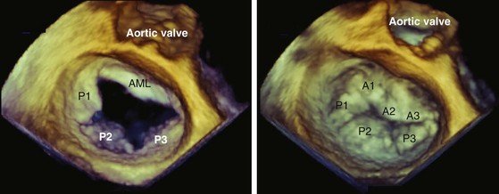
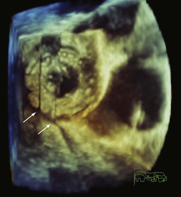
Advances in transducer technology have enabled the incorporation of real-time 3D-imaging capacity into the commercially available TEE probe, such that 3D imaging can be readily performed during a conventional two-dimensional (2D) TEE study providing unique anatomic perspectives in a number of clinical situations.25–32 (See Chapter 4.) The current clinical indications of 3D TEE are summarized in Table 1-2, and the indications are likely to increase with time. In our opinion, 3D TEE imaging should be routinely performed in patients with mitral valve disease and congenital heart disease (Fig. 1-16).
TABLE 1-2 Common Indications for Using Real-time Three-Dimensional Transesophageal Echocardiography
| Cardiac Structure | Information from 3D TEE | Clinical Situations |
|---|---|---|
| Mitral valve | En-face view of mitral valve | Assessment of the location of prolapsing or flail mitral leaflet scallops for potential mitral valve repair; intraoperative assessment of mitral valve clip repair. |
| Prosthetic valve | Number, size, and location of perivalvular regurgitant jets | Preoperative and intraoperative assessment for device closure of perivalvular regurgitation |
| Atrial septum | Number, size, and location of atrial septal defect | Preoperative and intraoperative assessment for device closure of atrial septal defect |
| Intracardiac baffle or conduit | Better anatomic perspective of intracardiac abnormalities | Assessment of naïve and postoperative complex congenital heart disease |
The currently available 3D TEE probe can perform 3D imaging in several modes: 3D full volume, 3D zoom, 3D live, 3D color-flow imaging, and X-plane imaging. We find 3D zoom and X-plane imaging to be the most useful. To acquire 3D full volume, the full pyramidal volume is obtained by stitching together four subvolumes gated to the R-wave of the electrocardiogram. To minimize the stitch artifact between the subvolumes, it is best to acquire the images during a breath hold (Fig. 1-17). In this mode, frame rates are relatively low. Although analysis of the volumetric data set can be performed online, it is frequently performed offline so as not to prolong the study. In the full-volume mode, the semiautomatic multiple parallel slice display can be a quick and useful format in the assessment of LV topography, such as in patients with regional wall motion abnormalities or ventricular aneurysms.
In the real-time live 3D mode, the 3D data set is displayed in real time. It is important to minimize the sector angle so as to increase the frame rate, which is considerably reduced compared to 2D imaging. We find the 3D zoom mode to be the most versatile. In the 3D zoom mode, the area of interest is identified and encompassed by the zoom box, generally in two orthogonal planes. The height and width of the zoom box are adjusted to include the entire area of interest and at the same time streamlined as much as possible in order to enhance the frame rate. Indeed, the 3D zoom mode is our preferred display format when using the 3D live mode. The availability of the X-plane is a very welcome addition to TEE imaging. It allows the simultaneous display of an additional plane during standard 2D imaging. The orientation of the additional plane is usually orthogonal but can be easily adjusted to any specific orientation. The availability of the X-plane provides a quick and comprehensive assessment of complex structures. One example is the LA appendage, which frequently has multiple lobes (see Fig. 1-8). The use of the X-plane allows rapid assessment of the multiple lobes. Similarly, when multiple mitral regurgitant jets are present, X-plane imaging can readily identify the number and orientations of the regurgitant jets.
Real-time 3D color flow imaging can also be performed to provide a 3D assessment of the color flow jet, but the volume of interest is small, and the frame rate is quite limited in this mode.33,34 In vitro and early clinical studies have suggested that 3D color flow imaging gives a more accurate assessment of the shape and size of the vena contracta and flow convergence, both of which are important measures of mitral regurgitation severity. Its clinical usefulness, however, remains unclear.
In order to obtain a high-quality 3D image, the 2D image needs to be optimized in terms of gain and compression settings. A slightly higher gain setting generally provides better 3D images. In both the 3D zoom and 3D live modes, the zoom box should be streamlined to focus on the area of interest to maximize the frame rate. Because the best 3D imaging is obtained with the structure close to the transducer and orthogonal to the ultrasound beam, the TEE transducer should be manipulated to achieve these two objectives. For instance, the transgastric window is superior to the transesophageal window in 3D imaging of the LV papillary muscles. The mitral valve is well suited for 3D TEE imaging precisely for these reasons (see Fig. 1-16). On the other hand, it is much more difficult to obtain a good 3D image of the aortic valve because the valve plane is frequently parallel to the ultrasound beam.
Doppler Examination
Transesophageal echocardiography can be used to assess the flow patterns across the four cardiac valves, but it does not provide additional information to transthoracic echocardiography (TTE). Furthermore, good ultrasound beam alignment with the transvalvular flow may not be feasible because of the anatomic confines of the esophagus. However, accurate Doppler assessment of aortic stenosis can often be obtained from the transgastric window (see Fig. 1-12).22 On the other hand, intracardiac flows such as pulmonary vein flow and LA appendage flow are better and more consistently obtained by TEE and provide important insight into intracardiac hemodynamics.
Left Atrial Appendage Flow
The pattern of LA appendage flow is dependent on cardiac rhythm.35,36 In atrial fibrillation, a regular atrial contraction wave is absent. (See Chapter 42.) In atrial flutter, the velocity waves are more regular and tend to be of greater velocity because of the slower atrial rate. The normal LA appendage velocities are as follows: contraction, 60 ± 14 cm/s; filling, 52 ± 13 cm/s; and early diastolic filling, 20 ± 11 cm/s.35,37
The potential clinical utility of measuring LA appendage velocities relates to their association with LA spontaneous echo contrast and LA thrombus.35,36,38,39 Patients with atrial fibrillation and a LA appendage emptying velocity less than 20 cm/s are more likely to have LA thrombus and have a 2.6-fold greater risk of ischemic stroke compared to patients with a velocity greater than 20 cm/s.38,39 Lower LA appendage velocities have also been observed in stroke patients in normal sinus rhythm.40 LA appendage velocities may predict successful cardioversion of atrial fibrillation41 and the maintenance of sinus rhythm at 1 year.35,36,42
Pulmonary Vein Flow
Pulmonary venous flow patterns provide unique and ancillary information for evaluating LV diastolic function, measuring LV filling pressure, assessing mitral regurgitation severity, differentiating constrictive pericarditis from restrictive cardiomyopathies, and identifying pulmonary vein stenosis after radiofrequency ablation of atrial fibrillation.43–45 TTE can obtain pulmonary vein flow in up to 90% of patients; however, TEE allows a more consistent and reliable acquisition of high-quality laminar Doppler signals.43,46
Indications for Transesophageal Echocardiography
TEE can also visualize cardiac structures not usually seen by TTE (i.e., the superior vena cava, pulmonary veins, and descending thoracic aorta) and can provide improved anatomic and spatial resolution to both diagnose cardiac pathology and guide patient management. Common clinical indications for TEE are listed in Box 1-2.
Box 1-2 Common Indications For Transesophageal Echocardiography
Nondiagnostic transthoracic echocardiogram
Evaluation of native valve disease
Evaluation of prosthetic valves
Evaluation of suspected and definite infective endocarditis
Evaluation of a suspected cardioembolic event
Evaluation of cardiac tumors or masses
Evaluation of an atrial septal abnormality
Evaluation of an acute aortic syndrome or aortic disease
Atrial fibrillation (TEE-guided strategy for “early” cardioversion)
Evaluation of naïve and surgically corrected congenital heart disease
Detection of coronary artery anomalies and coronary artery disease
Evaluation of postoperative cardiac tamponade and pericardial disease
Native Valve Disease
The close proximity of the mitral valve to the posteriorly positioned TEE transducer allows excellent visualization of the mitral annulus, leaflets, chordal structures, and papillary muscles. (See Chapters 18 and 19.) Ruptured chordae tendinae can be visualized, and prolapsing or flail scallops can be localized, to predict the potential for successful mitral valve repair.20,47–49 Abnormalities of the papillary muscles, such as a partial or complete rupture, are better visualized by TEE than TTE.50 3D TEE provides superior delineation of the mitral valve anatomy and can more precisely characterize and localize mitral valve pathology compared to 2D TEE.26,30,31,51
The severity of mitral valve regurgitation can be quantified by TEE using the same methods employed for TTE52; however, color Doppler regurgitant jet areas tend to be larger on TEE than on TTE.53 3D color Doppler imaging provides additional information on the mechanism and severity of mitral regurgitation that may not be apparent from 2D TEE.33,51,54,55 Pulmonary vein flow can be assessed in nearly all patients and provides a valuable measure of mitral regurgitation severity.43,56 The vena contracta width and regurgitant orifice area, derived by the proximal flow convergence method, can be measured using TEE and can provide prognostic information in patients with asymptomatic mitral regurgitation.57–59 The accuracy of these latter measures to quantify mitral regurgitation severity can be improved using 3D TEE.33,55
In mitral stenosis, TEE can assess valve mobility and leaflet thickening, but subvalvular disease and calcification may be underestimated in the esophageal views due to a shadowing effect from the thickened and calcified mitral valve leaflets and annulus.60 (See Chapter 21.) Effective orifice area can be derived by the pressure half-time method, proximal flow convergence method, or orifice planimetry.61,62 Accurate orifice planimetry requires a tomographic cut of the distal, most narrowed portion of the mitral orifice. Optimal alignment of the image is frequently not possible using 2D TEE, but may be achievable by 3D TEE.31 The suitability of a patient for percutaneous balloon mitral valvuloplasty usually incorporates a TEE evaluation of the LA chamber and appendage to identify thrombus, an assessment of the mitral valve morphology score, and an evaluation of mitral regurgitation severity. Mitral valve morphology on TEE is predictive of the prognosis of patients following percutaneous balloon mitral valvuloplasty; however, TTE is preferred to evaluate valve morphology because of the limitations of TEE in evaluating calcification and subvalvular thickening.60,63 TEE can be used during transcatheter mitral commissurotomy to guide the transseptal puncture and balloon placement and to identify potential procedural complications (i.e., severe mitral regurgitation, cardiac tamponade, or significant atrial septal defect).64 (See Chapter 5.) 3D TEE may provide incremental information during the procedure by confirming the coaxial trajectory of the balloon through the stenotic mitral valve and by better evaluating commissural opening postdilation.65,66
Subaortic membranes frequently require TEE for definitive diagnosis.67 Anatomic valve area of a stenotic aortic valve can be measured using multiplane TEE by planimetry of the maximum systolic orifice area in the esophageal short-axis (30° to 60°) view.22,68 Proper transducer position should be confirmed by rotating to the longitudinal plane and verifying that the leaflet tips are being imaged. However, dynamic movements of the aortic valve can cause misalignment of the imaging plane with the narrowest cross-sectional area and result in an inaccurate measurement of the anatomic valve area. 3D TEE can avoid this potential pitfall.69 Unfortunately, valve calcification can affect the accuracy of TEE-measured orifice areas using either 2D or 3D techniques.70
TEE is rarely necessary to evaluate aortic regurgitation severity. The standard methods used during TTE to quantify aortic regurgitation severity can be used during TEE.52,71 Color jet areas on TEE tend to be larger than those obtained during TTE.53 Vena contracta width on TEE correlates well with the regurgitant fraction and regurgitant volume.72 Aortic regurgitation severity can also be quantified using the proximal flow convergence method.73 Holo-diastolic flow reversal in the descending aorta can be detected by TEE using pulsed Doppler.74
The tricuspid and pulmonic valves can be visualized on TEE; however, TTE generally provides better visualization because of the anterior position of these valves. 3D TEE appears to be of limited value in evaluating these valves. In one study, 3D TEE provided optimal visualization of the tricuspid valve in only 11% of patients.75 However, TEE may provide clinically relevant information about the tricuspid and pulmonic valves in patients with poor TTE images.
Prosthetic Valves
TEE is more sensitive for detecting abnormalities of bioprosthetic and mechanical prostheses when compared to TTE.76 (See Chapter 25.) Leaflet thickening and calcification, flail leaflets, vegetations, thrombi, filamentous strands, and motion of the occluding device are better appreciated on TEE.76–83 TEE can distinguish pannus from thrombus formation and guide the use of thrombolytic therapy.84–87 TEE is especially valuable in assessing a mitral prosthesis, because the transducer’s posterior position provides excellent visualization of vegetations and thrombi that usually locate on the LA aspect of the prosthesis.76,78 However, the ventricular aspect of a mitral prosthesis may not be adequately seen on TEE, and TTE should be performed to complete the assessment.88 3D TEE can provide excellent visualization of a mitral prosthesis ring, leaflets, or strut (mechanical or bioprosthesis).27 The aortic prosthesis ring can also be well seen on 3D TEE; however, visualization of the leaflets can be suboptimal.27
TEE should be performed if significant prosthetic mitral regurgitation is suspected clinically, but not seen on TTE. TEE can distinguish normal variant from pathological prosthetic valve regurgitation and determine whether the regurgitation is paravalvular or transvalvular in origin, potentially modifying the surgical procedure.77–8089 3D TEE may provide better delineation of the site and extent of paravalvular regurgitation or mitral prosthesis dehiscence compared to 2D TEE.27 The incremental benefit of TEE in assessing prosthetic aortic regurgitation severity is less clear, because the regurgitant jet is usually well seen on TTE, and TEE visualization may be compromised by partial shadowing of the regurgitation jet by either the aortic or mitral prosthesis when imaged in the esophageal views.80
All bioprostheses and mechanical prostheses are inherently stenotic, the severity dependent on the prosthesis type and size and the presence of associated pathology such as leaflet calcification, pannus formation, or valve thrombosis. In general, TTE is sufficient to assess the hemodynamic severity of a stenotic aortic or mitral prosthesis, but only TEE has sufficient resolution to distinguish these pathologic conditions.84,85 In patients with an inadequate TTE, TEE can be used to quantify the stenosis severity, as described for native valve stenoses.22,62,68,90
Infective Endocarditis
Identification of a vegetation in the clinical setting of suspected endocarditis confirms the diagnosis.91 Studies comparing TTE and TEE for detecting a vegetation in native valve endocarditis report a sensitivity of 28% to 70% for TTE, substantially lower than the 86% to 100% sensitivity reported for TEE.92–97 (See Chapter 22.) Smaller vegetations are better detected by TEE because of the improved spatial resolution of this technique.93 However, TTE and TEE have a similar specificity that exceeds 90% when strict criteria for diagnosing a vegetation are used.92,93,95,97 Pulmonic valve vegetations are better detected by TEE than TTE, despite the anterior position of the pulmonic valve.98 In contrast, TEE has not been reported to have a better sensitivity for detecting tricuspid valve vegetations compared to TTE.99 However, we would recommend a TEE if there is a clinical suspicion of tricuspid valve endocarditis but the TTE is negative.
Prosthetic valve endocarditis is more difficult to diagnose by either TTE or TEE. The sensitivity of TTE for detecting vegetations ranges from 0% to 43% and increases to 33% to 86% using TEE.76,94,100,101 Clearly, TEE can identify a vegetation in a significant number of patients with a negative TTE and should be performed in patients with suspected prosthetic valve endocarditis if the TTE does not identify a vegetation.102
Although TEE provides a greater sensitivity than TTE for detecting vegetations in native and prosthetic-valve endocarditis, TEE has the greatest impact on diagnosis in patients with suspected endocarditis and an intermediate clinical probability of endocarditis.102,103 The absence of a vegetation on TEE in this setting makes the diagnosis of endocarditis unlikely (less than 10%), and alternative diagnoses should be considered.101,104 However, a negative TEE does not supplant a clinical and microbiological diagnosis, because false-negative studies have been reported. Patients with a negative TEE study may benefit from a follow-up TEE in 7 to 10 days if there is a high index of suspicion of endocarditis, a prosthetic valve, or persistent bacteremia.101–104 TEE is likely not warranted in patients with a low clinical probability of endocarditis, because the diagnostic yield is small.103
Complications of infective endocarditis, including abscess formation, leaflet diverticula, leaflet perforation, fistula tracts, mycotic aneurysms, and pseudoaneurysm formation, are significantly better detected by TEE than TTE.94,105–108 TTE has a low sensitivity (less than 30%) for detecting an abscess,105 so a patient with a suspected abscess on clinical grounds or persistent bacteremia should undergo TEE despite a negative TTE. TEE can be falsely negative in up to half of patients with an abscess.108 This often occurs when the abscess cavity is localized on the posterior aspect of a calcified mitral annulus or when a prosthesis is present.108
The potential utility of TEE in uncomplicated confirmed endocarditis remains to be defined. Large (greater than 10 to 15 mm) or severely mobile vegetations on TEE are associated with systemic embolization, and vegetation size is an independent predictor of survival.96,109,110 Furthermore, complications are more likely to occur in patients in whom a vegetation fails to decrease in size with therapy.111 Although we routinely perform a TTE in follow-up of patients with uncomplicated confirmed endocarditis to reevaluate vegetation size and valve function, we do not routinely perform a follow-up TEE.
Suspected Cardioembolic Event
Cardiogenic embolism accounts for approximately 15% to 30% of ischemic strokes and should be considered as a potential cause of cerebral ischemia, especially in those patients without significant cerebrovascular disease.112 (See Chapter 41.) Potential cardioembolic sources encompass conditions that have a propensity for thrombus formation, intracardiac or intraaortic masses, and potential passageways for paradoxical emboli. Cardiac abnormalities having a strong association with cardioembolic events include atrial fibrillation, LA or LV thrombi, vegetations, intracardiac tumor, mitral stenosis, mechanical valves, recent myocardial infarction, dilated cardiomyopathy, ischemic LV dysfunction (ejection fraction less than 28%), and intraaortic debris.113,114 Minor risk sources with weaker associations include atrial septal aneurysms, patent foramen ovale, spontaneous echo contrast, mitral annular calcification, mitral valve prolapse, and calcified aortic stenosis.113–115 Although many of these conditions can be diagnosed clinically, echocardiography is frequently necessary to diagnose anatomic abnormalities.116 In general, TEE is superior to TTE at identifying major and minor risk sources.
LA thrombus is usually located in the LA appendage, a region poorly visualized on TTE. TTE has a sensitivity for detecting LA thrombi of only 0% to 53%, whereas TEE has a sensitivity of 93% to 100% and a specificity exceeding 95%.117,118 Care must be taken not to mistake the pectinate muscles for LA appendage thrombus. LA spontaneous echo contrast is rarely appreciated on TTE but is well seen on TEE. LV thrombi can usually be detected by TTE (sensitivity and specificity approaching or exceeding 90%), and contrast echocardiography can improve the diagnostic accuracy.119 In general, TEE adds no incremental sensitivity unless the TTE is inconclusive, because the apex is located in the far-field position and apical foreshortening is common.120,121 TEE may better detect small myxomas or papillary fibroelastomas.122,123 Similarly, TEE is superior to TTE for detecting an atrial septal aneurysm and patent foramen ovale, although the addition of harmonic imaging to TTE has improved the sensitivity of TTE for detecting a patent foramen ovale.124–126 The cardioembolic risk of a patent foramen ovale is related to the defect size, which can be better appreciated by TEE.127,128 Aortic arch atheroma can be detected by TTE; however, TEE is required to adequately assess the extent, degree of lumen protrusion, and morphological features (i.e., mobility, ulceration, calcification) that characterize the potential embolic risk.38,129–131
The indication for performing a TEE in a patient with a suspected cardioembolic event is controversial.113,132,133 Although TEE has a better sensitivity than TTE for detecting potential cardioembolic sources,134,135 the yield for identifying a major risk source is limited. An analysis of pooled data suggested an overall detection rate for intracardiac masses of only 4% for TTE and 11% for TEE.113 The yield was greater in patients with cardiac disease (TTE, 13%; TEE, 19%), but small in patients without cardiac disease (TTE, 0.7%; TEE, 1.6%). Of importance, the identification of minor risk source by TEE may not significantly alter patient management. Therefore, TEE should only be performed if the results have a reasonable chance of altering patient management or therapy. In this regard, TEE likely has the greatest potential impact on management when the TTE fails to identify a cardioembolic source in a patient with (1) unexplained cerebral ischemia before 55 years of age, (2) recurrent events or events in multiple cerebrovascular territories, (3) occlusion of a large peripheral or visceral artery, or (4) suspected endocarditis.
Atrial Septal Abnormalities
Atrial septal defects, atrial septal aneurysms, and patent foramen ovale are identified more frequently by TEE than TTE.14,124,126 Sinus venosus defects and associated anomalous pulmonary venous drainage are easily detected on TEE, but frequently missed on TTE.14,15 Therefore, a TEE should be considered in a patient with unexplained right heart dilation despite a negative TTE for intracardiac shunting. (See Chapter 44.) TEE can delineate the morphological details of an atrial septal defect and patent foramen ovale, determine the size of the defect and severity of left-to-right shunting, determine the potential for percutaneous closure, and assist with proper device placement during percutaneous closure.32,127,128,136,137 The en-face view of the atrial septum using 3D TEE and multiplanar reconstruction provides a better appreciation of the defect (i.e., size, presence of multiple defects, septal rim length) and spatial relationships among the defect, occluding device, and surrounding cardiac structures such as the mitral valve and aortic root.32,75,138,139
Cardiac Tumors
The sensitivity of TTE and TEE for detecting atrial myxomas has been reported to be 95% and 100%, respectively.140 (See Chapter 46.) Similar high sensitivities have been reported when detecting nonmyxomatous intracardiac tumors.140 However, the sensitivities of TTE and TEE are dependent on tumor size and may be as low as 62% and 77%, respectively, for detecting papillary fibroelastomas smaller than 2 mm.123 TEE is superior to TTE for characterizing features of an intracardiac tumor that are important for diagnosis and management, such as the involvement of multiple chambers, site of attachment, presence of multiple tumors, infiltration of adjacent structures, and presence of tumor calcification or cyst formation.122,140 TEE can be used to guide percutaneous biopsy of an intracardiac tumor.141 3D TEE may provide incremental information relevant to deciding the optimal surgical approach.142
Pericardial or paracardial tumors are better detected using TEE than TTE.140 TEE appears especially valuable for detecting tumors located at the base of the heart, adjacent to the great vessels, or adjacent to the right heart.122,140 However, the size and extent of paracardial involvement is not usually well delineated using TTE or TEE. Magnetic resonance imaging and computed tomography have a wider field of view and provide a superior evaluation of extracardiac involvement.
Acute Aortic Syndromes
Aortic dissection can be detected by TEE with a high degree of accuracy and is the diagnostic investigation of choice for suspected aortic dissection in many institutions.143 (See Chapter 36.) The presence of an intimal flap is diagnostic of aortic dissection and can be distinguished from reverberation artifacts commonly seen in the ascending aorta by using M-mode echocardiography.144 A small segment of the superior ascending aorta may not be visualized by TEE because of the interposition of the air-filled trachea and bronchus. Multiplane TEE has a sensitivity of 98% to 100% and a specificity of 94% to 95%145 and can be performed at the bedside of hemodynamically unstable patients. TEE can determine the extent of the dissection and involvement of arch vessels or coronary arteries, differentiate the true and false lumen, identify thrombus within the false lumen, locate the site of the intimal tear, detect signs of rupture, and evaluate for aortic valve involvement and the potential for valve repair.143,146 TEE can also guide stent graft implantation for descending thoracic aorta dissections and identify complications following surgical repair.147,148
Intramural hematoma and penetrating aortic ulcers have a similar presentation to aortic dissection.149,150 TEE has a sensitivity and specificity that exceed 90% for identifying intramural hematoma145 and can be performed serially to assess for hematoma regression or progression or the development of classic dissection.151 The diagnostic accuracy of TEE for detecting penetrating aortic ulcers is unclear; however, one study reported a sensitivity of 83%.152 The presence, depth, and diameter of a penetrating ulcer are predictive of disease progression and prognosis.153
Traumatic aortic rupture and blunt aortic trauma can be diagnosed by TEE with a sensitivity of 63% to 100% and a specificity of 84% to 100%.130,154 TEE can guide the acute management and triage patients for conservative therapy, immediate surgery, or postponed surgical repair.155 However, TEE cannot consistently visualize the superior ascending aorta and aortic arch branch vessels, a frequent site of traumatic injury.
Atrial Fibrillation
Atrial fibrillation predisposes the LA to contractile dysfunction, chamber dilation, and thrombus formation in approximately 13% of patients with nonrheumatic atrial fibrillation of more than 2 days’ duration.156 TEE is clearly superior to TTE for detecting LA thrombus and has a sensitivity ranging from 93% to 100% and a specificity greater than 95%.117,118 In addition, LA appendage velocity less than 55 cm/s on TEE identifies patients at increased risk for thrombus formation.157 The presence of LA thrombus, spontaneous echo contrast, LA appendage velocity below 20 cm/s, or complex aortic atheroma on TEE identifies patients with atrial fibrillation at higher risk of thromboembolism.38,158
A TEE-guided strategy can be used in patients with atrial fibrillation of more than 2 days’ duration to permit “early” cardioversion without a preceding 3 weeks of therapeutic anticoagulation.159 (See Chapter 42.) This approach provides a therapeutic option for patients at increased risk of a hemorrhagic complication with anticoagulation therapy or who are not tolerating their atrial fibrillation. In the TEE-guided approach, LA thrombus is ruled out by TEE and followed by “early” cardioversion. The TEE-guided strategy had a similar incidence of embolic events, stroke, or transient ischemic attack, but fewer hemorrhagic events, compared to the conventional management strategy.159 The costs of the two strategies are similar.160
LA appendage velocity may predict the likelihood of maintaining sinus rhythm post cardioversion41,42; however, we do not perform TEE studies in patients with atrial fibrillation solely for this purpose.
Congenital Heart Disease
The potential indications for TEE in patients with congenital heart disease are extensive and encompass the preoperative, interventional, intraoperative, and postoperative management of these patients.161–163 (See Chapters 43–45.) TEE better appreciates abnormalities of the atrial septum and pulmonary veins.14,15,32,75,137,162 The atrioventricular valves and site of chordal insertion are better visualized using TEE if surgical valvuloplasty is being considered for an atrioventricular canal defect.164 TEE can better appreciate a baffle stenosis or leak, or complication of a Fontan procedure such as obstruction or thrombosis.165,166 TEE can characterize outflow tract obstructions67,162 or abnormalities of the aorta, such as aortic coarctation or a patent ductus arteriosus.167,168 3D TEE provides incremental information beyond 2D TEE, including a better delineation of the shape of an intracardiac defect, anatomic position, extent of an atrial rim, and potential presence of multiple or fenestrated defects.32,139,169,170
Coronary Artery Disease
Stress echocardiography with TTE imaging is a widely used technique for evaluating patients with suspected or confirmed coronary artery disease, and the addition of a contrast agent can improve the diagnostic accuracy when endocardial definition is limited.171,172 (See Chapters 15 and 16.) In specific clinical situations, TEE can be used to diagnose coronary artery disease by either (1) visualizing coronary stenoses in the proximal vessels, or (2) detecting stress-induced regional wall motion abnormalities.
The left main coronary artery can be visualized in more than 85% of patients using TEE. The proximal left anterior descending artery and left circumflex artery can also be visualized in most patients. The proximal right coronary artery is more difficult to visualize but may be seen in more than 50% of patients. In patients with visualized vessels, TEE has a sensitivity and specificity of greater than 90% for identifying a significant left main coronary artery stenosis.173,174 The sensitivity of TEE for detecting significant proximal disease in the left anterior descending artery, left circumflex artery, or right coronary artery is 78% to 100%, 50% to 89%, and 82% to 100%, respectively, but significantly decreases when nonvisualized segments are included in the analysis.173,174 However, TEE should not replace coronary angiography in the diagnosis of proximal coronary artery disease, but rather should be potentially used when an angiographic stenosis of the left main or left anterior descending artery is of questionable severity and intravascular ultrasound is unavailable.175
Stress TEE can be performed using either transesophageal atrial pacing or pharmacologic stimulation with dobutamine or dipyridamole infusion. These techniques are accurate in detecting and risk-stratifying patients with coronary artery disease and can be performed safely in morbidly obese patients.176–179 However, TEE is an invasive procedure with potential risks and should be reserved for patients with poor TTE images.
Additional applications of TEE include the detection of anomalous coronary arteries, coronary artery aneurysms, and coronary artery fistulas.173
Pericardial Disease
Cardiac tamponade can be challenging to diagnose early after cardiac surgery. (See Chapter 29.) Localized compression of a cardiac chamber (usually the RA) may not be apparent on TTE because the thrombus is located posteriorly; image quality is poor because of suboptimal patient positioning, surgical bandages, and drainage tubes; and the findings of RA or RV diastolic collapse are frequently absent. TEE circumvents many of these problems and can better detect extracardiac compression.180 In constrictive pericarditis, TEE with respiratory monitoring can be helpful in patients with a nondiagnostic TTE.181,182 Pericardial thickening, pericardial metastases, intrapericardial thrombus, and pericardial cysts are better seen by TEE than TTE.180,183 However, computed tomography and magnetic resonance imaging are better techniques for evaluating pericardial thickness, pericardial calcification, localized pericardial abnormalities, and tissue characterization of a pericardial mass.182
Critically Ill Patient In The Intensive Care Unit
TTE image quality in an intensive care unit is frequently inadequate, and in this setting TEE can provide rapid access to diagnostic information that alters patient management.184,185 TEE can evaluate myocardial function, valve function, volume status, hemodynamics, and intracardiac shunting, which are critical components for the diagnosis and management of patients with unexplained hypotension, pulmonary edema, or hypoxia.17,18,184–187
Monitoring During Surgical And Interventional Procedures
A comprehensive intraoperative TEE can evaluate global and segmental LV function; detect intraoperative myocardial ischemia; monitor hemodynamics including cardiac output, LV filling pressures, and volume status; determine the potential cause of hemodynamic disturbances; and evaluate the adequacy of surgical repairs, replacements or reconstructions before leaving the operating room.188 (See Chapter 2.) The American Society of Anesthesiologists and the Society of Cardiovascular Anesthesiologists recently updated their guidelines on the use of perioperative TEE, recommending that intraoperative TEE be used in all open heart and thoracic aorta surgical procedures and be considered during coronary artery bypass graft surgery.163 Intraoperative TEE was recommended during noncardiac surgery when the patient has known or suspected cardiovascular pathology that might result in hemodynamic, pulmonary, or neurologic compromise.163
TEE is routinely used during percutaneous closure of an atrial septal defect or patent foramen ovale to exclude multiple defects, size the defect, guide positioning of the occluding device, and determine the presence of residual shunting.137,170 (See Chapter 5.) 3D TEE can provide additional information relevant to the procedure.32,170 Percutaneous closure of a ventricular septal defect is usually performed under 2D or 3D TEE guidance.32,170 During percutaneous mitral valvuloplasty, TEE can direct the transseptal puncture, assist with proper balloon placement, evaluate the result, identify any complications, and shorten procedure and fluoroscopy times.189 For transcatheter aortic valve implantation, TEE can guide proper prosthesis positioning and identify periprocedural complications.190 During transcatheter closure of a periprosthetic valve leak, TEE can delineate the precise location and extent of any paravalvular jets.170 3D TEE can improve spatial appreciation of the regurgitant jets (i.e., number, location, extent), better identify complications, and improve procedural efficiency.27,33 TEE can assist with the proper positioning of a LA appendage occluding device, which is essential to avoid complications.32 TEE has also been used to guide catheter ablation of arrhythmias, alcohol septal ablation for hypertrophic cardiomyopathy, and biopsy of the RV or an intracardiac mass.32,141
Contraindications to Transesophageal Echocardiography
There are few absolute contraindications to performing a TEE (Box 1-3); however, relative contraindications are more frequently encountered in clinical practice. Thus, a critical analysis of the risk-benefit ratio is required based on available information and potential discussion with the attending physician.
An elective TEE should be postponed if the patient has not been fasting for 4 to 6 hours before the procedure because of the risk of vomiting and aspiration. However, an urgent TEE can be performed with minimal risk of vomiting and aspiration if only clear fluids were taken up to 2 hours before the procedure.191 TEE should not be performed in an uncooperative patient who is not heavily sedated or paralyzed to minimize the chance of injury. Patients with a tenuous cardiorespiratory status should be intubated and ventilated to avoid decompensation during the procedure. TEE should not be attempted in a patient with an esophageal obstruction (stricture or mass) because of the potential for esophageal rupture. Upper endoscopy should be considered before performing a TEE if the patient has a history of dysphagia or odynophagia. An esophageal diverticulum is a relative contraindication to TEE because the probe can potentially enter and perforate the diverticulum. Fluoroscopic balloon guidance or a fiberoptic endoscope and overtube can be used to allow a TEE examination in the presence of a Zenker diverticulum.192 TEE should not be performed in patients with an unrepaired tracheoesophageal fistula, esophagectomy, perforated viscus, or active gastrointestinal bleed. A history of esophageal varices is not an absolute contraindication to TEE; however, the small risk of major bleeding needs to be weighed against the potential for important incremental information. A severe coagulopathy is a relative contraindication to TEE; however, TEE can safely be performed in patients on anticoagulation therapy. Severe cervical arthritis or dislocation of the atlantoaxial joint, where neck flexion is severely limited, is a relative contraindication.
Complications of Transesophageal Echocardiography
TEE is a relatively safe procedure with a low risk of serious complications. In up to 1.9% of TEE studies, the esophagus cannot be successfully intubated.193 Procedural complications occur in up to 3.5% of patients and predominantly involve the gastrointestinal, cardiovascular, or respiratory systems.193 The vast majority of complications are minor (Box 1-4), with approximately 0.2% to 0.5% of patients suffering a major complication.5,9,193,194 TEE-related mortality has been estimated at less than 0.01%.194 A recent review of 17 studies encompassing 42,355 patients identified four TEE procedural deaths.193
Box 1-4 Procedural Complications With Transesophageal Echocardiography
Perforation of the esophagus and major upper gastrointestinal bleeding are serious gastrointestinal complications that occur in up to 0.01% and 0.03% of TEE studies, respectively.194 Minor gastrointestinal complications include lip and pharyngeal bleeding due to mucosal trauma and excessive retching or vomiting that can require premature termination of the examination.9 Dental injuries occur in up to 0.03% of patients.194 A minor sore throat may be present for 24 hours after the procedure. Approximately 0.1% of patients have persistent odynophagia that requires further investigation.194
Cardiac complications are rare and include nonsustained and sustained supraventricular tachycardias or atrial fibrillation, nonsustained and sustained ventricular tachycardia, bradycardia, transient hypotension or hypertension, angina pectoris, congestive heart failure, and pulmonary edema.193,194
Respiratory complications include laryngospasm (less than 0.02%), accidental tracheal intubation, transient hypoxia, and blood-tinged sputum.193,194
Adverse reactions may occur from intravenous sedation or topical anesthesia. Intravenous sedation can cause respiratory depression, hypoxia, hypotension, or paradoxical reactions. Topical anesthesia with benzocaine or lidocaine can cause acute toxic methemoglobinemia, a rare but potentially lethal condition that manifests clinically in approximately 0.115% of TEE studies.195 In this condition, the topical anesthesia agent oxidizes hemoglobin and prevents oxygen delivery to the tissues, potentially resulting in cyanosis, lethargy, tachycardia, dyspnea, and death.195–197 Methylene blue administration is indicated if the methemoglobin levels are above 30%, or if the patient has cyanosis, central nervous system depression, or cardiopulmonary compromise.195
Intraoperative TEE has a morbidity rate of 0.2% to 1.2%, similar to that reported in the nonoperative setting.194 The complication rates for TEE in pediatric patients are variable.194 The largest case series of predominantly intraoperative TEE reported a complication rate of 2.4% (excluding failed intubations).198


1 Frazin L, Talano JV, Stephanides L, et al. Esophageal echocardiography. Circulation. 1976;54:102-108.
2 Pearlman AS, Gardin JM, Martin RP, et al. Guidelines for physician training in transesophageal echocardiography: recommendations of the American Society of Echocardiography Committee for physician training in echocardiography. J Am Soc Echocardiogr. 1992;5:187-194.
3 Chan K, Burwash I. Unusual structural abnormality in a biplane transesophageal transducer with normal imaging function. J Am Soc Echocardiogr. 1998;11:310-312.
4 Kronzon I, Cziner DG, Katz ES, et al. Buckling of the tip of the transesophageal echocardiography probe: a potentially dangerous technical malfunction. J Am Soc Echocardiogr. 1992;5:176-177.
5 Chan KL, Cohen GI, Sochowski RA, et al. Complications of transesophageal echocardiography in ambulatory adult patients: analysis of 1500 consecutive examinations. J Am Soc Echocardiogr. 1991;4:577-582.
6 Chan K. Impact of transesophageal echocardiography on the management of patients with aortic dissection. Chest. 1991;101:406-410.
7 Steckelberg JM, Khandheria BK, Anhalt JP, et al. Prospective evaluation of the risk of bacteremia associated with transesophageal echocardiography. Circulation. 1991;84:177-180.
8 Melendez L, Chan K, Cheung P, et al. Incidence of bacteremia in transesophageal echocardiography: a prospective study of 140 consecutive patients. J Am Coll Cardiol. 1991;18:1650-1654.
9 Daniel WG, Erbel R, Kasper W, et al. Safety by transesophageal echocardiography: a multicenter survey of 10,419 examinations. Circulation. 1991;83:817-821.
10 Cohen G, Chan K. Biplane transesophageal echocardiography: clinical applications of the long-axis plane. J Am Soc Echocardiogr. 1991;4:155-163.
11 Seward JB, Khandheria BK, Freeman WK, et al. Multiplane transesophageal echocardiography: image orientation, examination technique, anatomic correlations, and clinical applications. Mayo Clin Proc. 1993;68:523-551.
12 Seward JB, Khandheria BK, Oh JK, et al. Transesophageal echocardiography: technique, anatomic correlations, implementation, and clinical applications. Mayo Clin Proc. 1988;63:649-680.
13 Veinot JP, Harrity PJ, Gentile F, et al. Anatomy of the normal left atrial appendage: a quantitative study of age-related changes in 500 autopsy hearts. Implications for echocardiographic examination. Circulation. 1997;96:3112-3115.
14 Kronzon I, Tunick PA, Freedberg RS, et al. Transesophageal echocardiography is superior to transthoracic echocardiography in the diagnosis of sinus venosus atrial septal defect. J Am Coll Cardiol. 1991;17:537-542.
15 Pascoe RD, Oh JK, Warnes CA, et al. Diagnosis of sinus venosus atrial septal defect with transesophageal echocardiography. Circulation. 1996;94:1049-1055.
16 Fagan S, Veinot JP, Chan KL. Residual sinus venosus atrial septal defect following surgical closure of atrial septal defect. J Am Soc Echocardiogr. 2001;14:738-741.
17 Wittlich N, Erbel R, Eichler A, et al. Detection of central pulmonary artery thromboemboli by transesophageal echocardiography in patients with severe pulmonary embolism. J Am Soc Echocardiogr. 1992;5:515-524.
18 Pruszczyk P, Torbicki A, Pacho R, et al. Noninvasive diagnosis of suspected severe pulmonary embolism: transesophageal echocardiography vs spiral CT. Chest. 1997;112:722-728.
19 Shanewise JS, Cheung AT, Aronson S, et al. ASE/SCA guidelines for performing a comprehensive intraoperative multiplane transesophageal echocardiography examination: recommendations of the American Society of Echocardiography Council for Intra-operative Echocardiography and the Society of Cardiovascular Anesthesiologists Task Force for Certification in Perioperative Transesophageal Echocardiography. J Am Soc Echocardiogr. 1999;12:884-900.
20 Enriquez-Sarano M, Freeman WK, Tribouilloy CM, et al. Functional anatomy of mitral regurgitation: accuracy and outcome implications of transesophageal echocardiography. J Am Coll Cardiol. 1999;34:1129-1136.
21 Pieper EP, Hellemans IM, Hamer HP, et al. Additional value of biplane transesophageal echocardiography in assessing the genesis of mitral regurgitation and the feasibility of valve repair. Am J Cardiol. 1995;75:489-493.
22 Blumberg FC, Pfeifer M, Holmer SR, et al. Transgastric Doppler echocardiographic assessment of the severity of aortic stenosis using multiplane transesophageal echocardiography. Am J Cardiol. 1997;79:1273-1275.
23 Catoire P, Beydon L, Delaunay L, et al. Persistent left superior vena cava diagnosed by transesophageal echocardiography. J Cardiothorac Vasc Anesth. 1993;7:375-379.
24 Seward JB, Khandheria BK, Edwards WD, et al. Biplanar transesophageal echocardiography: anatomic correlations, image orientation, and clinical applications. Mayo Clin Proc. 1990;65:1193-1213.
25 Flachskampf FA, Badano L, Daniel WG, et al. European Association of Echocardiography; Echo Committee of the European Association of Cardiothoracic Anaesthesiologists. recommendations for transoesophageal echocardiography: update 2010. Eur J Echocardiogr. 2010;11:557-576.
26 Pepi M, Tamborini G, Maltagliati A, et al. Head-to-head comparison of two- and three-dimensional transthoracic and transesophageal echocardiography in the localization of mitral valve prolapse. J Am Coll Cardiol. 2006;48:2524-2530.
27 Sugeng L, Shernan SK, Weinert L, et al. Real-time three-dimensional transesophageal echocardiography in valve disease: comparison with surgical findings and evaluation of prosthetic valves. J Am Soc Echocardiogr. 2008;21:1347-1354.
28 Saric M, Perk G, Purgess JR, et al. Imaging atrial septal defects by real-time three-dimensional transesophageal echocardiography: step-by-step approach. J Am Soc Echocardiogr. 2010;23:1128-1135.
29 García-Fernández MA, Cortés M, García-Robles JA, et al. Utility of real-time three-dimensional transesophageal echocardiography in evaluating the success of percutaneous transcatheter closure of mitral paravalvular leaks. J Am Soc Echocardiogr. 2010;23:26-32.
30 Kwak J, Andrawes A, Garvin S, et al. 3D transesophageal echocardiography: a review of recent literature 2007-2009. Curr Opin Anaesthesiol. 2010;23:80-88.
31 Vegas A, Meineri M. Three-dimensional transesophageal echocardiography is a major advance for intraoperative clinical management of patients undergoing cardiac surgery: A core review. Anesth Analg. 2010;110:1548-1573.
32 Lee AP, Lam Y, Yip GW, et al. Role of real time three-dimensional transesophageal echocardiography in guidance of interventional procedures in cardiology. Heart. 2010;96:1485-1493.
33 Skaug TR, Hergum T, Amundsen BH, et al. Quantification of mitral regurgitation using high pulse repetition frequency three-dimensional color Doppler. J Am Soc Echocardiogr. 2010;23:1-8.
34 Little SH, Pirat B, Kumar R, et al. Three-dimensional color Doppler echocardiography for direct measurement of vena contracta area in mitral regurgitationin vitro validation and clinical experience. JACC Cardiovasc Imaging. 2008;1:695-704.
35 Agmon Y, Khandheria BK, Gentile F, et al. Echocardiographic assessment of the left atrial appendage. J Am Coll Cardiol. 1999;34:1867-1877.
36 Donal E, Yamada H, Leclercq C, et al. The left atrial appendage, a small, blind-ended structure: a review of its echocardiographic evaluation and its clinical role. Chest. 2005;128:1853-1862.
37 Tabata T, Oki T, Fukuda N, et al. Influence of aging on left atrial appendage flow velocity patterns in normal subjects. J Am Soc Echocardiogr. 1996;9:274-280.
38 The Stroke Prevention in Atrial Fibrillation Investigators Committee on Echocardiography. Transesophageal echocardiographic correlates of thromboembolism in high-risk patients with nonvalvular atrial fibrillation. Ann Intern Med. 1998;128:639-647.
39 Goldman ME, Pearce LA, Hart RG, et al. Pathophysiologic correlates of thromboembolism in nonvalvular atrial fibrillation: I. Reduced flow velocity in the left atrial appendage (The Stroke Prevention in Atrial Fibrillation [SPAFF-III] study). J Am Soc Echocardiogr. 1999;12:1080-1087.
40 Kamalesh M, Copeland TB, Sawada S. Severely reduced left atrial appendage function: A cause of embolic stroke in patients in sinus rhythm? J Am Soc Echocardiogr. 1998;11:902-904.
41 Palinkas A, Antonielli E, Picano E, et al. Clinical value of left atrial appendage flow velocity for predicting of cardioversion success in patients with non-valvular atrial fibrillation. Eur Heart J. 2001;22:2201-2208.
42 Antonielli E, Pizzuti A, Palinkas A, et al. Clinical value of left atrial appendage flow for prediction of long-term sinus rhythm maintenance in patients with nonvalvular atrial fibrillation. J Am Coll Cardiol. 2002;39:1443-1449.
43 Tabata T, Thomas JD, Klein AL. Pulmonary venous flow by Doppler echocardiography: revisited 12 years later. J Am Coll Cardiol. 2003;41:1243-1250.
44 Nishimura RA, Tajik AJ. Evaluation of diastolic filling of left ventricle in health and disease: Doppler echocardiography is the clinician’s Rosetta stone. J Am Coll Cardiol. 1997;30:8-18.
45 Klein AL, Burstow DJ, Tajik AJ, et al. Effects of age on left ventricular dimensions and filling dynamics in 117 normal persons. Mayo Clin Proc. 1994;69:212-224.
46 Jensen JL, Williams FE, Beilby BJ, et al. Feasibility of obtaining pulmonary venous flow velocity in cardiac patients using transthoracic pulsed wave Doppler technique. J Am Soc Echocardiogr. 1997;10:60-66.
47 Agricola E, Oppizzi M, De Bonis M, et al. Multiplane transesophageal echocardiography performed according to the guidelines of the American Society of Echocardiography in patients with mitral valve prolapse, flail, and endocarditis: diagnostic accuracy in the identification of mitral regurgitant defects by correlation with surgical findings. J Am Soc Echocardiogr. 2003;16:61-66.
48 Grewal KS, Malkowski MJ, Kramer CM, et al. Multiplane transesophageal echocardiographic identification of the involved scallop in patients with flail mitral valve leaflet: Intraoperative correlation. J Am Soc Echocardiogr. 1998;11:966-971.
49 Omran AS, Woo A, David TE, et al. Intraoperative transesophageal echocardiography accurately predicts mitral valve anatomy and suitability for repair. J Am Soc Echocardiogr. 2002;15:950-957.
50 Moursi MH, Bhatnagar SK, Vilacosta I, et al. Transesophageal echocardiographic assessment of papillary muscle rupture. Circulation. 1996;94:1003-1009.
51 Salcedo EE, Quaife RA, Seres T, et al. A Framework for systematic characterization of the mitral valve by real-time three-dimensional transesophageal echocardiography. J Am Soc Echocardiogr. 2009;22:1087-1089.
52 Zoghbi WA, Enriquez-Sarano M, Foster E, et al. Recommendations for evaluation of the severity of native valvular regurgitation with two-dimensional and Doppler echocardiography. J Am Soc Echocardiogr. 2003;16:777-802.
53 Smith MD, Harrison MR, Pinton R, et al. Regurgitant jet size by transesophageal compared with transthoracic Doppler color flow imaging. Circulation. 1991;83:79-86.
54 Sugeng L, Spencer KT, Mor-Avi V, et al. Dynamic three-dimensional color flow Doppler: an improved technique for the assessment of mitral regurgitation. Echocardiography. 2003;20:265-273.
55 Shanks M, Siebelink HM, Delgado V, et al. Quantitative assessment of mitral regurgitation: comparison between three-dimensional transesophageal echocardiography and magnetic resonance imaging. Circ Cardiovasc Imaging. 2010;3:694-700.
56 Hynes MS, Tam JL, Burwash IG, et al. Predictive value of pulmonary venous flow patterns in detecting mitral regurgitation and left ventricular abnormalities. Can J Cardiol. 1999;15:665-670.
57 Grayburn PA, Fehske W, Omran H, et al. Multiplane transesophageal echocardiographic assessment of mitral regurgitation by Doppler color flow mapping of the vena contracta. Am J Cardiol. 1994;74:912-917.
58 Pu M, Vandervoort PM, Griffin BP, et al. Quantification of mitral regurgitation by the proximal convergence method using transesophageal echocardiography: Clinical validation of a geometric correction for proximal flow constraint. Circulation. 1995;92:2169-2177.
59 Enriquez-Sarano M, Avierinos JF, Messika-Zeitoun D, et al. Quantitative determinants of the outcome of asymptomatic mitral regurgitation. N Engl J Med. 2005;352:875-883.
60 Marwick TH, Torelli J, Obarski T, et al. Assessment of the mitral valve splitability score by transthoracic and transesophageal echocardiography. Am J Cardiol. 1991;68:1106-1107.
61 Stoddard MF, Prince CR, Tuman WL, et al. Angle of incidence does not affect accuracy of mitral stenosis area calculation by pressure half-time: Application to Doppler transesophageal echocardiography. Am Heart J. 1994;127:1562-1572.
62 Degertekin M, Basaran Y, Gencbay M, et al. Validation of flow convergence region method in assessing mitral valve area in the course of transthoracic and transesophageal echocardiographic studies. Am Heart J. 1998;135:207-214.
63 Levin TN, Feldman T, Bednarz J, et al. Transesophageal echocardiographic evaluation of mitral valve morphology to predict outcome after balloon mitral valvotomy. Am J Cardiol. 1994;73:707-710.
64 Park SH, Kim MA, Hyon MS. The advantages of on-line transesophageal echocardiography guide during percutaneous balloon mitral valvuloplasty. J Am Soc Echocardiogr. 2000;13:26-34.
65 Gill EA, Kim MS, Carroll JD. 3D TEE for evaluation of commissural opening before and during percutaneous mitral commissurotomy. J Am Coll Cardiol Imag. 2009;2:1034-1035.
66 Eng MH, Salcedo EE, Quaife RA, et al. Implementation of real time three-dimensional transesophageal echocardiography in percutaneous mitral balloon valvuloplasty and structural heart disease interventions. Echocardiography. 2009;26:958-966.
67 Essop MR, Skudicky D, Sareli P. Diagnostic value of transesophageal versus transthoracic echocardiography in discrete subaortic stenosis. Am J Cardiol. 1992;70:962-963.
68 Hoffmann R, Flachskampf FA, Hanrath P. Planimetry of orifice area in aortic stenosis using multiplane transesophageal echocardiography. J Am Coll Cardiol. 1993;22:529-534.
69 Nakai H, Takeuchi M, Yoshitani H, et al. Pitfalls of anatomical aortic valve area measurements using two-dimensional transoesophageal echocardiography and the potential of three-dimensional transoesophageal echocardiography. Eur J Echocardiogr. 2010;11:369-376.
70 Cormier B, Iung B, Porte JM, et al. Value of multiplane transesophageal echocardiography in determining aortic valve area in aortic stenosis. Am J Cardiol. 1996;77:882-885.
71 Meyerowitz CB, Jacobs LE, Kotler MN, et al. Assessment of aortic regurgitation by transesophageal echocardiography: Correlation with angiographic determination. Echocardiography. 1993;10:269-278.
72 Willett DL, Hall SA, Jessen ME, et al. Assessment of aortic regurgitation by transesophageal color Doppler imaging of the vena contracta: validation against an intraoperative aortic flow probe. J Am Coll Cardiol. 2001;37:1450-1455.
73 Sato Y, Kawazoe K, Kamata J, et al. Clinical usefulness of the effective regurgitant orifice area determined by transesophageal echocardiography in patients with eccentric aortic regurgitation. J Heart Valve Dis. 1997;6:580-586.
74 Sutton DC, Kluger R, Ahmed SU, et al. Flow reversal in the descending aorta: A guide to intraoperative assessment of aortic regurgitation with transesophageal echocardiography. J Thorac Cardiovasc Surg. 1994;108:576-582.
75 Sugeng L, Shernan SK, Salgo IS, et al. Live 3-dimensional transesophageal echocardiography initial experience using the fully-sampled matrix array probe. J Am Coll Cardiol. 2008;52:446-449.
76 Daniel WG, Mugge A, Grote J, et al. Comparison of transthoracic and transesophageal echocardiography for detection of abnormalities of prosthetic and bioprosthetic valves in the mitral and aortic positions. Am J Cardiol. 1993;71:210-215.
77 Daniel LB, Grigg LE, Weisel RD, et al. Comparison of transthoracic and transesophageal assessment of prosthetic valve dysfunction. Echocardiography. 1990;7:83-95.
78 Khandheria BK, Seward JB, Oh JK, et al. Value and limitations of transesophageal echocardiography in the assessment of mitral valve prosthesis. Circulation. 1991;83:1956-1968.
79 Chaudhry FA, Herrera C, DeFrino PF, et al. Pathologic and angiographic correlations of transesophageal echocardiography in the prosthetic heart valve dysfunction. Am Heart J. 1991;122:1057-1064.
80 Karalis DG, Chandrasekaran K, Ross JJJr, et al. Single-plane transesophageal echocardiography for assessing function of mechanical or bioprosthetic valves in the aortic valve position. Am J Cardiol. 1992;69:1310-1315.
81 Gueret P, Vignon P, Fournier P, et al. Transesophageal echocardiography for the diagnosis and management of nonobstructive thrombosis of mechanical mitral prosthesis. Circulation. 1995;91:103-110.
82 Orsinelli DA, Pearson AC. Detection of prosthetic valve strands by transesophageal echocardiography: Clinical significance in patients with suspected cardiac source of embolism. J Am Coll Cardiol. 1995;26:1713-1718.
83 Muratori M, Montorsi P, Teruzzi G, et al. Feasibility and diagnostic accuracy of quantitative assessment of mechanical prostheses leaflet motion by transthoracic and transesophageal echocardiography in suspected prosthetic valve dysfunction. Am J Cardiol. 2006;97:94-100.
84 Barbetseas J, Nagueh SF, Pitsavos C, et al. Differentiating thrombus from pannus formation in obstructed mechanical prosthetic valves: An evaluation of clinical, transthoracic and transesophageal echocardiographic parameters. J Am Coll Cardiol. 1998;32:1410-1417.
85 Girard SE, Miller FA, Orszulak TA, et al. Reoperation for prosthetic aortic valve obstruction in the era of echocardiography: trends in diagnostic testing and comparison with surgical findings. J Am Coll Cardiol. 2001;37:579-584.
86 Lengyl M. Management of prosthetic valve thrombosis. J Heart Valve Dis. 2004;13:329-334.
87 Tong AT, Roudaut R, Ozkan M, et al. Transesophageal echocardiography improves risk assessment of thrombolysis of prosthetic valve thrombosis: results of the international PRO-TEE registry. J Am Coll Cardiol. 2004;43:77-84.
88 Tenenbaum A, Fisman EZ, Vered Z, et al. Failure of transesophageal echocardiography to visualize a large mitral prosthesis vegetation detected solely by transthoracic echocardiography. J Am Soc Echocardiogr. 1995;8:944-946.
89 Flachskampf FA, Hoffmann R, Franke A, et al. Does multiplane transesophageal echocardiography improve the assessment of prosthetic valve regurgitation? J Am Soc Echocardiogr. 1995;8:70-78.
90 Gorscan JIII, Kenny WM, Diana P, et al. Transesophageal continuous-wave Doppler to evaluate mitral prosthetic stenosis. Am Heart J. 1991;121:911-914.
91 Baddour LM, Wilson WR, Bayer AS, et al. Infective endocarditis: diagnosis, antimicrobial therapy, and management of complications: a statement for healthcare professionals from the Committee on Rheumatic Fever, Endocarditis, and Kawasaki Disease, Council on Cardiovascular Disease in the Young, and the Councils on Clinical Cardiology, Stroke, and Cardiovascular Surgery and Anesthesia, American Heart Association—executive summary: endorsed by the Infectious Diseases Society of America. Circulation. 2005;111:3167-3184.
92 Birmingham GD, Rahko PS, Ballantyne F. Improved detection of infective endocarditis with transesophageal echocardiography. Am Heart J. 1992;123:774-781.
93 Erbel R, Rohmann S, Drexler M, et al. Improved diagnostic value of echocardiography in patients with infective endocarditis by transesophageal approach: A prospective study. Eur Heart J. 1988;9:43-53.
94 Taams MA, Gussenhoven EJ, Bos E, et al. Enhanced morphologic diagnosis in infective endocarditis by transoesophageal echocardiography. Br Heart J. 1990;63:109-113.
95 Shively BK, Gurule FT, Roldan CA, et al. Diagnostic value of transesophageal compared with transthoracic echocardiography in infective endocarditis. J Am Coll Cardiol. 1991;18:391-397.
96 Mügge A, Daniel WG, Frank G, et al. Echocardiography in infective endocarditis: Reassessment of prognostic implications of vegetation size determined by the transthoracic and the transesophageal approach. J Am Coll Cardiol. 1989;14:631-638.
97 Shapiro SM, Young E, De Guzman S, et al. Transesophageal echocardiography in diagnosis of infective endocarditis. Chest. 1994;105:377-382.
98 Ramadan FB, Beanlands DS, Burwash IG. Isolated pulmonic valve endocarditis in healthy hearts: a case report and review of the literature. Can J Cardiol. 2000;16:1282-1288.
99 San Roman JA, Vilacosta I, Zamorano JL, et al. Transesophageal echocardiography in right-sided endocarditis. J Am Coll Cardiol. 1993;21:1226-1230.
100 Zabalgoitia M, Herrera CJ, Chaudhry FA, et al. Improvement in the diagnosis of bioprosthetic valve dysfunction by transesophageal echocardiography. J Heart Valve Dis. 1993;2:595-603.
101 Lowry RW, Zoghbi WA, Baker WB, et al. Clinical impact of transesophageal echocardiography in the diagnosis and management of infective endocarditis. Am J Cardiol. 1994;73:1089-1091.
102 Roe MT, Abramson MA, Li J, Heinle SK, et al. Clinical information determines the impact of transesophageal echocardiography on the diagnosis of infective endocarditis by the Duke criteria. Am Heart J. 2000;139:945-951.
103 Lindner JR, Case RA, Dent JM, et al. Diagnostic value of echocardiography in suspected endocarditis: An evaluation based on the pretest probability of disease. Circulation. 1996;93:730-736.
104 Sochowski RA, Chan KL. Implication of negative results on a monoplane transesophageal echocardiographic study in patients with suspected infective endocarditis. J Am Coll Cardiol. 1994;21:216-221.
105 Daniel WG, Mugge A, Martin RP, et al. Improvement in the diagnosis of abscesses associated with endocarditis by transesophageal echocardiography. N Engl J Med. 1991;324:795-800.
106 de Castro S, Cartoni D, d’Amati G, et al. Diagnostic accuracy of transthoracic and multiplane transesophageal echocardiography for valvular perforation in acute infective endocarditis: Correlation with anatomic findings. Clin Infect Dis. 2000;30:825-826.
107 Tingleff J, Egeblad H, Gotzsche CO, et al. Perivalvular cavities in endocarditis: Abscesses versus pseudoaneurysms? A transesophageal Doppler echocardiographic study in 118 patients with endocarditis. Am Heart J. 1995;130:93-100.
108 Hill EE, Herijgers P, Claus P, et al. Abscess in infective endocarditis: the value of transesophageal echocardiography and outcome: a 5-year study. Am Heart J. 2007;154:923-928.
109 Di Salvo G, Habib G, Pergola V, et al. Echocardiography predicts embolic events in infective endocarditis. J Am Coll Cardiol. 2001;37:1069-1076.
110 Thuny F, Di Salvo G, Belliard O, et al. Risk of embolism and death in infective endocarditis: prognostic value of echocardiography: a prospective multicenter study. Circulation. 2005;112:69-75.
111 Rohmann S, Erhel R, Darius H, et al. Effect of antibiotic treatment on vegetation size and complication rate in infective endocarditis. Clin Cardiol. 1997;20:132-140.
112 Ferro JM. Cardioembolic stroke: an update. Lancet Neurol. 2003;2:177-188.
113 Kapral MK, Silver FL. Preventive health care, 1999 update: 2. Echocardiography for the detection of a cardiac source of embolus in patients with stroke. with the Canadian Task Force on Preventive Health Care. Can Med Assoc J. 1999;161:989-996.
114 Ay H, Furie KL, Singhal A, et al. An evidence-based causative classification system for acute ischemic stroke. Ann Neurol. 2005;58:688-697.
115 Overell JR, Bone I, Lees KR. Interatrial septal abnormalities and stroke: a meta-analysis of case-control studies. Neurology. 2000;55:1172-1179.
116 Pepi M, Evangelista A, Nihoyannopoulos P, et al. Recommendations for echocardiography use in the diagnosis and management of cardiac sources of embolism. Eur J Echocardiogr. 2010;11:461-476.
117 Hwang JJ, Chen JJ, Lin SC, et al. Diagnostic accuracy of transesophageal echocardiography for detecting left atrial thrombi in patients with rheumatic heart disease having undergone mitral valve operations. Am J Cardiol. 1993;72:677-681.
118 Manning WJ, Weintraub RM, Wakomonski CA, et al. Accuracy of transesophageal echocardiography for identifying left atrial thrombi. A prospective intraoperative study. Ann Intern Med. 1995;123:817-822.
119 Senior R, Becher H, Monaghan M, et al. Contrast echocardiography: evidence-based recommendations by European Association of Echocardiography. Eur J Echocardiogr. 2009;10:194-212.
120 Mugge A, Daniel WG, Haverich A, et al. Diagnosis of noninfective cardiac mass lesions by two-dimensional echocardiography: Comparison of the transthoracic and transesophageal approaches. Circulation. 1991;83:70-78.
121 Chen C, Koschyk D, Hamm C, et al. Usefulness of transesophageal echocardiography in identifying small left ventricular apical thrombus. J Am Coll Cardiol. 1993;21:208-215.
122 Mügge A, Daniel WG, Haverich A, et al. Diagnoses of noninfective cardiac mass lesions by two-dimensional echocardiography: Comparison of the transthoracic and transesophageal approaches. Circulation. 1991;83:70-78.
123 Sun JP, Asher CR, Yang XS, et al. Clinical and echocardiographic characteristics of papillary fibroelastomas. A retrospective and prospective study in 162 patients. Circulation. 2001;103:2687-2693.
124 Siostrzonek P, Zangeneh M, Gössinger H, et al. Comparison of transesophageal and transthoracic contrast echocardiography for detection of a patent foramen ovale. Am J Cardiol. 1991;68:1247-1249.
125 Clarke NR, Timperley J, Kelion AD, et al. Transthoracic echocardiography using second harmonic imaging with Valsalva manoeuvre for the detection of right to left shunts. Eur J Echocardiogr. 2004;5:176-181.
126 Mugge A, Daniel WG, Angermann C, et al. Atrial septal aneurysm in adult patients: A multicenter study using transthoracic and transesophageal echocardiography. Circulation. 1995;91:2785-2792.
127 Hausmann D, Mügge A, Daniel WG. Identification of patent foramen ovale permitting paradoxical embolism. J Am Coll Cardiol. 1995;26:1030-1038.
128 Schuchlenz HW, Weihs W, Horner S, et al. The association between the diameter of a patent foramen ovale and the risk of embolic cerebrovascular events. Am J Med. 2000;109:456-462.
129 Tunick PA, Kronzon I. Atheromas of the thoracic aorta: Clinical and therapeutic update. J Am Coll Cardiol. 2000;35:545-554.
130 Willens HJ, Kessler KM. Transesophageal echocardiography in the diagnosis of diseases of the thoracic aorta: Part II—atherosclerotic and traumatic diseases of the aorta. Chest. 2000;117:233-243.
131 Di Tullio MR, Sacco RL, Savoia MT, et al. Aortic atheroma morphology and the risk of ischemic stroke in a multiethnic population. Am Heart J. 2000;139:329-336.
132 Warner MF, Momah KI. Routine transesophageal echocardiography for cerebral ischemia: is it really necessary? Arch Intern Med. 1996;156:1719-1723.
133 McNamara RL, Lima JA, Whelton PK, et al. Echocardiographic identification of cardiovascular sources of emboli to guide clinical management of stroke: a cost-effective analysis. Ann Intern Med. 1997;127:775-787.
134 Pearson AC, Labovitz AJ, Tatineni S, et al. Superiority of transesophageal echocardiography in detecting cardiac source of embolism in patients with cerebral ischemia of uncertain etiology. J Am Coll Cardiol. 1991;17:66-72.
135 Labovitz AJ. Transesophageal echocardiography and unexplained cerebral ischemia: A multicenter follow-up study. for the STEPS Investigators. Am Heart J. 1999;137:1082-1087.
136 Rittoo D, Sutherland GR, Shaw TR. Quantification of left-to-right shunting and defect size after balloon mitral commissurotomy using biplane transesophageal echocardiography, color flow Doppler mapping, and the principle of proximal flow convergence. Circulation. 1993;87:1591-1603.
137 Ewert P, Berger F, Daehnert I, et al. Transcatheter closure of atrial septal defects without fluoroscopy: Feasibility of a new method. Circulation. 2000;101:847-849.
138 Martin-Reyes R, Lopez-Fernandez T, Moreno-Yanguela M, et al. Role of real-time three-dimensional transoesophageal echocardiography for guiding transcatheter patent foramen ovale closure. Eur J Echocardiogr. 2009;10:148-150.
139 Taniguchi M, Akagi T, Watanabe N, et al. Application of real-time three-dimensional transesophageal echocardiography using a matrix array probe for transcatheter closure of atrial septal defect. J Am Soc Echocardiogr. 2009;22:1114-1120.
140 Engberding R, Daniel WG, Erbel R, et al. Diagnosis of heart tumours by transoesophageal echocardiography: A multicentre study in 154 patients. Eur Heart J. 1993;14:1223-1228.
141 Beaver TA, Robb JF, Teufel EJ, et al. Right ventricular outflow tract obstruction in an older woman: Facilitated diagnosis with transesophageal echocardiography-guided biopsy. J Am Soc Echocardiogr. 2000;13:622-625.
142 Müller S, Feuchtner G, Bonatti J, et al. Value of transesophageal 3D echocardiography as an adjunct to conventional 2D imaging in preoperative evaluation of cardiac masses. Echocardiography. 2008;25:624-631.
143 Nienaber CA, Eagle KA. Aortic dissection: new frontiers in diagnosis and management: Part I: from etiology to diagnostic strategies. Circulation. 2003;108:628-635.
144 Vignon P, Spencer KT, Rambaud G, et al. Differential transesophageal echocardiographic diagnosis between linear artifacts and intraluminal flap of aortic dissection or disruption. Chest. 2001;119:1778-1790.
145 Willens HJ, Kessler KM. Transesophageal echocardiography in the diagnosis of diseases of the thoracic aorta: Part I—aortic dissection, aortic intramural hematoma, and penetrating atherosclerotic ulcer of the aorta. Chest. 2000;116:1772-1779.
146 Movsowitz HD, Levine RA, Hilgenberg AD, et al. Transesophageal echocardiographic description of the mechanisms of aortic regurgitation in acute type A aortic dissection: Implications for aortic valve repair. J Am Coll Cardiol. 2000;36:884-890.
147 Rocchi G, Lofiego C, Biagini E, et al. Transesophageal echocardiography-guided algorithm for stent-graft implantation in aortic dissection. J Vasc Surg. 2004;40:880-885.
148 Masani ND, Banning AP, Jones RA, et al. Follow-up of chronic thoracic aortic dissection: Comparison of transesophageal echocardiography and magnetic resonance imaging. Am Heart J. 1996;131:1156-1163.
149 Evangelista A, Mukherjee D, Mehta RH, et al. Acute intramural hematoma of the aorta: a mystery in evolution. Circulation. 2005;111:1063-1070.
150 Tsai TT, Nienaber CA, Eagle KA. Acute aortic syndromes. Circulation. 2005;112:3802-3813.
151 Kaji S, Akasaka T, Katayama M, et al. Long-term prognosis of patients with type B aortic intramural hematoma. Circulation. 2003;108(Suppl 1):II307-II311.
152 Vilacosta I, San Roman JA, Aragoncillo P, et al. Penetrating atherosclerotic aortic ulcer: Documentation by transesophageal echocardiography. J Am Coll Cardiol. 1998;32:83-89.
153 Ganaha F, Miller DC, Sugimoto K, et al. Prognosis of aortic intramural hematoma with and without penetrating atherosclerotic ulcer: a clinical and radiological analysis. Circulation. 2002;106:342-348.
154 Goarin JP, Cluzel P, Gosgnach M, et al. Evaluation of transesophageal echocardiography for diagnosis of traumatic aortic injury. Anesthesiology. 2000;93:1373-1377.
155 Vignon P, Martaille JF, Francois B, et al. Transesophageal echocardiography and therapeutic management of patients sustaining blunt aortic injuries. J Trauma. 2005;58:1150-1158.
156 Weigner MJ, Thomas LR, Patel U, et al. Early cardioversion of atrial fibrillation facilitated by transesophageal echocardiography: short-term safety and impact on maintenance of sinus rhythm at 1 year. Am J Med. 2001;110:694-702.
157 Handke M, Harloff A, Hetzel A, et al. Left atrial appendage flow velocity as a quantitative surrogate parameter for thromboembolic risk: determinants and relationship to spontaneous echocontrast and thrombus formation—a transesophageal echocardiographic study in 500 patients with cerebral ischemia. J Am Soc Echocardiogr. 2005;18:1366-1372.
158 Zabalgoitia M, Halperin JL, Pearce LA, et al. Transesophageal echocardiographic correlates of clinical risk of thromboembolism in nonvalvular atrial fibrillation. Stroke Prevention in Atrial Fibrillation III Investigators. J Am Coll Cardiol. 1998;31:1622-1626.
159 Klein AL, Grimm RA, Murray RD, et al. Use of transesophageal echocardiography to guide cardioversion in patients with atrial fibrillation. N Engl J Med. 2001;344:1411-1420.
160 Klein AL, Murray RD, Becker ER, et al. Economic analysis of a transesophageal echocardiography-guided approach to cardioversion of patients with atrial fibrillation: the ACUTE economic data at eight weeks. J Am Coll Cardiol. 2004;43:1217-1224.
161 Ayres NA, Miller-Hance W, Fyfe DA, et al. Indications and guidelines for performance of transesophageal echocardiography in the patient with pediatric acquired or congenital heart disease: report from the task force of the Pediatric Council of the American Society of Echocardiography. J Am Soc Echocardiogr. 2005;18:91-98.
162 Warnes CA, Williams RG, Bashore TM, et al. ACC/AHA 2008 guidelines for the management of adults with congenital heart disease: a report of the American College of Cardiology/American Heart Association Task Force on Practice Guidelines (Writing Committee to Develop Guidelines on the Management of Adults With Congenital Heart Disease). Developed in collaboration with the American Society of Echocardiography, Heart Rhythm Society, International Society for Adult Congenital Heart Disease, Society for Cardiovascular Angiography and Interventions, and Society of Thoracic Surgeons. J Am Coll Cardiol. 2008;52:e1-121.
163 Thys DM, Abel MD, Brooker RF, et al. Practice guidelines for perioperative transoesophageal echocardiography: An updated report by the American Society of Anesthesiologists and the Society of Cardiovascular Anesthesiologists Task Force on Transesophageal Echocardiography. Anesthesiology. 2010;112:1084-1096.
164 Sreeram N, Stumper OF, Kaulitz R, et al. Comparative value of transthoracic and transesophageal echocardiography in the assessment of congenital abnormalities of the atrioventricular junction. J Am Coll Cardiol. 1990;16:1205-1214.
165 Kaulitz R, Stümper OFW, Geuskens R, et al. Comparative values of the precordial and transesophageal approaches in the echocardiographic evaluation of atrial baffle function after an atrial correction procedure. Am J Coll Cardiol. 1990;16:686-694.
166 Stümper O, Sutherland GR, Geuskens R, et al. Transesophageal echocardiography in evaluation and management after a Fontan procedure. J Am Coll Cardiol. 1991;17:1152-1160.
167 Engvall J, Sjoqvist L, Nylander E, et al. Biplane transoesophageal echocardiography, transthoracic Doppler, and magnetic resonance imaging in the assessment of coarctation of the aorta. Eur Heart J. 1995;10:1399-1409.
168 Andrade A, Vargas-Barron J, Rijlaarsdam M, et al. Utility of transesophageal echocardiography in the examination of adult patients with patent ductus arteriosus. Am Heart J. 1995;130:543-546.
169 Baker GH, Shirali G, Ringewald JM, et al. Usefulness of live three-dimensional transesophageal echocardiography in a congenital heart disease center. Am J Cardiol. 2009;103:1025-1028.
170 Hudson PA, Eng MH, Kim MS, et al. A comparison of echocardiographic modalities to guide structural heart disease interventions. J Interv Cardiol. 2008;21:535-546.
171 Olszewski R, Timperley J, Szmigielski C, et al. The clinical applications of contrast echocardiography. Eur J Echocardiogr.. 2007;8:S13-S23.
172 Sicari R, Nihoyannopoulos P, Evangelista A, et al. Stress echocardiography expert consensus statement: European Association of Echocardiography (EAE) (a registered branch of the ESC). Eur J Echocardiogr. 2008;9:415-437.
173 Youn HJ, Foster E. Transesophageal echocardiography (TEE) in the evaluation of the coronary arteries. Cardiol Clin. 2000;18:833-848.
174 Biederman RW, Sorrell VL, Nanda NC, et al. Transesophageal echocardiographic assessment of coronary stenosis: a decade of experience. Echocardiography. 2001;18:49-57.
175 Firstenberg MS, Greenberg NL, Lin SS, et al. Transesophageal echocardiography assessment of severe ostial left main coronary stenosis. J Am Soc Echocardiogr. 2000;13:696-698.
176 Noguchi Y, Nagata-Kobayashi S, Stahl JE, et al. A meta-analytic comparison of echocardiographic stressors. Int J Cardiovasc Imaging. 2005;21:189-207.
177 Legault S, Sénéchal M, Bergeron S, et al. Usefulness of an accelerated transoesophageal stress echocardiography in the preoperative evaluation of high risk severely obese subjects awaiting bariatric surgery. Cardiovasc Ultrasound. 2010;8:30.
178 Siddiqui TS, Stoddard MF. Safety of dobutamine stress transesophageal echocardiography in obese patients for evaluation of potential ischemic heart disease. Echocardiography. 2004;21:603-608.
179 Kamalesh M, Matorin R, Sawada S, et al. Comparative prognostic significance of transesophageal versus transthoracic stress echocardiography. Echocardiography. 2002;19:313-318.
180 Hutchison SJ, Smalling RG, Albornoz M, et al. Comparison of transthoracic and transesophageal echocardiography in clinically overt or suspected pericardial heart disease. Am J Cardiol. 1994;74:962-965.
181 Klein AL, Cohen GI, Pietrolungo JF, et al. Differentiation of constrictive pericarditis from restrictive cardiomyopathy by Doppler transesophageal echocardiographic measurements of respiratory variations in pulmonary venous flow. J Am Coll Cardiol. 1993;22:1935-1943.
182 Verhaert D, Gabriel RS, Johnston D, et al. The role of multimodality imaging in the management of pericardial disease. Circ Cardiovasc Imaging. 2010;3:333-343.
183 Ling LH, Oh JK, Tei C, et al. Pericardial thickness measured with transesophageal echocardiography: Feasibility and potential clinical usefulness. J Am Coll Cardiol. 1997;29:1317-1323.
184 Vignon P. Hemodynamic assessment of critically ill patients using echocardiography Doppler. Curr Opin Crit Care. 2005;11:227-234.
185 Porembka DT. Importance of transesophageal echocardiography in the critically ill and injured patient. Crit Care Med. 2007;35(Suppl 8):S414-S430.
186 Heidenreich PA, Stainback RF, Redberg RF, et al. Transesophageal echocardiography predicts mortality in critically ill patients with unexplained hypotension. J Am Coll Cardiol. 1995;26:152-158.
187 Hoole SP, Falter F. Evaluation of hypoxemic patients with transesophageal echocardiography. Crit Care Med. 2007;35(Suppl 8):S408-S413.
188 Oxorn DC. Intraoperative echocardiography. Heart. 2008;94:1236-1243.
189 Park SH, Kim MA, Hyon MS. The advantages of on-line transesophageal echocardiography guide during percutaneous balloon mitral valvuloplasty. J Am Soc Echocardiogr. 2000;13:26-34.
190 Jayasuriya C, Moss RR, Munt B. Transcatheter aortic valve implantation in aortic stenosis: the role of echocardiography. J Am Soc Echocardiogr. 2011;24:15-27.
191 Greenfield SM, Webster GJ, Brar AS, et al. Assessment of residual gastric volume and thirst in patients who drink before gastroscopy. Gut. 1996;39:360-362.
192 Fergus I, Bennett ES, Rogers DM, et al. Fluoroscopic balloon-guided transesophageal echocardiography in a patient with Zenker’s diverticulum. J Am Soc Echocardiogr. 2004;17:483-486.
193 Côté G, Denault A. Transesophageal echocardiography-related complications. Can J Anaesth. 2008;55:622-647.
194 Hilberath JN, Oakes DA, Shernan SK, et al. Safety of transesophageal echocardiography. J Am Soc Echocardiogr. 2010;23:1115-1127.
195 Novaro GM, Aronow HD, Militello MA, et al. Benzocaine-induced methemoglobinemia: experience from a high-volume transesophageal echocardiography laboratory. J Am Soc Echocardiogr. 2003;16:170-175.
196 Moore TJ, Walsh CS, Cohen MR, et al. Reported adverse event cases of methemoglobinemia associated with benzocaine products. Arch Intern Med. 2004;164:1192-1196.
197 BheemReddy S, Messineo F, Roychoudhury D. Methemoglobinemia following transesophageal echocardiography: a case report and review. Echocardiography. 2006;23:319-321.
198 Stevenson JG. Incidence of complications in pediatric transesophageal echocardiography: experience in 1650 cases. J Am Soc Echocardiogr. 1999;12:527-532.
[/level-membership-for-cardiovascular-category][not-level-membership-for-cardiovascular-category]
1 Transesophageal Echocardiography
The role of transesophageal echocardiography (TEE) in the diagnosis and management of patients with suspected and overt cardiac disease has evolved with time as a result of refinements in technology and the addition of three-dimensional (3D) TEE.1,2 The portable nature of the technique allows the examination to be performed in a diverse array of clinical settings that include the outpatient ambulatory clinic, intensive care unit, catheterization laboratory, and operating room. Currently, TEE accounts for approximately 5% to 10% of all echocardiography studies performed.
Performance of Transesophageal Echocardiography
Transesophageal echocardiography is a semi-invasive procedure that should be performed only by a properly trained physician who understands the indications and potential complications of the procedure. Both technical and cognitive skills are required for the competent performance and interpretation of TEE studies (Box 1-1), and guidelines on training have been published.2 The physician should be assisted by an experienced sonographer whose tasks are to ensure that optimal images are obtained by adjusting the controls of the echocardiographic system and to ensure safety by monitoring the responses of the patient during the procedure. Although family members or friends are usually not allowed in the room when the procedure is being performed, there are situations in which their presence can be helpful. The presence of a parent can have a calming effect when one is dealing with an apprehensive teenager. A friend or relative who speaks the same language can relieve anxiety when dealing with an anxious patient who is not fluent in English.
Box 1-1
Cognitive And Technical Skills Required For The Performance Of Transesophageal Echocardiography
Cognitive Skills
Knowledge of appropriate indications, contraindications, and risks of TEE
Understanding of differential diagnostic considerations in each clinical case
Knowledge of physical principles of echocardiographic image formation and blood flow velocity measurement
Familiarity with the operation of the ultrasonographic instrument, including the function of all controls affecting the quality of the data displayed
Knowledge of normal cardiovascular anatomy, as visualized tomographically
Knowledge of alterations in cardiovascular anatomy resulting from acquired and congenital heart diseases
Knowledge of normal cardiovascular hemodynamics and fluid dynamics
Knowledge of alterations in cardiovascular hemodynamics and blood flow resulting from acquired and congenital heart diseases
Understanding of component techniques for general echocardiography and TEE, including when to use these methods to investigate specific clinical questions
Ability to distinguish adequate from inadequate echocardiographic data and to distinguish an adequate from an inadequate TEE examination
Knowledge of other cardiovascular diagnostic methods for correlation with TEE findings
Ability to communicate examination results to patient, other health care professionals, and medical record
Technical Skills
Proficiency in performing a complete standard echocardiographic examination, using all echocardiographic modalities relevant to the case
Proficiency in safely passing the TEE transducer into the esophagus and stomach and in adjusting probe position to obtain the necessary tomographic images and Doppler data
Proficiency in correctly operating the ultrasonographic instrument, including all controls affecting the quality of the data displayed
Proficiency in recognizing abnormalities of cardiac structure and function as detected from the transesophageal and transgastric windows, in distinguishing normal from abnormal findings, and in recognizing artifacts
Proficiency in performing qualitative and quantitative analysis of the echocardiographic data
From Pearlman AS, Gardin JM, Martin RP, et al: Guidelines for physician training in transesophageal echocardiography: recommendations of the American Society of Echocardiography Committee for Physician Training in Echocardiography. J Am Soc Echocardiogr 5:187-194, 1992.
Transesophageal echocardiography should be performed in a spacious room that can comfortably accommodate a stretcher. The room should be equipped with an oxygen outlet and suction facilities. A pulse oximeter should be available, to be used mainly in cyanotic patients and patients with severe lung disease. The TEE probe should be carefully examined before each use. In addition to visual inspection, it is important to palpate the probe, particularly the flexion portion, to ensure that there is no unusual wear and tear of the probe.3 Stretching of the steering cables may result in increased flexibility and mobility of the probe tip with buckling of the probe tip within the esophagus.4 This phenomenon is associated with a poor TEE image and resistance to probe withdrawal. The probe should be advanced into the stomach and straightened by retroflexion of the extreme antiflexed probe tip. We have also detected perforation of the TEE probe sheath by a ruptured steering cable and recommend inspection of the casing for any protruding wires before probe insertion.3 The flexion controls need to be tested on a regular basis. Anterior flexion should exceed 90°, and right and left flexion should approach 90°.
Preparation Of Patient
Patients should be contacted at least 12 hours before the procedure and instructed to fast for at least 4 hours before the procedure. They are informed that they should be accompanied, because they will not be able to drive or return to work for several hours owing to the lingering effect of sedation. On the day of the study, the procedure is explained in detail, and informed consent is obtained. Patients are told to expect mild abdominal discomfort and gagging following the insertion of the probe and are reassured that these responses are transient. A 20-gauge intravenous cannula is then inserted for administration of medications and contrast agents, if necessary. Lidocaine hydrochloride spray is routinely used for topical anesthesia, which should cover the posterior pharynx and tongue. We usually use diazepam 2 to 10 mg intravenously for sedation.5 Midazolam at 0.05 mg/kg, with a total dose between 1 and 5 mg, can also be used.
Sedation is used in about 85% of our patients and should be more sparingly used in elderly patients, because they tend to be more stoic and the effect of sedation tends to be more prolonged. On the other hand, sedation is essential in young, anxious patients and when the study is expected to be protracted. We aim for light sedation so that at the end of the procedure the patients are awake and can leave with an escort. Heavy sedation is needed in situations in which blunting the hemodynamic responses to the procedure is desirable, as with a patient undergoing TEE for suspected aortic dissection.6
It has not been our practice to use anticholinergic agents such as glycopyrrolate to decrease salivation. In rare circumstances in which there is excessive salivation, it is usually adequate to simply instruct the patient to let the saliva dribble onto a towel placed under the chin, or remove the saliva by intermittent suction. Bacteremia is not a significant risk in TEE, and we do not use antibiotic prophylaxis to prevent endocarditis even in patients with prosthetic valves.7,8
Esophageal Intubation
We perform the TEE study with the patient in the left decubitus position. The physician, sonographer, and echocardiographic system are all positioned on the left-hand side of the patient.5 Artificial teeth or dentures are routinely removed. The flexion controls should be unlocked to allow for maximum flexibility of the probe when it is being inserted. The patient’s head should be in a flexed position. The tip of the probe is kept relatively straight and gently advanced to the back of the throat. It should be maintained in a central position, because deviation to either side increases the likelihood that it may become lodged in the piriform fossa. (See Fig. 2-2) The operator can facilitate this process by inserting one or two fingers into the patient’s oropharynx to direct the path of the probe. Gentle pressure is exerted, and the patient is instructed to swallow. The swallowing mechanism helps guide the probe into the esophagus. In older patients, cervical spondylosis with prominent protrusion into the posterior pharynx can create difficulty with passage of the probe.5 Manually depressing the back of the tongue provides more room, allowing the TEE probe to assume a less acute angle and facilitating intubation of the esophagus. If significant resistance is encountered when the probe is advanced, it is prudent to withdraw the probe and then initiate a new attempt. In experienced hands, the rate of failure of esophageal intubation should be less than 2%.5,9
Inadvertent passage of the probe into the trachea can occur, particularly in deeply sedated patients. The development of stridor and incessant cough should alert the operator of this possibility. Furthermore, it would be difficult to advance the probe beyond 30 cm from the teeth, and the image quality is usually poor.5
Image Format
There is no general agreement on how the imaging planes should be displayed. Our preference is to orient the images such that the right-sided structures are on the left side of the screen and the left-sided on the right. The apex of the imaging plane with the electronic artifact is at the top of the screen. Thus, in longitudinal views, superior structures are to the right of the screen and the inferior to the left.10
Standard Imaging Planes
The TEE probe should be capable of multiplane imaging and preferably also real-time 3D imaging. The imaging plane is steered electronically from 0° to 180° by means of a pressure-sensitive switch, providing views that are unobtainable using monoplane and biplane probes. The following discussion focuses only on standard imaging views routinely performed at the University of Ottawa Heart Institute using multiplane TEE (Table 1-1). These views are considered “standard” because they have important clinical relevance and can be obtained in most patients with specific imaging planes. Further advances in image quality and image analysis of 3D TEE will likely facilitate the rapid acquisition of these imaging planes.
Four basic maneuvers are used to obtain specific tomographic views with TEE.11 The first relates to the positioning of the probe by advancement or withdrawal of the probe. Although this is a simple maneuver, it is the most crucial, and the imaging views can be conveniently categorized according to the location of the TEE probe within the esophagus or stomach into four groups: basal, four-chamber, transgastric, and aortic views (Fig. 1-1). The second maneuver involves rotation of the probe from side to side. This is particularly useful when using longitudinal imaging planes, which provide a better demonstration of the continuity between vertically aligned structures such as the superior vena cava and the arch vessels (Fig. 1-2).10,11 Steering the imaging plane using the pressure-sensitive switch is the third maneuver to obtain different tomographic views (Fig. 1-3). The accompanying images in Figures 1-1, 1-2, and 1-3 represent the typical images obtained with one of the basic maneuvers and provide the starting points for further adjustment of the imaging plane to obtain optimal long- or short-axis views of specific structures. This may be achieved using the fourth maneuver, which involves manipulation of the anterior-posterior and right-left flexion control knobs. The availability of a steerable imaging plane has drastically reduced the need to use the flexion knobs, but there are situations in which these knobs play a crucial role in obtaining proper tomographic views.11 These maneuvers provide an almost infinite number of imaging planes. Table 1-1 summarizes the standard imaging planes and the cardiac structures evaluated in these four groups of views.
Basal Views
Aortic Valve
A short-axis view of the aortic valve can be obtained with the probe at about 30 to 35 cm from the teeth. The left coronary cusp often appears to have nodular thickening if the aortic valve is cut obliquely, which is often the case at 0°.10 Steering the imaging plane to 30° to 60° should eliminate this artifact by providing an optimal short-axis view of the aortic valve (see Fig. 1-3, A).11 A slight pull-back of the transducer should allow visualization of both the left and right coronary arteries (Fig. 1-4). The left coronary artery can be followed to its bifurcation into the left anterior descending and circumflex arteries. The right coronary artery is more difficult to display, and only the proximal 2 to 3 cm is usually seen. Other structures well seen in this view are the left atrial appendage and left pulmonary veins. The partition between these structures can be quite bulbous and should not be confused with an abnormal intracardiac mass (Fig. 1-5).12 Rotating the probe to the right should reveal the right pulmonary veins.
We like the horizontal plane in imaging the four pulmonary veins. The left and right pulmonary veins are imaged separately. When one pulmonary vein is identified, a slight translational movement of the probe should bring out the other, because the orifices of the superior and inferior pulmonary veins are in close proximity. The inferior pulmonary veins run horizontal to the imaging plane, whereas the superior veins are more anterior and at an obtuse angle, making them more suitable for Doppler assessment. It is feasible to image the superior and inferior pulmonary veins, left or right, in the same view using the vertical plane and imaging can be facilitated with the use of color flow imaging (Figs. 1-6 and 1-7). The right and left atrial appendages wrap around the great arteries anteriorly. The left atrial appendage is more prominent and can consist of multiple lobes (Fig. 1-8).13
A comprehensive interrogation using multiple imaging planes should be performed to exclude left atrial appendage thrombus in the appropriate clinical setting. The right atrial appendage is smaller and triangular in shape (see Fig. 1-3, B). The endocardial surfaces of both appendages are corrugated and should not be confused with small thrombi.12 A long-axis view of the aorta can be achieved with the imaging plane at about 120° (Fig. 1-9). A more rightward imaging plane, such as 150°, may be needed if the ascending aorta is dilated and tortuous. This view allows the visualization of a longer length of the ascending aorta and thus significantly reduces the blind spot caused by the interposing trachea.
Atrial Septum
We prefer to image the atrial septum using the longitudinal plane at 90° to 120°. The fossa ovalis, which is the thinnest part of the atrial septum, and the continuity of the superior vena cava with the RA are very well demonstrated in this view (see Fig. 1-3, B). This view is particularly valuable in demonstrating the sinus venosus atrial septal defect, which is usually located just inferior to the entrance of the superior vena cava.14,15 The foramen ovale, if present, is located at the superior aspect of the fossa ovalis and is readily seen in this view. It is important to advance the probe to the level of the inferior vena cava so as not to neglect the inferior aspect of the atrial septum.16 Careful sweep of the atrial septum with left-right rotation is needed to visualize the entire atrial septum. Continuous rotation from right to left will sequentially demonstrate the left ventricular (LV) outflow tract and the right ventricular (RV) outflow tract (see Fig. 1-2, B).
Pulmonary Bifurcation
The pulmonary bifurcation view is achieved by withdrawal of the probe with the imaging plane at 0°. The pulmonic valve and main pulmonary artery are best seen slightly superior to the aortic valve (Fig. 1-10). The pulmonic valve is thinner than the aortic valve and is usually difficult to image in true cross section. Further slight withdrawal allows imaging of the pulmonary bifurcation. The entire length of the right pulmonary artery, but only the very proximal portion of the left pulmonary artery, can be seen. The right pulmonary artery can usually be followed to its first bifurcation by rotation of the probe rightward, but this maneuver is better performed with the longitudinal plane at 90°. Gradual rotation from left to right provides good visualization in cross section of the entire right pulmonary artery and its first bifurcation. This is an important view in the detection of proximal pulmonary emboli.17,18
Four-Chamber Views
Four-chamber views are obtained with the transducer within the middle to lower esophagus (see Fig. 1-1, B). It is difficult to image the left ventricle in its true long axis. Excessive anterior flexion should be avoided to prevent foreshortening of the ventricles. Indeed, to optimize visualization of the left ventricle, it is advisable to withdraw the probe slightly and at the same time attempt gentle retroflexion while maintaining adequate contact between the imaging surface and the esophagus. In the setting of a dilated and unfolded aorta, rotating the imaging plane to about 20° to 30° may be necessary to obtain the four-chamber view without the aorta obscuring the tricuspid valve and part of the RV.
Left Ventricle
The inferior septum and anterolateral wall are usually seen in the four-chamber view (see Fig. 1-1, B). The LV apex is difficult to visualize, particularly in patients with a dilated LV. In addition to retroflexion, rightward flexion can often be helpful to minimize foreshortening of the LV. Far-field imaging can be improved by decreasing the transmission frequency or by using harmonic imaging. A continuous sweep from 0° to 180° should be performed to examine the different left ventricular segments so as to have a comprehensive assessment of left ventricular global and regional function (see Fig. 1-2, C).
Mitral Valve
The mitral valve is well seen using the four-chamber view, but the depth of the imaging plane should be reduced to enhance the resolution of the image (see Figs. 1-1, B, and 1-2, C). To identify the individual scallops of the anterior and posterior mitral leaflets, a careful sweep from 0° to 180° should be made. The technique of visualizing specific scallops of the mitral leaflets has been published,19 but patient-to-patient variation should be kept in mind. The presence of a good long-axis view of the aortic valve and proximal ascending aorta, usually at 120°, is a good indication that the middle scallops of both the anterior and the posterior mitral leaflets are imaged and provides the internal reference for the analysis of the other imaging planes. Both papillary muscles can be imaged, but usually not in the same plane. The subvalvular chords are seldom completely imaged because they are frequently obscured by the mitral leaflets. The morphologic information obtained from this view should be corroborated by the short-axis view of the mitral valve obtained from the transgastric view, which also allows a better assessment of the subvalvular structures, including the papillary muscles and chords. Four-chamber views are ideal for the assessment of mitral regurgitation in relation to the number of regurgitant jets, the direction of the jets, and the severity of regurgitation.20,21
Left Ventricular Outflow Tract
We like to image the left ventricular outflow tract at 120° to 160°, because the outflow tract has a horizontal alignment in this plane that may allow optimal imaging even in the setting of a prosthetic aortic valve (see Fig. 1-3, C). The opening and closing of the aortic valve as well as the presence or absence of aortic regurgitation can be well visualized. The proximal ascending aorta is present in this view. A slight withdrawal of the probe will allow more of the ascending aorta to be visualized (see Fig. 1-9). A slight rotation to the left will show the RV outflow tract with the thin pulmonic valve. The motion of the pulmonic valve and the presence or absence of pulmonic regurgitation can be adequately assessed using this view.
Transgastric Views
Left Ventricle
Multiple cross sections of the LV can usually be obtained using the transgastric approach (see Fig. 1-1, C, and Fig. 1-11). These are the views commonly used in the intraoperative assessment of LV function.19 Optimization of the short-axis views of the left ventricle can be achieved with leftward rotation accompanied by leftward flexion. To visualize the LV apex, gentle advancement of the probe is required together with slight retroflexion. In our experience, the short-axis view of the LV apex can be obtained in about 60% of cases. Another way to visualize the LV apex is to use the longitudinal plane at about 90° (see Fig. 1-11). Careful lateral rotation can be used to obtain comprehensive regional assessment of the LV. Leftward rotation of this imaging plane can yield a good alignment with the LV outflow tract and aortic valve to allow accurate measurement of the transaortic pressure gradients in the setting of aortic stenosis (Fig. 1-12).22 The RV can be seen with rightward rotation of the probe. Both short- and long-axis views of the tricuspid valve are achievable, although the tricuspid valve and its papillary muscles are better assessed with the long-axis plane.
Mitral Valve
The mitral valve can be best assessed using the horizontal imaging plane with the transducer brought up to near the gastroesophageal junction (Fig. 1-13). Anterior flexion and leftward flexion are usually required to optimize this view. Adjusting the imaging plane to about 20° will help to bring out the lateral commissure. This view provides unambiguous assessment of the individual scallops of both the anterior and posterior mitral leaflets and thus should be attempted in all patients with myxomatous mitral valve degeneration. In our experience, this view is achievable in about 70% of patients. Both papillary muscles and chords can be demonstrated, and the continuity between these structures and the mitral leaflets is best seen in the long-axis plane.
Coronary Sinus
The coronary sinus comes into view when the probe is withdrawn to near the gastroesophageal junction and the flexion knobs are in relatively neutral positions (Fig. 1-14). This view can also be achieved by retroflexion with the probe in the lower esophagus. The coronary sinus is seen as a vascular structure located posterior to the LV at the atrioventricular groove draining into the RA. The tricuspid valve can be visualized to the right and anterior. A dilated coronary sinus should raise the possibility of the presence of a persistent left superior vena cava, which is the most common cause. Leftward rotation while following the coronary sinus may sometimes demonstrate this anomalous vein.23 In the esophageal views, the left superior vena cava is usually sandwiched between the left atrial (LA) appendage and left superior pulmonary vein.24
Aortic Views
The thoracic aorta is well assessed by TEE because of its close proximity to the esophagus.
Descending Thoracic Aorta
The best way to assess the descending thoracic aorta is to use the horizontal imaging plane with the transducer rotated leftward and posterior, followed by slow withdrawal from the level of the diaphragm to the aortic arch (see Fig. 1-1, D).12 Because of the relationship between the esophagus and aorta, slight rotational adjustment is required to visualize the entire circumference of the aortic wall as the probe is slowly withdrawn.24 If the aorta is dilated or tortuous, proper short-axis views of the descending aorta will require adjustment of the imaging plane by 0° to 90°.
Aortic Arch
The longitudinal imaging plane at 90° is preferred in imaging the aortic arch because it allows visualization of the entire circumference of the aorta (Fig. 1-15).24 Anterior rotation of the longitudinal plane should visualize the entire aortic arch, but the proximal aortic arch may not be visualized when the aortic arch is unfolded. The transducer will need to be withdrawn slightly to image the arch vessels, which course superiorly. In one third of patients, all three arch vessels can be imaged, but in the other two thirds of patients, only the two distal arch vessels can be imaged. It is rare not to be able to image at least one arch vessel. As a rule, the brachiocephalic artery, which is anterior and more rightward, is the most difficult to image because of the interposing trachea. The transverse plane in a more superior location may sometimes show the three arch vessels in their short axis. Advancing the probe by 1 to 2 cm so that the imaging plane is just inferior to the aortic arch can frequently image the proximal left pulmonary artery. It is sometimes possible to follow it to the first bifurcation. This view should be sought in patients suspected of having pulmonary embolism.
Three-Dimensional Imaging
Advances in transducer technology have enabled the incorporation of real-time 3D-imaging capacity into the commercially available TEE probe, such that 3D imaging can be readily performed during a conventional two-dimensional (2D) TEE study providing unique anatomic perspectives in a number of clinical situations.25–32 (See Chapter 4.) The current clinical indications of 3D TEE are summarized in Table 1-2, and the indications are likely to increase with time. In our opinion, 3D TEE imaging should be routinely performed in patients with mitral valve disease and congenital heart disease (Fig. 1-16).
TABLE 1-2 Common Indications for Using Real-time Three-Dimensional Transesophageal Echocardiography
| Cardiac Structure | Information from 3D TEE | Clinical Situations |
|---|---|---|
| Mitral valve | En-face view of mitral valve | Assessment of the location of prolapsing or flail mitral leaflet scallops for potential mitral valve repair; intraoperative assessment of mitral valve clip repair. |
| Prosthetic valve | Number, size, and location of perivalvular regurgitant jets | Preoperative and intraoperative assessment for device closure of perivalvular regurgitation |
| Atrial septum | Number, size, and location of atrial septal defect | Preoperative and intraoperative assessment for device closure of atrial septal defect |
| Intracardiac baffle or conduit | Better anatomic perspective of intracardiac abnormalities | Assessment of naïve and postoperative complex congenital heart disease |
The currently available 3D TEE probe can perform 3D imaging in several modes: 3D full volume, 3D zoom, 3D live, 3D color-flow imaging, and X-plane imaging. We find 3D zoom and X-plane imaging to be the most useful. To acquire 3D full volume, the full pyramidal volume is obtained by stitching together four subvolumes gated to the R-wave of the electrocardiogram. To minimize the stitch artifact between the subvolumes, it is best to acquire the images during a breath hold (Fig. 1-17). In this mode, frame rates are relatively low. Although analysis of the volumetric data set can be performed online, it is frequently performed offline so as not to prolong the study. In the full-volume mode, the semiautomatic multiple parallel slice display can be a quick and useful format in the assessment of LV topography, such as in patients with regional wall motion abnormalities or ventricular aneurysms.
In the real-time live 3D mode, the 3D data set is displayed in real time. It is important to minimize the sector angle so as to increase the frame rate, which is considerably reduced compared to 2D imaging. We find the 3D zoom mode to be the most versatile. In the 3D zoom mode, the area of interest is identified and encompassed by the zoom box, generally in two orthogonal planes. The height and width of the zoom box are adjusted to include the entire area of interest and at the same time streamlined as much as possible in order to enhance the frame rate. Indeed, the 3D zoom mode is our preferred display format when using the 3D live mode. The availability of the X-plane is a very welcome addition to TEE imaging. It allows the simultaneous display of an additional plane during standard 2D imaging. The orientation of the additional plane is usually orthogonal but can be easily adjusted to any specific orientation. The availability of the X-plane provides a quick and comprehensive assessment of complex structures. One example is the LA appendage, which frequently has multiple lobes (see Fig. 1-8). The use of the X-plane allows rapid assessment of the multiple lobes. Similarly, when multiple mitral regurgitant jets are present, X-plane imaging can readily identify the number and orientations of the regurgitant jets.
Real-time 3D color flow imaging can also be performed to provide a 3D assessment of the color flow jet, but the volume of interest is small, and the frame rate is quite limited in this mode.33,34 In vitro and early clinical studies have suggested that 3D color flow imaging gives a more accurate assessment of the shape and size of the vena contracta and flow convergence, both of which are important measures of mitral regurgitation severity. Its clinical usefulness, however, remains unclear.
In order to obtain a high-quality 3D image, the 2D image needs to be optimized in terms of gain and compression settings. A slightly higher gain setting generally provides better 3D images. In both the 3D zoom and 3D live modes, the zoom box should be streamlined to focus on the area of interest to maximize the frame rate. Because the best 3D imaging is obtained with the structure close to the transducer and orthogonal to the ultrasound beam, the TEE transducer should be manipulated to achieve these two objectives. For instance, the transgastric window is superior to the transesophageal window in 3D imaging of the LV papillary muscles. The mitral valve is well suited for 3D TEE imaging precisely for these reasons (see Fig. 1-16). On the other hand, it is much more difficult to obtain a good 3D image of the aortic valve because the valve plane is frequently parallel to the ultrasound beam.
Doppler Examination
Transesophageal echocardiography can be used to assess the flow patterns across the four cardiac valves, but it does not provide additional information to transthoracic echocardiography (TTE). Furthermore, good ultrasound beam alignment with the transvalvular flow may not be feasible because of the anatomic confines of the esophagus. However, accurate Doppler assessment of aortic stenosis can often be obtained from the transgastric window (see Fig. 1-12).22 On the other hand, intracardiac flows such as pulmonary vein flow and LA appendage flow are better and more consistently obtained by TEE and provide important insight into intracardiac hemodynamics.
Left Atrial Appendage Flow
The pattern of LA appendage flow is dependent on cardiac rhythm.35,36 In atrial fibrillation, a regular atrial contraction wave is absent. (See Chapter 42.) In atrial flutter, the velocity waves are more regular and tend to be of greater velocity because of the slower atrial rate. The normal LA appendage velocities are as follows: contraction, 60 ± 14 cm/s; filling, 52 ± 13 cm/s; and early diastolic filling, 20 ± 11 cm/s.35,37
The potential clinical utility of measuring LA appendage velocities relates to their association with LA spontaneous echo contrast and LA thrombus.35,36,38,39
[/not-level-membership-for-cardiovascular-category]
