Chapter 178 Thoracolumbar Anterolateral and Posterior Stabilization
The thoracic and lumbar regions are the most common anatomic sites for vertebral fractures. The thoracolumbar area is especially susceptible to trauma, accounting for 52% of all thoracic and lumbar fractures.1 The most common fracture types in the thoracolumbar region are the vertebral body compression fractures (AO types A1 and A2),2 followed by burst fractures (type A3), then translation–rotation injuries (types B and C). Associated spinal cord injury is found in up to 30% of these patients.3
Treatment of thoracolumbar vertebral fractures remains controversial despite nearly four decades of widely accepted surgical treatment.4 The majority of type A1 and A2 injuries can be treated nonsurgically with good functional results.5–7 Common indications for surgical treatment include instability of the affected spinal segment, incomplete or complete neurologic deficit, and persistent pain despite adequate nonoperative treatment. Instability of the spine is a poorly defined entity, but it is generally agreed to consist of vertebral height loss greater than 50%, kyphotic angle of more than 20 degrees, and spinal canal compression of more than 50% of its area as a measure of posterior vertebral wall injury. Other determinants of spinal instability are high-energy fracture patterns such as translational and rotational fracture dislocations and injury to the posterior ligamentous complex (PLC).8
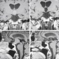
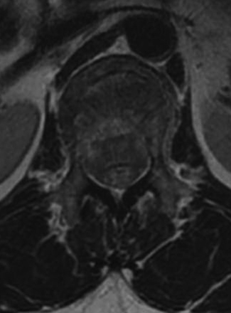
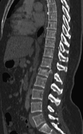
Detailed history and thorough physical and neurologic examination are mandatory. Concomitant injuries including intracranial visceral and spinal injuries at other levels are very common in the setting of high-energy vertebral fractures and must be fully assessed.9–11 Before designing a treatment plan, plain radiograph and computed tomography (CT) scans are performed (Figs. 178-1 and 178-2). MRI of the affected spine area is useful for evaluating soft tissue injury, including the intervertebral disc and the PLC, as well as for identifying epidural hematomas and spinal cord lesions (Figs. 178-3 and 178-4). The accuracy of MRI in identifying PLC injuries has been questioned,12,13 and refined diagnostic criteria are still required. Goals of surgical treatment are reduction of the fracture and reconstruction of the normal spinal architecture, stable fixation of the affected spinal segment, decompression of the spinal cord and prevention of new spinal cord injuries, early mobilization, and optimal medical and surgical treatment in polytraumatized patients.
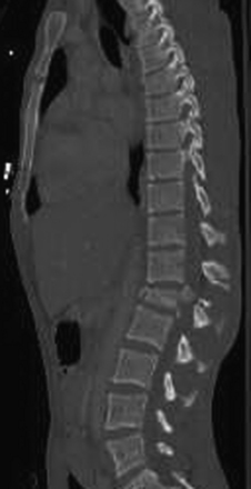
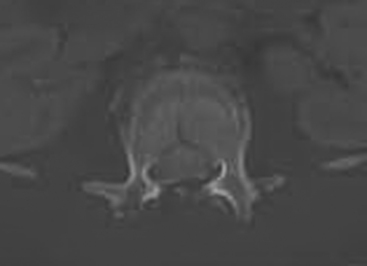
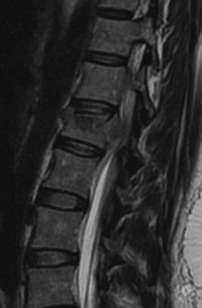
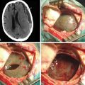
FIGURE 178-3 A 40-year-old woman presented with incomplete injury after a fall. Magnetic resonance imaging shows an L1 fracture.
The best timing for surgical treatment of thoracolumbar fractures is another hotly debated issue. Early stabilization of the spine is positively correlated with favorable long-term clinical outcome.14,15 Data from degenerative conditions and animal studies suggest that early decompression is beneficial in patients who suffer from spinal cord injury; nevertheless, clinical data regarding spinal cord injury accompanying vertebral fractures is not conclusive.14,16 Some protocols have been suggested to identify cases that will benefit the best from early decompression, but conclusive data do not yet exist.17 It is recommended that the spine be stabilized and decompressed as early as possible given the patient’s general condition, and not necessarily on an emergent basis. Options for surgical management of thoracolumbar fractures include anterior, posterior, or combined approaches.
Posterior Stabilization
The standard midline posterior approach is performed. Any damage to fascial and muscular layers as well as the supraspinous ligament should be noted at the time of exposure. Careful exposure of the posterior bony and ligamentous structures follows. In cases where laminar or spinous process fractures have been documented, the dura might be bulging through the fracture defect. The ligamentum flavum should be carefully exposed for the same reason. The dissection is then carried out laterally to expose the facet joint capsule and the transverse processes completely. The facet joint capsule should be left intact in levels that are not to be fused. Exposure of the injured level typically involves a fair amount of bleeding from injured muscles, fractured bone surfaces, or damaged epidural vessels. Hemostatic agents such as thrombin-soaked Gelfoam and bone wax should be readily available. If spinal cord decompression is required, transpedicular resection can offer a corridor to the ventral spinal canal. The pedicle can be removed with a high-speed drill, and instruments such as Woodson elevators and down-going curettes can be used to push bony fragments anteriorly away from the canal (Fig. 178-5).
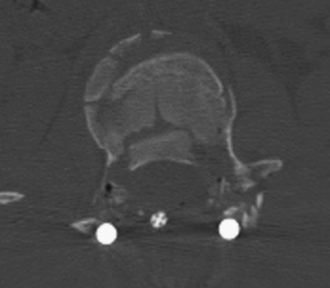
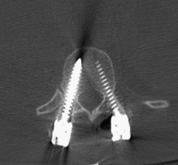
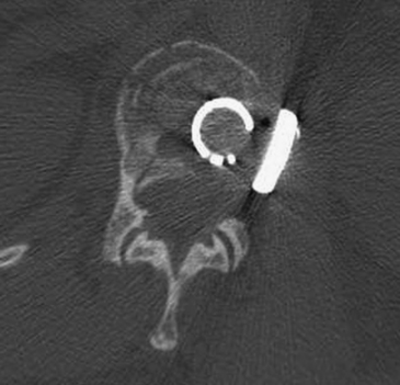
FIGURE 178-5 The patient underwent transpedicular decompression of L1. Canal diameter has been restored.
Throughout the years many instrumentation devices were developed for posterior spinal stabilization. Sublaminar wiring and sublaminar or transverse process hooks are valid instrumentation options and can be used both primarily and in cases where anatomic or pathologic parameters prevent the use of pedicle screws. Pedicle screws have superior biomechanical properties, including better pullout resistance and stabilization of all three spinal columns, as opposed to the posterior column alone with the other devices.18–20 This has driven most spine surgeons toward the use of pedicle screws despite the higher skill level required, and this is now considered standard technique for posterior instrumentation.21,22
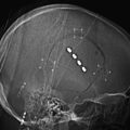
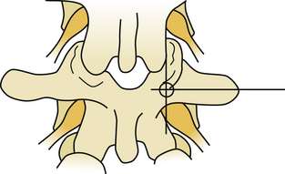
Several techniques have been described for finding the entry point for pedicle screws. A freehand technique uses the anatomic landmarks.23 In the lumbar spine, the entry point is found at the junction of the spinous process bisector and lateral border of the pars interarticularis (Fig 178-6). In the thoracic spine, the entry point varies with the level. As a general rule, in the mid-thoracic region, the entry points are relatively medial and cranial, at the junction of the proximal transverse process and just lateral to the middle of the superior facet location, though more lateral and caudal at the cranial and caudal levels24 (Fig. 178-7). X-ray or fluoroscopy can be used to identify the bull’s-eye sign that is formed by the cortical borders of the pedicle.25 This can be used to drive a guide wire or Steinman pin into the pedicle or to remove the posterior cortex. Imaging can be very challenging in the upper thoracic spine due to the thoracic kyphosis and rib angles, in obese patients, in patients with very poor bone quality, or in patients with spinal deformities. When an entry point cannot be verified, a laminotomy can be used to palpate the pedicle wall with a curved curette or a dental probe.
Once the entry point is identified, a sharp awl, Leksell rongeur, or high-speed drill is used to remove the posterior cortex. A blunt gearshift pedicle finder is then used to identify a trajectory through the pedicle’s cancellous bone and down to the posterior vertebral cortex. The posterior vertebral cortex is breached and the anterior vertebral cortex is palpated but not breached. A ball-tip probe is used to probe the trajectory walls and to verify intact bony wall at all four aspects of the canal and an intact anterior cortex. The probe or a depth gauge is used to determine screw length. Screw length varies from 25 mm for the upper thoracic and 60 mm for the lower lumbar.26 Tapping of the pilot hole is recommended, usually 0.5 to 1 mm undertapping.27 Probing of the borders can be repeated after tapping, because it is easier to feel gaps and breaches along the threaded bony walls.
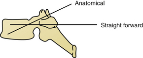
On the sagittal plane, the straightforward trajectory that is parallel to the upper endplate of the vertebral body was found biomechanically better than the anatomic trajectory that is perpendicular to the dorsal cortex and points down to the antero-inferior corner of the vertebral body.28 The axial angle might be more difficult to determine and ranges between 25 and 30 degrees of convergence in T1 to 0 to 4 degrees of divergence at T12. Screw diameter is also subject to great variation. Factors such as the patient’s age, sex, and body size influence overall screw diameter, and the spine level determines the specific screw size. Typically T6 and T7 have the smallest pedicles, and the lower lumbar levels have the largest.29 Screw diameters of 4.5 mm to 6 mm should be available. Because most patients undergo preoperative CT of the spine, it is highly recommended to plan the trajectories and estimate screw lengths and diameters before surgery.23
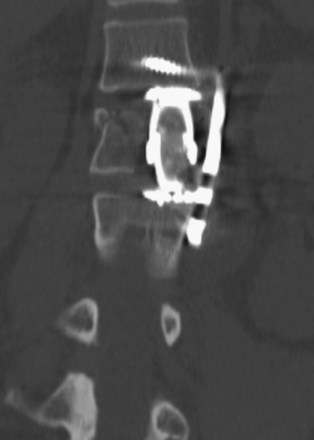
Once pedicle screw insertion is completed, x-rays are taken to verify screw trajectories at all levels. AP and lateral planes are used, although some surgeons perform lateral films only30 (Fig. 178-8). Fracture-related deformity is corrected through positioning, and residual deformity is reduced by prebent rod fixation and careful compression and distraction maneuvers.31 The connecting rod is contoured to approximate the normal spinal contour and locked to the screw heads. Crosslink devices have been shown to increase the rigidity of the construct.32 Anterior bone fragments that bulge into the canal are often reduced when the vertebral height is restored.33 Further reduction can be achieved via laminotomy when a curved curette or impactor is passed around the thecal sac and gentle tapping of the posterior vertebral cortex is possible.
Fixation devices have been recommended to include two spinal levels above the fracture level and one or two levels caudal to the fracture level.34,35 Such long segment spinal fixation fuses four or five spinal motion segments and therefore might result in significant loss of mobility and increased risk for adjacent level morbidity. In an attempt to lessen the latter, short segment instrumentation has been introduced, fusing only two motion segments. Mixed results with the use of short-segment instrumentation have been reported, with some good long- and short-term results36 and some failures.37,38 Better radiographic outcome does not fully correlate with clinical results.39 Transpedicular bone grafting does not seem to improve short segment instrumentation outcome,40,41 but insertion of pedicle screws in the fractured vertebra, when feasible, does.42,43 Augmentation of the vertebral body with bone cement might present a valid adjunct to the posterior instrumentation.44,45 We recommend short segment instrumentation be used in selected, mildly comminuted burst fractures only, and longer-segment instrumentation should be for all other fractures that are treated with the posterior approach only.46,47
Decortication of the lateral gutters and the transverse processes is essential to ensure maximal bony fusion. A power drill, osteotome, or a curette is used to expose bleeding cancellous bone and remove cartilage from the facet joint at the levels to be fused. The use of autologous iliac crest bone graft is constantly declining owing to donor site morbidity.48 Alternatives to iliac crest bone grafting include autologous bone from spinous processes and laminae, morselized allograft, or bone substitutes such as calcium phosphate or hydroxyapatite that can be mixed with a bone marrow aspirate or demineralized bone matrix.49
Decompressive laminectomy was not found to improve neurologic outcome of spinal cord injuries accompanying thoracolumbar fractures.1 It was, however, found to be related with higher rates of implant failure and is therefore not recommended.50 New technologies have been introduced to improve the accuracy of pedicle screws and the reproducibility of the insertion technique. Intraoperative three-dimensional imaging51 and computer-assisted navigation systems52 have been found to improve the trajectory accuracy of pedicle screws and to reduce the radiation exposure of the operating room personnel (Fig. 178-9). Intraoperative electromyography (EMG) can be used to detect breached or misplaced pedicle screws by monitoring muscle activity in the rectus abdominis or lower limbs.53 Intraoperative EMG can be time-consuming, and the actual benefits are yet to be proved.54
Meticulous multilayer wound closure is imperative in posterior instrumentation for thoracolumbar fractures. The soft tissue damage can lead to accumulation of hematomas and seromas, wound infections, skin necrosis, and wound dehiscence. Most patients who do not suffer associated debilitating injuries are able to mobilize on the first postoperative day. We are not familiar with any study directly addressing the use of postoperative bracing, but a thoracolumbar sacral orthosis (TLSO) is usually recommended for a period of 4 weeks to 3 months after surgery depending on fracture type, instrumentation length, bone quality, and activity level (Fig. 178-10).
Anterolateral Approach
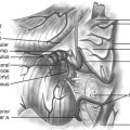
Transpleural thoracotomy can be used for the treatment of fractures from T3 to L1; for the thoracolumbar region (T11–L1), the diaphragm should be divided and the retroperitoneal space entered. Purely lumbar fractures are approached through an anterior retroperitoneal approach.55 A patient undergoing a thoracotomy must be hemodynamically stable enough to withstand a single lung intubation and possible significant blood loss. For cases where release of the ventral dura and anterior reconstruction is required, but single lung ventilation is not feasible, the costotransversectomy or lateral extracavitary approaches can be used.56 Although many spine surgeons perform the thoracotomy themselves, others choose to have thoracic, general, or vascular surgeons complete the surgical approach, mobilize the vessels to expose the bony elements, and assist with pleura and wound closure and placement of drains. In addition to other imaging studies as previously discussed, a plain AP x-ray or CT scout view is obtained to confirm the number of ribs. Having a cell-saver system readily available for the procedure is often useful (Fig. 178-11).
The aorta and the segmental arteries are now exposed and the segmental artery of the level to be resected is ligated and divided. Although significant neurologic injury is a rare consequence of single-sided segmental artery ligation, incidents of spinal cord ischemia have been reported.57 The number of segmental arteries ligated was found to be correlated with the risk for cord ischemia and therefore should be kept to the necessary minimum.58 Rib heads of the involved levels can be removed to achieve better visualization of the intervertebral discs above and beyond the affected vertebral body, as well as the neural foramina. Recognition of neural foramina borders is the key to determining the location of the anterior border of the spinal canal and the dorsal margin of safe corpectomy. The superior and inferior borders of the pedicles are palpated with a nerve hook or a Penfield dissector. The pedicle is then removed using Kerrison rongeurs. The dura mater is now visible and the dorsal border of the vertebral body can be carefully palpated.
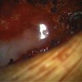
Excision of the intervertebral disc both cranial and caudal to the affected vertebral body defines the corpectomy borders. Leksell rongeurs are used to complete the corpectomy and the bone is preserved for bone grafting. When a sufficient amount of the bone is removed, a power drill and Kerrison rongeurs are used to remove the remaining bone, disc, and posterior longitudinal ligament material from the dorsal aspect of the cavity. The thecal sac should be free from any compressing fragment (Fig. 178-12). Epidural bleeding can become significant at this stage, and hemostatic agents should be readily available. Ventral and contralateral vertebral body cortices may be left intact because they will not compromise graft placement, vertebral height restoration, or spinal canal decompression. Superior and inferior endplates are scraped clean of any cartilage using straight and curved curettes, and they are decorticated to bleeding bone. The release is bounded by the superior and inferior adjacent vertebral endplates and the contralateral pedicle.
Reconstruction of the intervertebral space was traditionally accomplished using a tricortical iliac crest autograft. As with posterior bone grafting, the iliac crest autograft is being increasingly replaced by allografts and cages made from metallic or compound materials.59,60 All nonautologous implants should be packed with the corpectomy bone for its osteoinductive properties, and struts from the resected rib can be placed around the implant (Fig. 178-13). The corpectomy gap is measured with a compass or a micrometer and a cage of the proper size is selected or cut to size. The largest implant diameter should be chosen, ensuring it does not protrude out of the endplates. Vertebral height can be restored by gently applying anterior force on the spine from the posterior aspect or by using a spreader. The implant is gently tapped into the defect and fluoroscopy is used to verify its position as well as the spinal curvature.
Expandable cages are gaining popularity because they do not necessitate accurate measurement of the vertebral body void or intraoperative cutting of a mesh cage, and they can actually be used to restore the collapsed vertebral height by expanding the cage in the intervertebral space. The disadvantages of expandable cages include their higher price, slightly higher technical complexity, and limited inner diameter for autograft.61
Mechanical properties of standalone thoracolumbar cages have been found to be unsatisfactory, and supplementary instrumentation is recommended. Instrumentation devices include screw-and-rod constructs or compression plates (Fig. 178-14). With screw-and-rod constructs, screws are inserted into the vertebral body, obtaining bicortical purchase. The contralateral cortex can be palpated by the surgeon to verify that the screw head is not protruding or damaging the adjacent structures. Many systems use washers to increase screw head contact surface and prevent subsidence into the thin vertebral cortex, and some include washers on the contralateral side as well. The screws should be inserted perpendicular to the endplate on the coronal plane. The posterior screw is angled 10 degrees anteriorly to avoid the spinal canal. The anterior screw can be perpendicular or angled 10 degrees posteriorly to improve pullout strength. Screw trajectory and size is verified using fluoroscopy. If a rod system is used, the anterior rod is placed first and, if not already performed, the vertebral body height can be restored by distraction along the rod. The implant can then be easily inserted into the gap and bone graft placed around it. The posterior rod is then placed and compression is applied to both rods. The cap screws are locked and a cross-connector is used to improve implant stability and rigidity. Fluoroscopy is used again to verify definite placement of all implant components, and the wound is closed in layers. A chest drain is placed under water-seal suction and is removed when it is draining less than 100 ml in 24 hours. The patient is mobilized as soon as possible depending on the general and respiratory condition.
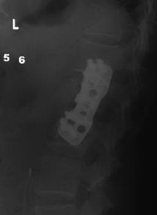
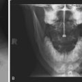
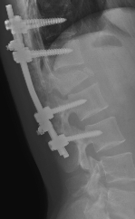
FIGURE 178-14 Lateral x-ray shows nice placement of the plate. The patient made a good recovery and became neurologically normal.
The high morbidity associated with the open anterolateral approach to the thoracic spine inspired the development of mini-open and thoracoscopic approaches for the treatment of spine fractures. The development of expandable cages and specifically designed hardware have made this minimally invasive procedure even more appealing. Reports of adequate canal clearance and restoration of vertebral height with reduced perioperative morbidity should be weighed against the steep learning curve of the endoscopic technique.62,63
Discussion
The posterior approach to the thoracolumbar spine is the most commonly used approach for the treatment of a variety of degenerative, traumatic, and neoplastic pathologies. Most spine surgeons are comfortable with lumbar and thoracic pedicle screw insertion techniques. The posterior approach enables correction of kyphotic deformity and stabilization of all three spinal columns when using pedicle screws.64 Decompression of the thecal sac is achieved indirectly by positioning and distraction. Impaction of anterior bony fragments with a curved instrument can be used to further decompress the spinal canal. Short-segment posterior fixation of complex thoracolumbar fractures have yielded inconsistent results. Longer segment fusion may be required, resulting in a higher degree of spinal movement limitation and adjacent segment loading.
Biomechanical in vitro studies have shown mixed results when comparing the stability of anterior, posterior, and combined constructs.65–67 When comparing results of patients treated with an anterior approach versus posterior approach, no significant differences were found in neurologic improvement and functional results, and results were inconclusive regarding maintenance of kyphosis correction.4,16,68–70 Despite good reported results for anterior instrumentation alone even in the treatment of three-column injury,71–73 many surgeons consider it insufficient for spine stabilization in the presence of posterior ligamentous injury; when anterior decompression is warranted, a combined anterior and posterior instrumentation may be performed.74
When severe anterior column injury is present, a posterolateral approach may be used for anterior column reconstruction. Costotransversectomy, transpedicular decompression, and the lateral extracavitary approach have all been shown to have good outcome in decompressing the ventral aspect of the thecal sac and reconstructing the anterior column. These approaches have become more feasible with the development of expandable cages.75–77
We recommend posterior reduction and instrumentation for most uncomplicated thoracolumbar fractures and when injury to the posterior ligamentous complex is apparent because of this procedure’s relative simplicity and better complication profile with at least comparable results. In cases where incomplete or worsening neurologic injury is diagnosed in the presence of severe canal compromise, anterior decompression may be considered, with or without posterior pedicle screw instrumentation and fusion as a single or staged procedure. Patient factors such as osteoporosis or concomitant injuries should also be considered when deciding whether to perform an anterior, posterior, or combined procedure.71
Acknowledgment
The authors are grateful to Karen K. Anderson, B.S., for her assistance with manuscript preparation.
Andress H., Braun H., Helmberger T., et al. Long-term results after posterior fixation of thoraco-lumbar burst fractures. Injury. 2002;33(4):357-365.
Banwart J.C., Asher M.A., Hassanein R.S. Iliac crest bone graft harvest donor site morbidity. A statistical evaluation. Spine. 1995;20(9):1055-1060.
Boden S.D. Overview of the biology of lumbar spine fusion and principles for selecting a bone graft substitute. Spine. 2002;27(16 Suppl 1):S26-S31.
Cengiz S.L., Kalkan E., Bayir A., et al. Timing of thoracolumbar spine stabilization in trauma patients; impact on neurological outcome and clinical course. A real prospective randomized controlled study. Arch Orthop Trauma Surg. 2008;128(9):959-966.
Dai L., Jiang L., Jiang S. Anterior-only stabilization using plating with bone structural autograft versus titanium mesh cages for two- or three-column thoracolumbar burst fractures: a prospective randomized study. Spine. 2009;34(14):1429-1435.
Dai L., Jiang L., Jiang S. Conservative treatment of thoracolumbar burst fractures: long-term follow-up results with special reference to the load sharing classification. Spine. 2008;33(23):2536-2544.
Garfin S.R., Mowery C.A., Guerra J., et al. Confirmation of the posterolateral technique to decompress and fuse thoracolumbar spine burst fractures. Spine. 1985;10(3):218-223.
Gertzbein S.D. Scoliosis Research Society. Multicenter spine fracture study. Spine. 1992;17(5):528-540.
Hartl R., Theodore N., Dickman C., et al. Anterior approaches for the management of thoracic spine fractures. Oper Tech Neurosurg. 2004;7(1):31-41.
Iida Y., Kataoka O., Sho T., et al. Postoperative lumbar spinal instability occurring or progressing secondary to laminectomy. Spine. 1990;15(11):1186-1189.
Kim Y.J., Lenke L.G., Bridwell K.H., et al. Free hand pedicle screw placement in the thoracic spine: is it safe? Spine. 2004;29(3):333-342.
Korovessis P., Baikousis A., Koureas G., et al. Correlative analysis of the results of surgical treatment of thoracolumbar injuries with long Texas Scottish Rite Hospital construct: is the use of pedicle screws versus hooks advantageous in the lumbar spine? J Spinal Disord Tech. 2004;17(3):195-205.
Korovessis P., Repantis T., Petsinis G., et al. Direct reduction of thoracolumbar burst fractures by means of balloon kyphoplasty with calcium phosphate and stabilization with pedicle-screw instrumentation and fusion. Spine. 2008;33(4):E100-E108.
Mahar A., Kim C., Wedemeyer M., et al. Short-segment fixation of lumbar burst fractures using pedicle fixation at the level of the fracture. Spine. 2007;32(14):1503-1507.
McLain R.F., Sparling E., Benson D.R. Early failure of short-segment pedicle instrumentation for thoracolumbar fractures. A preliminary report. J Bone Joint Surg Am. 1993;75(2):162-167.
Patel A.A., Dailey A., Brodke D.S., et al. Thoracolumbar spine trauma classification: the Thoracolumbar Injury Classification and Severity Score system and case examples. J Neurosurg Spine. 2009;10(3):201-206.
Robertson P.A., Stewart N.R. The radiologic anatomy of the lumbar and lumbosacral pedicles. Spine. 2000;25(6):709-715.
Rutges J.P., Oner F.C., Leenen L.P. Timing of thoracic and lumbar fracture fixation in spinal injuries: a systematic review of neurological and clinical outcome. Eur Spine J. 2007;16(5):579-587.
Sasso R.C., Best N.M., Reilly T.M., et al. Anterior-only stabilization of three-column thoracolumbar injuries. J Spinal Disord Tech. 2005;18(Suppl):S7-S14.
Snell B.E., Nasr F.F., Wolfla C.E. Single-stage thoracolumbar vertebrectomy with circumferential reconstruction and arthrodesis: surgical technique and results in 15 patients. Neurosurgery. 2006;58(4 Suppl 2):263-268. ONS-
Vaccaro A.R., Rihn J.A., Saravanja D., et al. Injury of the posterior ligamentous complex of the thoracolumbar spine: a prospective evaluation of the diagnostic accuracy of magnetic resonance imaging. Spine. 2009;34(23):E841-E847.
Verlaan J.J., Diekerhof C.H., Buskens E., et al. Surgical treatment of traumatic fractures of the thoracic and lumbar spine: a systematic review of the literature on techniques, complications, and outcome. Spine. 2004;29(7):803-814.
Wood K.B., Bohn D., Mehbod A. Anterior versus posterior treatment of stable thoracolumbar burst fractures without neurologic deficit: a prospective, randomized study. J Spinal Disord Tech. 2005;18(Suppl):S15-S23.
Yi L., Jingping B., Gele J., et al. Operative versus non-operative treatment for thoracolumbar burst fractures without neurological deficit. Cochrane Database Syst Rev, 2006;4:CD005079
Zdeblick T.A., Sasso R.C., Vaccaro A.R., et al. Surgical treatment of thoracolumbar fractures. Instr Course Lect. 2009;58:639-644.
1. Gertzbein S.D. Scoliosis Research Society. Multicenter spine fracture study. Spine. 1992;17(5):528-540.
2. Magerl F., Aebi M., Gertzbein S.D., et al. A comprehensive classification of thoracic and lumbar injuries. Eur Spine J. 1994;3(4):184-201.
3. Hu R., Mustard C.A., Burns C. Epidemiology of incident spinal fracture in a complete population. Spine. 1996;21(4):492-499.
4. Verlaan J.J., Diekerhof C.H., Buskens E., et al. Surgical treatment of traumatic fractures of the thoracic and lumbar spine: a systematic review of the literature on techniques, complications, and outcome. Spine. 2004;29(7):803-814.
5. Dai L., Jiang L., Jiang S. Conservative treatment of thoracolumbar burst fractures: long-term follow-up results with special reference to the load sharing classification. Spine. 2008;33(23):2536-2544.
6. Yi L., Jingping B., Gele J., et al. Operative versus non-operative treatment for thoracolumbar burst fractures without neurological deficit. Cochrane Database Syst Rev, 2006;4:CD005079
7. Thomas K.C., Bailey C.S., Dvorak M.F., et al. Comparison of operative and nonoperative treatment for thoracolumbar burst fractures in patients without neurological deficit: a systematic review. J Neurosurg Spine. 2006;4(5):351-358.
8. Patel A.A., Dailey A., Brodke D.S., et al. Thoracolumbar spine trauma classification: the Thoracolumbar Injury Classification and Severity Score system and case examples. J Neurosurg Spine. 2009;10(3):201-206.
9. Rabinovici R., Ovadia P., Mathiak G., et al. Abdominal injuries associated with lumbar spine fractures in blunt trauma. Injury. 1999;30(7):471-474.
10. Chu D., Lee Y., Lin C., et al. Prevalence of associated injuries of spinal trauma and their effect on medical utilization among hospitalized adult subjects—a nationwide data-based study. BMC Health Serv Res. 2009;9(1):137.
11. Saboe L.A., Reid D.C., Davis L.A., et al. Spine trauma and associated injuries. J Trauma. 1991;31(1):43-48.
12. Vaccaro A.R., Rihn J.A., Saravanja D., et al. Injury of the posterior ligamentous complex of the thoracolumbar spine: a prospective evaluation of the diagnostic accuracy of magnetic resonance imaging. Spine. 2009;34(23):E841-E847.
13. Dai L., Ding W., Wang X., et al. Assessment of ligamentous injury in patients with thoracolumbar burst fractures using MRI. J Trauma. 2009;66(6):1610-1615.
14. Rutges J.P., Oner F.C., Leenen L.P. Timing of thoracic and lumbar fracture fixation in spinal injuries: a systematic review of neurological and clinical outcome. Eur Spine J. 2007;16(5):579-587.
15. Cengiz S.L., Kalkan E., Bayir A., et al. Timing of thoracolumbar spine stabilization in trauma patients; impact on neurological outcome and clinical course. A real prospective randomized controlled study. Arch Orthop Trauma Surg. 2008;128(9):959-966.
16. Kingwell S.P., Curt A., Dvorak M.F. Factors affecting neurological outcome in traumatic conus medullaris and cauda equina injuries. Neurosurg Focus. 2008;25(5):E7.
17. Mouchaty H., Conti P., Conti R., et al. Assessment of three year experience of a strategy for patient selection and timing of operation in the management of acute thoracic and lumbar spine fractures: a prospective study. Acta Neurochir (Wien). 2006;148(11):1181-1187.
18. Liljenqvist U., Hackenberg L., Link T., et al. Pullout strength of pedicle screws versus pedicle and laminar hooks in the thoracic spine. Acta Orthop Belg. 2001;67(2):157-163.
19. Hitchon P.W., Brenton M.D., Black A.G., et al. In vitro biomechanical comparison of pedicle screws, sublaminar hooks, and sublaminar cables. J Neurosurg. 2003;99(Suppl 1):104-109.
20. Korovessis P., Baikousis A., Koureas G., et al. Correlative analysis of the results of surgical treatment of thoracolumbar injuries with long Texas Scottish Rite Hospital construct: is the use of pedicle screws versus hooks advantageous in the lumbar spine? J Spinal Disord Tech. 2004;17(3):195-205.
21. Hartl R., Theodore N., Dickman C., et al. Anterior approaches for the management of thoracic spine fractures. Oper Tech Neurosurg. 2004;7(1):31-41.
22. Hartl R., Theodore N., Dickman C., et al. Technique of thoracic pedicle screw fixation for trauma. Oper Tech Neurosurg. 2004;7(1):22-30.
23. Karapinar L., Erel N., Ozturk H., et al. Pedicle screw placement with a free hand technique in thoracolumbar spine: is it safe? J Spinal Disord Tech. 2008;21(1):63-67.
24. Kim Y.J., Lenke L.G., Bridwell K.H., et al. Free hand pedicle screw placement in the thoracic spine: is it safe? Spine. 2004;29(3):333-342.
25. Robertson P.A., Stewart N.R. The radiologic anatomy of the lumbar and lumbosacral pedicles. Spine. 2000;25(6):709-715.
26. Berry J.L., Moran J.M., Berg W.S., et al. A morphometric study of human lumbar and selected thoracic vertebrae. Spine. 1987;12(4):362-367.
27. Kuklo T.R., Lehman R.A. Effect of various tapping diameters on insertion of thoracic pedicle screws: a biomechanical analysis. Spine. 2003;28(18):2066-2071.
28. Lehman R.A., Polly D.W., Kuklo T.R., et al. Straight-forward versus anatomic trajectory technique of thoracic pedicle screw fixation: a biomechanical analysis. Spine. 2003;28(18):2058-2065.
29. Zindrick M.R., Wiltse L.L., Doornik A., et al. Analysis of the morphometric characteristics of the thoracic and lumbar pedicles. Spine. 1987;12(2):160-166.
30. Odgers C.J.4th, Vaccaro A.R., Pollack M.E., et al. Accuracy of pedicle screw placement with the assistance of lateral plain radiography. J Spinal Disord. 1996;9(4):334-338.
31. Silvestro C., Francaviglia N., Bragazzi R., et al. Near-anatomical reduction and stabilization of burst fractures of the lower thoracic or lumbar spine. Acta Neurochir (Wien). 1992;116(1):53-59.
32. Lynn G., Mukherjee D.P., Kruse R.N., et al. Mechanical stability of thoracolumbar pedicle screw fixation. The effect of crosslinks. Spine. 1997;22(14):1568-1572.
33. Crutcher J.P., Anderson P.A., King H.A., et al. Indirect spinal canal decompression in patients with thoracolumbar burst fractures treated by posterior distraction rods. J Spinal Disord. 1991;4(1):39-48.
34. Zdeblick T.A., Sasso R.C., Vaccaro A.R., et al. Surgical treatment of thoracolumbar fractures. Instr Course Lect. 2009;58:639-644.
35. Modi H.N., Chung K.J., Seo I.W., et al. Two levels above and one level below pedicle screw fixation for the treatment of unstable thoracolumbar fracture with partial or intact neurology. J Orthop Surg Res. 2009;4:28.
36. McNamara M.J., Stephens G.C., Spengler D.M. Transpedicular short-segment fusions for treatment of lumbar burst fractures. J Spinal Disord. 1992;5(2):183-187.
37. McLain R.F., Sparling E., Benson D.R. Early failure of short-segment pedicle instrumentation for thoracolumbar fractures. A preliminary report. J Bone Joint Surg Am. 1993;75(2):162-167.
38. Korovessis P., Baikousis A., Zacharatos S., et al. Combined anterior plus posterior stabilization versus posterior short-segment instrumentation and fusion for mid-lumbar (L2–L4) burst fractures. Spine. 2006;31(8):859-868.
39. Tezeren G., Kuru I. Posterior fixation of thoracolumbar burst fracture: short-segment pedicle fixation versus long-segment instrumentation. J Spinal Disord Tech. 2005;18(6):485-488.
40. Andress H., Braun H., Helmberger T., et al. Long-term results after posterior fixation of thoraco-lumbar burst fractures. Injury. 2002;33(4):357-365.
41. Knop C., Fabian H.F., Bastian L., et al. Late results of thoracolumbar fractures after posterior instrumentation and transpedicular bone grafting. Spine. 2001;26(1):88-99.
42. Mahar A., Kim C., Wedemeyer M., et al. Short-segment fixation of lumbar burst fractures using pedicle fixation at the level of the fracture. Spine. 2007;32(14):1503-1507.
43. Guven O., Kocaoglu B., Bezer M., et al. The use of screw at the fracture level in the treatment of thoracolumbar burst fractures. J Spinal Disord Tech. 2009;22(6):417-421.
44. Marco R.A.W., Kushwaha V.P. Thoracolumbar burst fractures treated with posterior decompression and pedicle screw instrumentation supplemented with balloon-assisted vertebroplasty and calcium phosphate reconstruction. J Bone Joint Surg Am. 2009;91(1):20-28.
45. Korovessis P., Repantis T., Petsinis G., et al. Direct reduction of thoracolumbar burst fractures by means of balloon kyphoplasty with calcium phosphate and stabilization with pedicle-screw instrumentation and fusion. Spine. 2008;33(4):E100-E108.
46. Altay M., Ozkurt B., Aktekin C.N., et al. Treatment of unstable thoracolumbar junction burst fractures with short- or long-segment posterior fixation in magerl type a fractures. Eur Spine J. 2007;16(8):1145-1155.
47. Parker J.W., Lane J.R., Karaikovic E.E., et al. Successful short-segment instrumentation and fusion for thoracolumbar spine fractures: a consecutive 4½ year series. Spine. 2000;25(9):1157-1170.
48. Banwart J.C., Asher M.A., Hassanein R.S. Iliac crest bone graft harvest donor site morbidity. A statistical evaluation. Spine. 1995;20(9):1055-1060.
49. Boden S.D. Overview of the biology of lumbar spine fusion and principles for selecting a bone graft substitute. Spine. 2002;27(16 Suppl 1):S26-S31.
50. Iida Y., Kataoka O., Sho T., et al. Postoperative lumbar spinal instability occurring or progressing secondary to laminectomy. Spine. 1990;15(11):1186-1189.
51. Nottmeier E.W., Seemer W., Young P.M. Placement of thoracolumbar pedicle screws using three-dimensional image guidance: experience in a large patient cohort. J Neurosurg Spine. 2009;10(1):33-39.
52. Amiot L.P., Lang K., Putzier M., et al. Comparative results between conventional and computer-assisted pedicle screw installation in the thoracic, lumbar, and sacral spine. Spine. 2000;25(5):606-614.
53. Calancie B., Madsen P., Lebwohl N. Stimulus-evoked EMG monitoring during transpedicular lumbosacral spine instrumentation. Initial clinical results. Spine. 1994;19(24):2780-2786.
54. Reidy D.P., Houlden D., Nolan P.C., et al. Evaluation of electromyographic monitoring during insertion of thoracic pedicle screws. J Bone Joint Surg Br. 2001;83(7):1009-1014.
55. McAfee P.C., Bohlman H.H., Yuan H.A. Anterior decompression of traumatic thoracolumbar fractures with incomplete neurological deficit using a retroperitoneal approach. J Bone Joint Surg Am. 1985;67(1):89-104.
56. Garfin S.R., Mowery C.A., Guerra J., et al. Confirmation of the posterolateral technique to decompress and fuse thoracolumbar spine burst fractures. Spine. 1985;10(3):218-223.
57. Ikard R.W. Methods and complications of anterior exposure of the thoracic and lumbar spine. Arch Surg. 2006;141(10):1025-1034.
58. Yuan L., Ni G.X., Luk K.K., et al. Effect of segmental artery ligation on the blood supply of the thoracic spinal cord during anterior spinal surgery: a quantitative histomorphological fresh cadaver study. Spine. 2005;30(5):483-486.
59. Dvorak M.F., Kwon B.K., Fisher C.G., et al. Effectiveness of titanium mesh cylindrical cages in anterior column reconstruction after thoracic and lumbar vertebral body resection. Spine. 2003;28(9):902-908.
60. Vaccaro A.R., Cirello J. The use of allograft bone and cages in fractures of the cervical, thoracic, and lumbar spine. Clin Orthop Relat Res. 2002;394:19-26.
61. Shen F.H., Marks I., Shaffrey C., et al. The use of an expandable cage for corpectomy reconstruction of vertebral body tumors through a posterior extracavitary approach: a multicenter consecutive case series of prospectively followed patients. Spine J. 2008;8(2):329-339.
62. Beisse R., Mückley T., Schmidt M.H., et al. Surgical technique and results of endoscopic anterior spinal canal decompression. J Neurosurg Spine. 2005;2(2):128-136.
63. Khoo L.T., Beisse R., Potulski M. Thoracoscopic-assisted treatment of thoracic and lumbar fractures: a series of 371 consecutive cases. Neurosurgery. 2002;51(suppl 5):S104-S117.
64. Ramieri A., Domenicucci M., Cellocco P., et al. Effectiveness of posterior tension band fixation in the thoracolumbar seat-belt type injuries of the young population. Eur Spine J. 2009;18(Suppl 1):89-94.
65. Shono Y., McAfee P.C., Cunningham B.W. Experimental study of thoracolumbar burst fractures. A radiographic and biomechanical analysis of anterior and posterior instrumentation systems. Spine. 1994;19(15):1711-1722.
66. Acosta F.L.Jr., Buckley J.M., Xu Z., et al. Biomechanical comparison of three fixation techniques for unstable thoracolumbar burst fractures. Laboratory investigation. J Neurosurg Spine. 2008;8(4):341-346.
67. Bence T., Schreiber U., Grupp T., et al. Two column lesions in the thoracolumbar junction: anterior, posterior or combined approach? A comparative biomechanical in vitro investigation. Eur Spine J. 2007;16(6):813-820.
68. Hitchon P.W., Torner J., Eichholz K.M., et al. Comparison of anterolateral and posterior approaches in the management of thoracolumbar burst fractures. J Neurosurg Spine. 2006;5(2):117-125.
69. Wood K.B., Bohn D., Mehbod A. Anterior versus posterior treatment of stable thoracolumbar burst fractures without neurologic deficit: a prospective, randomized study. J Spinal Disord Tech. 2005;18(Suppl):S15-S23.
70. Stancić M.F., Gregorović E., Nozica E., et al. Anterior decompression and fixation versus posterior reposition and semirigid fixation in the treatment of unstable burst thoracolumbar fracture: prospective clinical trial. Croat Med J. 2001;42(1):49-53.
71. Mariotti A.J., Diwan A.D. Current concepts in anterior surgery for thoracolumbar trauma. Orthop Clin North Am. 2002;33(2):403-412. vii
72. Sasso R.C., Best N.M., Reilly T.M., et al. Anterior-only stabilization of three-column thoracolumbar injuries. J Spinal Disord Tech. 2005;18(Suppl):S7-S14.
73. Dai L., Jiang L., Jiang S. Anterior-only stabilization using plating with bone structural autograft versus titanium mesh cages for two- or three-column thoracolumbar burst fractures: a prospective randomized study. Spine. 2009;34(14):1429-1435.
74. Pflugmacher R., Schleicher P., Schaefer J., et al. Biomechanical comparison of expandable cages for vertebral body replacement in the thoracolumbar spine. Spine. 2004;29(13):1413-1419.
75. Kaya R.A., Aydin Y. Modified transpedicular approach for the surgical treatment of severe thoracolumbar or lumbar burst fractures. Spine J. 2004;4(2):208-217.
76. Snell B.E., Nasr F.F., Wolfla C.E. Single-stage thoracolumbar vertebrectomy with circumferential reconstruction and arthrodesis: surgical technique and results in 15 patients. Neurosurgery. 2006;58(4 Suppl 2):263-268. ONS-
77. Sasani M., Ozer A.F. Single-stage posterior corpectomy and expandable cage placement for treatment of thoracic or lumbar burst fractures. Spine. 2009;34(1):E33-E40.