[level-membership-for-critical-care-medicine-category]
CHAPTER 20 THE ROLE OF FOCUSED ASSESSMENT WITH SONOGRAPHY FOR TRAUMA: INDICATIONS, LIMITATIONS, AND CONTROVERSIES
Focused Assessment with Sonography for Trauma (FAST) has rapidly taken root in modern trauma care. FAST is an integral part of trauma algorithms, and is an important adjunct to the Advanced Trauma Life Support (ATLS) primary and secondary surveys. In 1997, the American Board of Surgery required the addition of ultrasonography into Accreditation Council for Graduate Medical Education (ACGME)–approved surgical training programs. The American College of Surgeons (ACS) has also incorporated FAST into the ATLS course and has sponsored multiple ultrasound training seminars.
FORMATION OF AN ULTRASOUND IMAGE
Proper visualization and accurate interpretation of an ultrasound image requires a basic understanding of ultrasound components, principles, physics, and terminology. The basic components of an ultrasound machine are listed in Table 1 and include the transmitter to send electrical signals to the transducer, the transducer to interconvert electrical energy and acoustic energy using the piezoelectric effect, the receiver to convert electrical signals into an image, and the monitor to display the image. An optional printer provides a hardcopy image.
| Component | Description |
|---|---|
| Transmitter | Sends electrical signals to transducer |
| Transducer | Interconverts electrical energy and acoustic energy by piezoelectric effect |
| Receiver | Converts electrical signals into image |
| Monitor | Displays image |
| Printer | Records hard copy of image (optional) |
There are three essential principles of ultrasonography (Table 2): the piezoelectric effect, pulse-echo principle, and acoustic impedance. Within the transducer, piezoelectric crystals expand and contract to interconvert electrical and mechanical energy, a process known as the piezoelectric effect. When an ultrasound wave contacts tissue, some of the signal is reflected and some is transmitted into tissue. The reflected waves bounce back and contact the crystals within the transducer, generating electrical impulses comparable to the strength of the returning wave. This is known as the pulse–echo principle. Acoustic impedance is the density of tissue multiplied by the speed of sound in tissue. The strength of the returning echo depends on the difference in density between the two structures imaged. Structures of different acoustic impedance (e.g., bile and gallstones) are relatively easy to distinguish from one another, whereas those of similar acoustic impedance (e.g., spleen and kidney) are more difficult to distinguish.1
Table 2 Essential Principles of Ultrasound
| Principle | Explanation |
|---|---|
| Piezoelectric effect | Piezoelectric crystals expand and contract to interconvert electrical and mechanical energy. |
| Pulse-echo principle | When an ultrasound wave contacts tissue, some of the signal is reflected and some is transmitted into tissue. These waves are then reflected to crystals within the transducer, generating electrical impulse comparable to the strength of the returning wave. |
| Acoustic impedance | Acoustic impedance is the density of tissue X speed of sound in tissue. The strength of the returning echo depends on the difference in density between the two structures imaged: structures of different acoustic impedance (e.g., bile and gallstones) are relatively easy to distinguish from one another, whereas those of similar acoustic impedance (e.g., spleen and kidney) are more difficult to distinguish. |
The basic physics of ultrasonography are important for good image formation, and terminology used for ultrasonography is listed in Table 3. Ultrasound waves are high-frequency (>20 kHz) mechanical radiant energy transmitted through a medium. The frequency (number of cycles/second) of medical diagnostic ultrasound is 2.5–10 MHz. As frequency increases, resolution improves, but penetration to deeper tissue decreases. Generally, the highest frequency transducer that produces the best resolution of the target organ is chosen (3.5 MHz for FAST). Common clinical applications of different ultrasound frequencies are listed in Table 4.
Table 3 Ultrasound Terminology
| Term | Definition |
|---|---|
| Ultrasound | High-frequency (>20 kHz) mechanical radiant energy transmitted through a medium |
| Frequency | Number of cycles per second (medical diagnostic ultrasound: 2.5–10 MHz) |
| Propagation speed | Speed at which wave travels through soft tissue (1540 m/sec) |
| Amplitude | Strength or height of wave |
| Attenuation | Decrease in amplitude and intensity of wave as it travels through medium |
| Absorption | Conversion of sound waves into heat |
| Scattering | Redirection of wave as it strikes rough or small boundary |
| Reflection | Return of wave toward transducer |
| Artifact | Error in imaging |
| Gain | Amplitude of returning waves based on tissue depth |
Table 4 Clinical Applications of Selected Transducer Frequencies
| Frequency | Application |
|---|---|
| 2.5–3.5 MHz | General abdominal |
| 5 MHz | Transvaginal, pediatric abdominal, testicular |
| 7.5 MHz | Vascular, soft tissue, thyroid |
The echogenicity of a structure is defined as the degree to which tissue echoes ultrasonic waves (generally reflected in ultrasound images as the degree of brightness). Tissues that reflect waves strongly will appear bright and are hyperechoic. Tissues that conduct ultrasound waves well are hypoechoic and are darker, while anechoic tissues conduct waves very well and appear black because essentially no waves are reflected back to the transducer. Isoechoic tissue transmits ultrasound similar to that of surrounding tissues, and is displayed with similar intensity (Table 5).1
Table 5 Terminology Used in Interpretation of Ultrasound Images
| Term | Definition |
|---|---|
| Echogenicity | Degree to which tissue echoes ultrasonic waves (generally reflected in ultrasound image as degree of brightness) |
| Anechoic | No internal echoes, appearing dark or black |
| Isoechoic | Having appearance similar to that of surrounding tissue |
| Hypoechoic | Less echoic (darker) than surrounding tissue |
| Hyperechoic | More echoic (brighter) than surrounding tissue |
TECHNIQUE
The patient’s identifying information is first entered to annotate the hardcopy ultrasound images. With the patient in the supine position, a liberal amount of ultrasound transmission gel is applied to the subxiphoid, left and right upper quadrants, and suprapubic areas. Using four transducer positions as shown in Figure 1, the pericardium and five dependent abdominal regions are examined for free fluid:


Although Morrison’s pouch was shown by Rozycki and colleagues2 to be the most sensitive for free intra-abdominal fluid, all five regions of the abdomen should be examined to maximize sensitivity of the test. Each area should be evaluated in two planes (longitudinal and transverse) with confirmation of positive regions using two views.
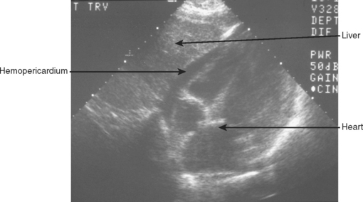
A 3.5-MHz convex transducer is oriented for sagittal sections and positioned in the subxiphoid area directing the transducer superiorly. Often, mild pressure on the transducer below the xiphoid toward the pericardial sac is required to visualize the heart. If this is unsuccessful, a left, parasternal, 4th or 5th intercostal view will be required. Obesity, rib/sternal fracture, subcutaneous emphysema, and a narrow subcostal angle may necessitate the parasternal view, and/or make this part of the examination indeterminate. Hemopericardium is detected by an anechoic band between the heart and the pericardial/diaphragmatic interface, as seen in Figure 2.
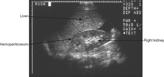
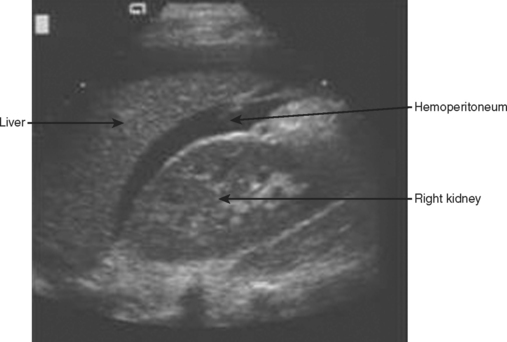
The right upper quadrant is then visualized by placing the transducer in the right mid to posterior axillary line, 11th intercostal space, in both longitudinal and transverse planes to visualize the right subdiaphragmatic and hepatorenal interface. An anechoic band between the liver and kidney as shown in Figure 3 identifies the presence of a minimal amount of blood, and a moderate hemoperitoneum is shown in Figure 4.
The left upper quadrant is examined by directing the transducer between the 10th and 11th ribs in the posterior axillary line. The right sub-diaphragmatic and splenorenal spaces are examined in two planes for free fluid, detected again by an anechoic band separating the two organs. A normal view of the hyperechoic left kidney/spleen interface is shown in Figure 5 and a positive left upper quadrant view is shown in Figure 6.
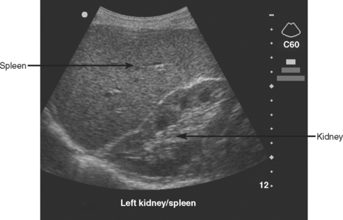
Figure 5 Normal sagittal view of left upper quadrant showing the hyperechoic left kidney/spleen interface.
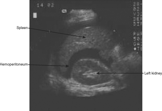
Figure 6 Sagittal view of left upper quadrant showing anechoic hemoperitoneum between left kidney and spleen.
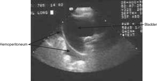
Finally, the transducer is placed transversely just above the symphysis pubis and directed inferiorly looking for a coronal view of the bladder. This is ideally done before bladder catheterization to allow for a distended bladder, which optimizes ultrasound transmission and detection of free fluid posterior to the bladder in the rectovesical/uterine space. If a catheter has previously been placed, saline can be injected into the bladder through the catheter, or the catheter can simply be clamped and the pelvic view obtained after passive filling. Free intra-abdominal fluid is best detected on longitudinal plane in the rectovesical or rectouterine space by an anechoic band between the bladder and uterus or rectum as shown in Figure 7.
TROUBLESHOOTING
Difficulties in image formation are often solved with the simple techniques and strategy changes found in Table 6. A common solution to improve visualization is to apply a liberal amount of gel and reapply whenever the image quality is poor. An image that is too dark or too bright may require an adjustment in the gain. Poor visualization of deeper structures may also require a lower-frequency (2.5-MHz) transducer or an increase in time-gain compensation of the far field. A 2.5-MHz transducer may be necessary for the obese trauma patient. A 5-MHz transducer may increase the resolution of FAST in pediatric trauma patients, and a 7.5-MHz transducer is optimal for superficial structures (vascular, soft tissue). Subcutaneous emphysema poses a significant problem for ultrasound waves and alternate sites such as the parasternal position may be necessary for adequate visualization.
| Problem | Solution |
|---|---|
| Image too dark | Increase gain, apply more gel |
| Image too bright | Decrease gain |
| Poor penetration of waves | Use lower-frequency transducer, increase gain, subcutaneous emphysema (use alternate site), apply more gel |
| Poor image | Adjust gain, higher frequency transducer, subcutaneous emphysema (use alternate site), inadequate gel, begin with light pressure, slow movements |
| Disorientation | Confirm correct surface anatomy, orient transducer position, find known landmark (e.g., liver, kidney) |
| Obesity | Use lower frequency transducer |
| Infants | Use higher frequency transducer |
| Pericardial | Gentle pressure beneath the xiphoid directing cephalad, use alternate left parasternal window, and with slow movements look for motion of heart |
| Right upper quadrant | Move up or down a rib space, move posterior, deep inspiration |
| Left upper quadrant | Place transducer as far posteriorly as possible (on bed) and direct anteriorly, insert an oro/nasogastric tube to decompress stomach gas, deep inspiration |
| Bladder | Ensure full bladder, clamp catheter or fill bladder with saline |
INDICATIONS
FAST should be performed on all trauma patients who require evaluation of the chest and abdomen and cannot be cleared by physical exam. It should not delay a patient with penetrating abdominal trauma and hypotension or peritonitis from surgical exploration. In the case of penetrating thoracoabdominal trauma, FAST is valuable in early identification of pericardial tamponade or hemoperitoneum. This early application of FAST can direct operative intervention toward the body cavity most likely injured.
FAST is indicated in the evaluation of the unstable, multitrauma patient with an unidentified cause of hypotension. In this scenario, CT is contraindicated and FAST provides a rapid screening test without moving the patient from the resuscitation area. A positive exam is most helpful in this situation and Rozycki et al.3 reported 100% sensitivity and specificity (8 of 8 patients) for intra-abdominal injury in patients with a positive FAST and hypotension. McKenney et al.,4 in a prospective evaluation of an ultrasound scoring system, reported similar results. In this series, 10 of 10 patients with initial hypotension (systolic blood pressure <90), and 32 of 36 patients with subsequent hemodynamic deterioration and a significant hemoperitoneum on FAST had a therapeutic laparotomy. Farahmand et al.,5 in a study of 128 hypotensive patients suffering blunt abdominal trauma found FAST to be indispensable. The sensitivity of FAST for all injuries was 85%, for surgical injuries 97%, and 100% for fatal injuries. The authors found that FAST was able to virtually exclude surgical injury and detect surgical injury in 64% of positive studies. These studies strongly suggest that the combination of hemoperitoneum and hypotension mandate urgent laparotomy. A negative exam in the multi-injured, hypotensive patient should prompt further aggressive diagnostic and therapeutic evaluation.
The portable and noninvasive nature of ultrasound permits repeat FAST evaluations. A secondary ultrasound is most important in patients without obvious blood loss, a negative primary FAST, and continued hemodynamic instability despite ongoing resuscitation. Secondary FAST may also be performed on patients where CT is unavailable or delayed. Recently, Blackbourne and colleagues6 prospectively evaluated 547 patients undergoing both a primary and secondary FAST exam (within 30 minutes to 24 hours of initial exam). Excluding patients with hemoperitoneum and hypotension (who went directly to the operating room), the secondary FAST exam increased the sensitivity of detecting intra-abdominal free fluid.
ACCURACY
Overall, FAST has proven to be an accurate, reliable, screening test for blunt trauma patients. Several large published series have reported sensitivity greater than 80% and specificity greater than 90%.3,7 Dolich and coworkers7 in a series of 2576 FAST studies reported a sensitivity of 86%, specificity of 98%, and an accuracy of 97%, with positive and negative predictive values of 87%, and 98%, respectively.
In a series of 1540 patients evaluated by FAST, Rozycki and colleagues3 reported a sensitivity of 83.3% and a specificity of 99.7%. Hypotension coupled with a positive FAST produced a 100% sensitivity and specificity for therapeutic operative intervention. In the same study, FAST was used to evaluate for hemopericardium in 313 patients with a sensitivity of 100% and specificity of 99.3%. This was followed by a multicenter study by Rozycki et al.8 examining 261 patients at risk for penetrating cardiac injury. They found a sensitivity, specificity, and accuracy of 100%, 96.9%, and 97.3%, respectively, for pericardial FAST.
While FAST for penetrating trauma to the pericardium has proven reliable, FAST for penetrating trauma to the abdomen has not been shown to be sensitive in detecting intra-abdominal injury. FAST for penetrating abdominal trauma is helpful only if it is positive; this group of patients should have immediate laparotomy. A negative FAST in penetrating abdominal injury is not helpful. It does, however, have excellent specificity and positive predictive value. Soffer et al.9 prospectively evaluated 177 stable patients with penetrating torso trauma and no clinical signs mandating operative exploration. They found FAST to have 48% sensitivity, 98% specificity, a negative predictive value (NPV) of 82%, a positive predictive value (PPV) of 92%, and an accuracy of 85%. The most common injury missed by FAST was hollow viscus injury. Interestingly, FAST altered the management in only three patients (1.7%) suggesting that it is not an accurate diagnostic tool. Similarly, Udobi and colleagues10 also reported the inadequacy of FAST to detect intra-abdominal injury in penetrating trauma. This prospective study included 75 stable patients, evaluated by FAST, without obvious indication for laparotomy. They reported sensitivity, specificity, NPV, and PPV of 46%, 94%, 60%, and 90%, respectively, for this patient population. In 72 patients without clear indication for laparotomy, Boulanger et al.11 reported similar results with FAST having a sensitivity, specificity, PPV, and NPV of 67%, 98%, 92%, and 89%, respectively. These investigators all conclude that a positive exam strongly suggests the need for laparotomy, and a negative exam requires additional diagnostic evaluation.
LEARNING CURVE AND TRAINING
The learning curve associated with FAST has been studied, and guidelines have been established for training and credentialing. In 1997, the World Consensus Conference on Ultrasound, consisting of an international expert panel of surgeons, radiologists, and emergency physicians, recommended the following training requirements: (1) 1-day training course consisting of a 4-hour didactic component followed by a 4-hour practical component, and (2) 200 supervised examinations.12 Alternative competency requirements exist consisting of a 1-day course followed by 50 supervised examinations.
Based on studies evaluating training and learning curves for nonradiologist clinicians, several conclusions and recommendations can be made. First, nonradiologist clinicians can learn and become competent with FAST techniques. McKenney et al.,13 in a prospective study comparing FAST accuracy of radiologists versus surgeons with limited training, found equal accuracy in interpreting FAST between both groups (99% vs. 99%). Thomas and colleagues14 determined that the overall accuracy of trainees following a 1-day FAST course was 98%, with a sensitivity of 81%, and a specificity of 91%. Multiple other investigators have shown that surgeons can achieve accuracy of over 90%, which compares favorably to radiologist performed FAST.3,7
Second, to the beginner, sensitivity is initially poor, but with experience, and after 25–100 examinations, the learning curve flattens and minimal improvement is seen beyond 100 examinations. This is controversial, however. McCarter and colleagues15 and Smith and colleagues16 have reported no identifiable learning curve among novice ultrasonographers and have suggested that 25 examinations are adequate. Other studies do show that sensitivity improves over the first 100 exams. Shackford and coworkers17 at the University of Vermont challenged the recommendation of more than 50 proctored examinations. In a prospective study, they observed a steep learning curve with a decrease in error rate from 17% after the first 5 examinations, to 5% after 10 examinations. Notably, this steep curve was observed among a selected group of patients with a high risk of hemoperitoneum (21.2%). Jang et al.18 found that 10 FAST examinations performed by emergency medicine residents was insufficient experience to ensure high sensitivity. After 20 examinations their sensitivity was 74%, but residents having 31 or more completed cases observed a rise in sensitivity to 95%.
Fourth, total number of exams is not the only important factor in acquiring this skill. It is important to include an adequate number of positive examinations during the training period. In large series by Dolich et al.7 and Rozycki and associates,3 the positive FAST rate is between 9% and 13%, and therefore, it may take 100 FAST examinations to be exposed to sufficient true positives to accurately recognize the varying degrees of a positive exam. In addition, with liberal application of FAST to all trauma patients, true negative rates will be high, possibly falsely elevating the sensitivity of the exam. It has been noted by several investigators that error rates increase with an increasing prevalence of hemoperitoneum.19 Peritoneal dialysis models for FAST training have been used to increase the experience in identifying positive studies. Gracias and colleagues20 found that sensitivity increased from 45% to 87% after training using peritoneal dialysis patients as a model.
FLUID VOLUME AND SCORING SYSTEMS
The differential diagnosis for free fluid within the abdomen found on FAST includes blood, urine, ascites, and bowel contents. Free fluid within the peritoneum has been shown to collect in the dependent regions of the abdomen: the right upper quadrant (Morrison’s pouch), left upper quadrant (perisplenic), and in the pelvis. The minimal volume of intra-abdominal fluid reliably detected by FAST is usually more than 500 ml, ranging from 250 to 620 ml.19 Abrams and colleagues21 have shown that 5 degrees of Trendelenburg positioning increases the sensitivity of FAST. In patients requiring DPL, Branney and colleagues22 found that a minimum of 619 ml was required for most examiners to detect free fluid within Morrison’s pouch. Sensitivity of detecting 1000 ml of intra-abdominal fluid in this study was 97%.
Early experience with FAST taught clinicians that patients with large volumes of hemoperitoneum were most likely to require laparotomy. Two scoring systems were developed to identify which patients were most likely to require operative exploration. Huang and colleagues23 gave 1 point for each of the five areas of the abdomen positive for blood, and an additional point for free-floating intestine. Two points were given for a fluid depth of greater than 2 mm in the hepatorenal or splenorenal space. They found that 96% of patients with 3 or more points required laparotomy; however, 38% of patients with a score less than 3 still required laparotomy. The sensitivity and specificity for hemoperitoneum greater than 1 liter at laparotomy was 84% and 71%, respectively.
McKenney and colleagues4 developed a second scoring system and prospectively evaluated its performance. Using this system, the ultrasound score was defined as the depth in centimeters of the deepest pocket of fluid collection, plus the number of additional spaces where fluid was seen. They found that 85% of patients with a score greater or equal to 3, and only 15% of patients with a score less than 3 required laparotomy. In addition, this score was found to be more accurate than systolic blood pressure and base deficit in identifying patients in need of operative exploration. The sensitivity, specificity, and accuracy of this scoring system was 83%, 87%, and 85%, respectively.
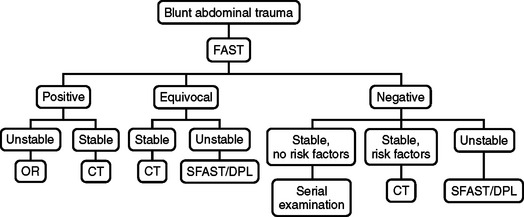
ALGORITHM: BLUNT ABDOMINAL TRAUMA
A negative FAST exam and instability should prompt further clinical and diagnostic evaluation (e.g., chest x-ray, diagnostic peritoneal lavage, anteroposterior pelvis x-ray, long-bone x-rays) to identify other potential sites of blood loss and a secondary FAST in 30 minutes. A negative FAST, stable vital signs, and risk factors for intra-abdominal injury should be followed up with CT or a secondary FAST if CT is unavailable. Risk factors for intra-abdominal injury include: spinal, pelvic, and rib fractures, hematuria, hypotension, abdominal tenderness, persistent base deficit, significant distracting injuries, head injury, and intoxication. Patients with these risk factors should have abdominal and pelvic CT. Ballard et al.24 found a high incidence of missed intra-abdominal injuries in patients evaluated by FAST with pelvic fractures. There were 13 of 70 false-negative FAST exams in patients with pelvic fractures leading to four therapeutic laparotomies and nine patients with solid organ injuries managed nonoperatively.
Patients with blunt abdominal trauma and an equivocal FAST are followed by CT in stable patients, or a secondary FAST or DPL if CT is unavailable. Unstable patients with an equivocal FAST are resuscitated and evaluated with routine trauma diagnostic evaluation (chest x-ray, anteroposterior pelvis x-ray, long-bone x-rays) and DPL or secondary FAST. If the DPL or secondary FAST remains equivocal, the patient should have immediate laparotomy. The algorithm for blunt abdominal trauma is presented in Figure 8.
ALGORITHM: PENETRATING THORACOABDOMINAL TRAUMA
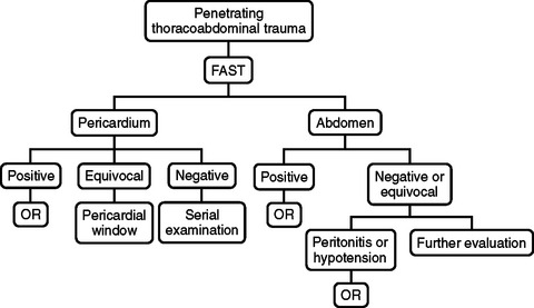
In patients with penetrating thoracoabdominal trauma, the accuracy of FAST in detecting hemopericardium is excellent, while the sensitivity of FAST in identifying intra-abdominal injury is poor. This is reflected in the FAST algorithm in Figure 9. Patients with penetrating thoracoabdominal trauma should have initial FAST to identify hemopericardium, hemothorax, or hemoperitoneum. FAST positive for hemopericardium warrants immediate median sternotomy and a hemothorax is managed with tube thorocostomy. In the presence of hemothorax, Rozycki et al.8 have reported false-positive and -negative results for pericardial FAST. The hemothorax may obscure identification of intrapericardial blood, or a perforation of the pericardium may allow blood from the heart to enter the thoracic cavity.
EXTENSIONS TO FAST
Hemothorax
Evaluation for hemothorax is an extension of the right and left upper quadrant regions of FAST. The 3.5-MHz transducer is slowly moved cephalad until the hyperechoic diaphragm is identified. The supradiaphragmatic region is examined for anechoic fluid surrounding a hypoechoic “floating lung.” There are obvious advantages to ultrasound diagnosis of hemothorax. As a part of FAST, detection of hemothorax is rapid and management decisions are expedited. Sisley et al.25 compared the accuracy of ultrasonography and chest radiography in the detection of traumatic hemothorax. Three hundred sixty patients were examined with a sensitivity of 97.4% and specificity of 99.7%, versus 92.5% sensitivity and 99.7% specificity for chest x-ray. They also reported a significantly faster performance time for ultrasound compared to chest x-ray.
Pneumothorax
FAST has been extended by some investigators to include evaluation for pneumothorax. This has been termed extended FAST (eFAST) or FAST +2. Again, similar to detection of hemothorax, ultrasound diagnosis for pneumothorax is a rapid, noninvasive, and accurate test. Dulchavsky et al.26 evaluated the performance of ultrasound in detecting pneumothorax in 382 trauma patients. Ultrasound identified 37 of 39 pneumothoraces (sensitivity 95%), with 2 pneumothoraces missed due to subcutaneous emphysema, and a true-negative rate of 100%. In a similar investigation, a group of emergency physicians27 examined 176 patients for pneumothorax using ultrasound and compared their findings to CT. Using CT as the gold standard they found that ultrasound outperformed chest radiography in the detection of pneumothorax (sensitivity 98% vs. 76%). These groups have concluded that ultrasound is a rapid and accurate modality for pneumothorax recognition, but still recommend routine chest x-ray for trauma patient evaluation.
Sternal Fracture
Using a 7.5-MHz transducer, sternal fractures can be diagnosed with accuracy comparable to lateral sternal x-ray. Mahlfeld et al.28 described the use of ultrasound in 11 patients suspected of sustaining a sternal fracture. In all 11 cases the fracture was detected by ultrasound and confirmed by lateral x-ray. Advantages to ultrasound diagnosis include its speed and apparent accuracy. Subcutaneous emphysema secondary to pneumothorax occasionally prevents adequate assessment of the sternum. Sternal fracture is rarely, if ever, life threatening and routine screening for this fracture is unlikely to become a part of the FAST protocol. However, it is important to recognize the degree of force required to fracture the sternum and the potential for associated thoracic and mediastinal injuries.
FAST FOR PEDIATRIC TRAUMA
The accuracy of FAST for pediatric blunt trauma patients is comparable to the adult blunt trauma population. In a prospective study, Thourani and colleagues29 followed 196 pediatric trauma patients and found FAST to be 80% sensitive and 100% specific. In this study, FAST was positive in 5.3%, confirming the low frequency of hemoperitoneum in the pediatric trauma population. Four patients required immediate laparotomy after FAST and there were two false negatives confirmed on delayed CT; neither of these patients required laparotomy. All three patients with positive FAST and hypotension required therapeutic operative intervention. Five of five hemodynamically stable patients with positive FAST had splenic lacerations confirmed by CT and managed nonoperatively. These authors also found that the surgeon-sonographers were capable of performing FAST with adequate accuracy and the 3.5-MHz probe produced acceptable images. They concluded that FAST provides a rapid, accurate screening tool for pediatric trauma patients and provides efficient assessment of the abdomen allowing prioritization of injuries.
Soudack et al.30 retrospectively reviewed 313 pediatric trauma patients evaluated by FAST. They reported 39 positive FAST exams with three false negatives and two false positives, with an overall sensitivity of 92.5%, specificity of 97.2%, and accuracy of 95.5%. They concluded that FAST was an effective screening tool. Coley et al.31 in a report of 32 pediatric patients reported a sensitivity of only 55%; however, this study only included hemodynamically stable patients. Holmes et al.32 studied FAST in 224 hemodynamically stable and unstable pediatric trauma patients. They report a sensitivity and specificity of 82% and 95%, respectively, for all patients. Seven of seven patients with positive FAST and hypotension had confirmed intra-abdominal injury at laparotomy. In total, 18 patients with positive FAST were taken to the operating room and only one patient had a nontherapeutic laparotomy. Fifteen patients in this study had a negative FAST and were determined to have intra-abdominal injury, six with intraperitoneal fluid and nine without intraperitoneal fluid. Two of these false negative exams included gastrointestinal tract injuries. They concluded that FAST is a rapid, accurate screening test and provides crucial information for the management of the hypotensive pediatric trauma patient. They also emphasize the need for CT in hemodynamically stable children with a positive FAST and in children where intra-abdominal injury cannot be ruled out by physical exam.
Ultrasound scoring systems have also been applied to the pediatric trauma population. Using the McKenney score, Ong et al.33 retrospectively reviewed 193 pediatric trauma patients who had FAST. Thirty-seven patients had an initial positive FAST exam, with 22 patients scoring less than 3 and 15 patients scoring greater than or equal to 3. Of the 15 patients with a score greater than or equal to 3, eight required therapeutic laparotomy compared to only 1 of 22 in the group scoring less than 3. Interestingly, this patient had a jejunal perforation and mesenteric bleeding. One nontherapeutic laparotomy was performed in each group. The sensitivity, specificity, and accuracy for predicting therapeutic laparotomy using the McKenney score in this study was 89%, 75%, and 78%, respectively.
FAST FOR REPRODUCTIVE-AGE FEMALES
In reproductive-age female trauma patients, free fluid within the abdomen and pelvis detected by FAST suggests intra-abdominal injury until proven otherwise. Physiologic free fluid on transabdominal ultrasound has been estimated to range from 5–21 ml.34 Ormsby et al.34 reviewed 328 pregnant and 1804 reproductive-age women who presented with blunt abdominal trauma and were evaluated with FAST. Overall, they found that free fluid in the abdomen alone or abdomen and pelvis was strongly correlated with intra-abdominal injury compared to those with a negative FAST. In patients with free fluid in the abdomen alone, 57 of 70 (81.4%) nonpregnant and 4 of 9 (44%) pregnant patients had intra-abdominal injury. Of those with free fluid in the abdomen and pelvis, 67 of 74 (91%) nonpregnant and 7 of 10 (70%) pregnant patients had intra-abdominal injuries. Notably, 17 of 43 (40%) nonpregnant and 3 of 10 (30%) pregnant patients with free fluid isolated to the pelvis suffered intra-abdominal injury and the authors cautioned that isolated free fluid not be considered physiological in trauma patients. They also emphasized the need for a full bladder to visualize the pelvis adequately. In this study, 67 of 1804 (3.7%) nonpregnant patients, and 9 of 299 (3%) pregnant patients had a false-negative FAST, suggesting very good sensitivity of FAST in this patient population. Six of nine pregnant patients with intra-abdominal injury and a negative FAST had placental abruption. This underscores the need for obstetrical consultation and fetal monitoring in this unique trauma population. FAST in pregnant patients may have a lower sensitivity for detecting intraabdominal injury. Richards et al.35 reported FAST results from 328 pregnant patients. Twenty-three pregnant patients were FAST positive with a sensitivity, specificity, and accuracy of 61%, 94%, and 92%, respectively. Bochicchio and colleagues36 have also suggested the FAST protocol should include routine screening in reproductive-age females for pregnancy. They confirmed pregnancy in 126 of 132 patients who reported that they were pregnant on admission, and diagnosed 8 incidental pregnancies using FAST alone.
LIMITATIONS OF FAST
The primary goal of FAST is to identify hemopericardium, hemothorax, and hemoperitoneum, and is not a detailed evaluation of the heart, lungs, and solid organs of the abdomen. FAST protocols do not evaluate for injury to solid organ parenchyma, the gastrointestinal tract, the diaphragm, or retroperitoneal structures. Therefore, the major limitation of FAST is the detection of injuries that do not produce significant free intracavitary fluid. Intestinal injuries are a major limitation for FAST; the sensitivity of ultrasound in detecting intestinal injuries is poor. In a 15-year retrospective review of 1239 patients, Yoshii et al.37 found that the overall sensitivity, specificity, and accuracy of ultrasound was 95%, 95%, and 95%, respectively. Individual organ injuries were identified with sensitivities of 92%, 90%, 92%, 71%, and 35% for the liver, spleen, kidneys, pancreas, and intestine, respectively. These authors concluded that ultrasound is a reliable method of diagnosing solid organ injuries, but insensitive for detecting intestinal injury.
CONTROVERSIES
Controversial issues surrounding FAST include whether nonradiologist clinicians can or should use ultrasonography. This question has been answered by large studies. Surgeon-performed FAST has been validated and shown to be a rapid, accurate, and useful screening modality.3,7 Training requirements have been established by an international consensus conference,12 and prospective studies have shown accuracy comparable to our radiology colleagues.13 What constitutes an adequate number of examinations or volume of experience depends on a number of factors. Total number of exams, proctored evaluations, and number of positive studies all impact the learning curve of surgeon-performed FAST. As previously stated, it appears that 25–100 proctored studies evaluating multitrauma patients provides an adequate learning experience.
DPL has been essentially replaced by FAST. Although there has not been a randomized prospective trial comparing DPL to FAST, there remains little doubt that FAST is faster, less invasive, and carries less risk for procedure related morbidity. In a prospective study comparing FAST to DPL, Lentz et al.38 examined 54 patients with FAST and subsequently DPL. They found that FAST compared favorably with sensitivity of 87%, specificity of 100%, and accuracy of 96% for detecting free intraperitoneal fluid. Previously, the sensitivity of DPL (>95%) had led to a high rate of negative laparotomy. With the advent of CT and FAST, the rate of negative laparotomy has decreased, but DPL is still a useful tool in the evaluation of FAST-negative, unstable patients with an undetermined source of hypotension (see Figure 8).
As the reliability, accuracy, cost-effectiveness, and training of surgeon-performed FAST have been established, some have questioned whether FAST can replace CT in certain patient populations. Certainly, hemodynamically unstable patients should not have CT, and FAST is an important tool in the evaluation of this group. The known risk factors for intra-abdominal injury in FAST-negative patients are rib, pelvic, and spinal fractures; brief hypotension; hematuria; intoxication; persistent base deficit; head injury; distracting injury; and abdominal tenderness. These patients should have CT to further evaluate the abdomen and pelvis. Ballard et al.24 found FAST to be only 24% sensitive in detecting free abdominal fluid in patients with pelvic fractures. Four of the 13 false-negative patients in this group required operative intervention and the remaining 9 patients were successfully managed nonoperatively. In this study, FAST was compared to CT for patients with spinal injuries, but the data were insufficient for any recommendations. Other conditions that preclude detection of intra-abdominal injury by physical examination include intoxication, head injury, distracting injuries, and a persistent base deficit. Patients in this group commonly require CT, leaving a group of patients that can be reliably followed by clinical exam. Rose et al.39 reported a study randomizing patients to receive either FAST or control (no FAST) to determine whether routine ultrasonography affected use of CT. A total of 104 patients were analyzed in each group, but the study was concluded early because an interim review recognized that FAST was becoming standard practice. Nevertheless, 52% of the control group and 36% of the FAST group received CT. The FAST group had sensitivity, specificity, and accuracy of 80%, 98%, and 96%, respectively. In the FAST group, three patients with a negative FAST and no CT had an intra-abdominal injury. Two of these three patients ultimately required therapeutic laparotomy. There were no missed injuries among patients receiving CT. Routine indications for CT after FAST included known risk factors for intra-abdominal injury, but this was not required per protocol. This trial did show a decrease in the use of CT with routine FAST, but the sample size was too small to make any firm conclusions. In the Netherlands, Bakker et al.40 employed FAST as the primary screening tool in 1149 blunt abdominal trauma patients. Abdominal CT was employed in 7% resulting in delayed diagnosis of injury in 1.7% of patients without significant additional morbidity. Current practice suggests routine CT following FAST for stable patients with risk factors for intra-abdominal injury and where the abdominal examination is unreliable (see Figure 8).
The use of FAST in penetrating abdominal trauma is controversial. As mentioned previously, the sensitivity of FAST is 46%–67%9–11 in detecting penetrating intra-abdominal injury. However, the reliability of a positive FAST is excellent, having a positive predictive value of 90%–92%, and specificity of 94%–98%.9–11 Early application of FAST can also direct operative intervention toward the body cavity most likely injured resulting from single or multiple penetrating injuries. It must be emphasized, however, that a negative FAST does not rule out a significant intra-abdominal injury in penetrating trauma, and FAST must not delay operative intervention in patients with hypotension or peritonitis (see Figure 9). Decision making for operative intervention in penetrating abdominal trauma relies on clinical findings and FAST infrequently alters management. However, for penetrating injury to the pericardium, FAST has been shown to be over 96% sensitive, specific, and accurate.8
The presence of unstable pelvic fractures and free fluid on FAST is another area of controversy. Free fluid in this setting may be secondary to transperitoneal decompression of pelvic retroperitoneal blood or to concomitant intra-abdominal injuries. However, the rate of intraabdominal injury and pelvic fracture in this patient population has been reported to be 67%. Ruchholtz et al.41 reviewed 80 patients with AO/SICOT classification type B or type C pelvic ring fractures and FAST. Thirty-one patients had positive FAST, and 49 patients had negative FAST. Thirty of 31 patients with positive FAST had intraabdominal or urogenital organ injury requiring surgical repair (2 patients with extraperitoneal bladder rupture in this group would probably have been managed nonoperatively in the United States). Twelve of 15 patients who presented with unstable pelvic ring fracture, hypotension, and positive FAST required therapeutic laparotomy. In the group of 49 patients with negative FAST, 3 required initial laparotomy (1 for perianal disruption, 1 for extraperitoneal disruption). An additional 3 patients required delayed laparotomy, 1 patient required splenectomy for ongoing bleeding, 1 patient developed abdominal compartment syndrome, and 1 patient had a delayed diagnosis and repair of the diaphragm. Although the sensitivity for detecting abdominal lesions with FAST in patients with type-B or -C pelvic ring fractures was 75% in this study, the positive predictive value of finding a relevant intra-abdominal/urogenital lesion was 97%. There was only positive FAST, due to transperitoneal blood from a pelvic fracture, which led to a nontherapeutic laparotomy. These authors report that positive FAST, in the setting of unstable type-B and -C pelvic fractures, strongly correlates with significant intra-abdominal/urogenital lesions requiring early laparotomy.
1 Rozycki GS, et al. Early detection of hemoperitoneum by ultrasound examination of the right upper quadrant: a multicenter study. J Trauma. 1998;5:878.
2 GS Rozycki, et al: Surgeon-performed ultrasound in trauma and surgical critical care. In Moore EE, Feliciano DV, Mattox KL, editors: Trauma, 5 ed. New York, McGraw-Hill, pp. 311–328
3 Rozycki GS, et al. Surgeon-performed ultrasound for the assessment of truncal injuries: lessons learned from 1540 patients. Ann Surg. 1998;228:557.
4 McKenney KL, et al. Hemoperitoneum score helps determine need for therapeutic laparotomy. J Trauma. 2001;50:650.
5 Farahmand N, et al. Hypotensive patients with blunt abdominal trauma: performance of screening US. Radiology. 2005;235:436.
6 Blackbourne LH, et al. Secondary ultrasound examination increases the sensitivity of the FAST exam in blunt trauma. J Trauma. 2004;57:934.
7 Dolich MO, et al. 2,576 Ultrasounds for blunt abdominal trauma. J Trauma. 2001;50:108.
8 Rozycki GS, et al. The role of ultrasound in patients with possible penetrating cardiac wounds: a prospective multicenter study. J Trauma. 1999;46:543.
9 Soffer D, et al. A prospective evaluation of ultrasonography for the diagnosis of penetrating torso injury. J Trauma. 2004;56:953.
10 Udobi KF, et al. Role of ultrasonography in penetrating abdominal trauma: a prospective clinical study. J Trauma. 2001;50:475.
11 Boulanger BR, et al. The routine use of sonography in penetrating torso injury is beneficial. J Trauma. 2001;51:320.
12 Scalea TM, et al. Focused assessment with sonography for trauma (FAST): results from an international consensus conference. J Trauma. 1999;46:466.
13 McKenney MG, et al. Can surgeons evaluate emergency ultrasound scans for blunt abdominal trauma? J Trauma. 1998;44:649.
14 Thomas B, et al. Ultrasound evaluation of blunt abdominal trauma: program implementation, initial experience, and learning curve. J Trauma. 1997;42:384.
15 McCarter FD, et al. Institutional and individual learning curves for ocused abdominal ultrasound for trauma: cumulative sum analysis. Ann Surg. 2000;231:689.
16 Smith RS, et al. Institutional learning curve of surgeon-performed trauma ultrasound. Arch Surg. 1998;133:530.
17 Shackford SR, et al. Focused abdominal sonogram for trauma: the learning curve of nonradiologist clinicians in detecting hemoperitoneum. J Trauma. 1999;46:553.
18 Jang T, et al. Residents should not independently perform focused abdominal sonography for trauma after 10 training examinations. J Ultrasound Med. 2004;23:793.
19 Rose JS. Ultrasound in abdominal trauma. Emerg Med Clin North Am. 2004;22:581.
20 Gracias VH, et al. The role of positive examinations in training for the Focused Assessment Sonogram in Trauma (FAST) examination. Am Surg. 2002;68:1008.
21 Abrams BJ, et al. Ultrasound for the detection of intraperitoneal fluid: the role of Trendelenberg positioning. Am J Emerg Med. 1999;17:117.
22 Branney SW, et al. Quantitative sensitivity of ultrasound in detecting free intraperitoneal fluid. J Trauma. 1995;39:375.
23 Huang M, et al. Ultrasonography for the evaluation of hemoperitoneum during resuscitation: a simple scoring system. J Trauma. 1994;36:173.
24 Ballard RB, et al. An algorithm to reduce the incidence of false-negative FAST examinations in patients at high risk for occult injury. J Am Coll Surg. 1999;189:145.
25 Sisley AC, et al. Rapid detection of traumatic effusion using surgeon-performed ultrasonography. J Trauma. 1998;44:291.
26 Dulchavsky SA, et al. Prospective evaluation of thoracic ultrasound in the detection of pneumothorax. J Trauma. 2001;50:201.
27 Blaivas M, et al. A prospective comparison of supine chest radiography and bedside ultrasound for the diagnosis of traumatic pneumothorax. Acad Emerg Med. 2005;12:844.
28 Mahlfeld A, et al. Ultrasound diagnosis of sternal fractures. Zentrabl Chir. 2001;126:62.
29 Thourani VH, et al. Validation of surgeon-performed emergency abdominal ultrasonography in pediatric trauma patients. J Pediatr Surg. 1998;33:322.
30 Soudack M, et al. Experience with Focused Abdominal Sonography for Trauma (FAST) in 313 pediatric patients. J Clin Ultrasound. 2004;32:53.
31 Coley BD, et al. Focused Abdominal Sonography for Trauma (FAST) in children with blunt abdominal trauma. J Trauma. 2000;48:902.
32 Holmes JF, et al. Emergency department ultrasonography in the evaluation of hypotensive and normotensive children with blunt abdominal trauma. J Pediatr Surg. 2001;36:968.
33 Ong AW, et al. Predicting the need for laparotomy in pediatric trauma patients on the basis of the ultrasound score. J Trauma. 2003;54:503.
34 Ormsby EL, et al. Pelvic free fluid: clinical importance for reproductive age women with blunt abdominal trauma. Ultrasound Obstet Gynecol. 2005;26:271.
35 Richards JR, et al. Blunt abdominal injury in the pregnant patient: detection with ultrasound. Radiology. 2004;233:463.
36 Bochicchio GV, et al. Surgeon-performed focused assessment with sonography for trauma as an early screening tool for pregnancy after trauma. J Trauma. 2002;52:1125.
37 Yoshii H, et al. Usefulness and limitations of ultrasonography in the initial evaluation of blunt abdominal trauma. J Trauma. 1998;45:45.
38 Lentz KA, et al. Evaluating blunt abdominal trauma: role for ultrasonography. J Ultrasound Med. 1996;15:447.
39 Rose JS, et al. Does the presence of ultrasound really affect computed tomographic scan use? A prospective randomized trial of ultrasound in trauma. J Trauma. 2001;51:545.
40 Bakker J, et al. Sonography as the primary screening method in evaluating blunt abdominal trauma. J Clin Ultrasound. 2005;33:155.
41 Ruchholtz S, et al. Free abdominal fluid on ultrasound in unstable pelvic ring fracture: is laparotomy always necessary? J Trauma. 2004;57:278.
[/level-membership-for-critical-care-medicine-category][not-level-membership-for-critical-care-medicine-category]
CHAPTER 20 THE ROLE OF FOCUSED ASSESSMENT WITH SONOGRAPHY FOR TRAUMA: INDICATIONS, LIMITATIONS, AND CONTROVERSIES
Focused Assessment with Sonography for Trauma (FAST) has rapidly taken root in modern trauma care. FAST is an integral part of trauma algorithms, and is an important adjunct to the Advanced Trauma Life Support (ATLS) primary and secondary surveys. In 1997, the American Board of Surgery required the addition of ultrasonography into Accreditation Council for Graduate Medical Education (ACGME)–approved surgical training programs. The American College of Surgeons (ACS) has also incorporated FAST into the ATLS course and has sponsored multiple ultrasound training seminars.
FORMATION OF AN ULTRASOUND IMAGE
Proper visualization and accurate interpretation of an ultrasound image requires a basic understanding of ultrasound components, principles, physics, and terminology. The basic components of an ultrasound machine are listed in Table 1 and include the transmitter to send electrical signals to the transducer, the transducer to interconvert electrical energy and acoustic energy using the piezoelectric effect, the receiver to convert electrical signals into an image, and the monitor to display the image. An optional printer provides a hardcopy image.
| Component | Description |
|---|---|
| Transmitter | Sends electrical signals to transducer |
| Transducer | Interconverts electrical energy and acoustic energy by piezoelectric effect |
| Receiver | Converts electrical signals into image |
| Monitor | Displays image |
| Printer | Records hard copy of image (optional) |
There are three essential principles of ultrasonography (Table 2): the piezoelectric effect, pulse-echo principle, and acoustic impedance. Within the transducer, piezoelectric crystals expand and contract to interconvert electrical and mechanical energy, a process known as the piezoelectric effect. When an ultrasound wave contacts tissue, some of the signal is reflected and some is transmitted into tissue. The reflected waves bounce back and contact the crystals within the transducer, generating electrical impulses comparable to the strength of the returning wave. This is known as the pulse–echo principle. Acoustic impedance is the density of tissue multiplied by the speed of sound in tissue. The strength of the returning echo depends on the difference in density between the two structures imaged. Structures of different acoustic impedance (e.g., bile and gallstones) are relatively easy to distinguish from one another, whereas those of similar acoustic impedance (e.g., spleen and kidney) are more difficult to distinguish.1
Table 2 Essential Principles of Ultrasound
| Principle | Explanation |
|---|---|
| Piezoelectric effect | Piezoelectric crystals expand and contract to interconvert electrical and mechanical energy. |
| Pulse-echo principle | When an ultrasound wave contacts tissue, some of the signal is reflected and some is transmitted into tissue. These waves are then reflected to crystals within the transducer, generating electrical impulse comparable to the strength of the returning wave. |
| Acoustic impedance | Acoustic impedance is the density of tissue X speed of sound in tissue. The strength of the returning echo depends on the difference in density between the two structures imaged: structures of different acoustic impedance (e.g., bile and gallstones) are relatively easy to distinguish from one another, whereas those of similar acoustic impedance (e.g., spleen and kidney) are more difficult to distinguish. |
The basic physics of ultrasonography are important for good image formation, and terminology used for ultrasonography is listed in Table 3. Ultrasound waves are high-frequency (>20 kHz) mechanical radiant energy transmitted through a medium. The frequency (number of cycles/second) of medical diagnostic ultrasound is 2.5–10 MHz. As frequency increases, resolution improves, but penetration to deeper tissue decreases. Generally, the highest frequency transducer that produces the best resolution of the target organ is chosen (3.5 MHz for FAST). Common clinical applications of different ultrasound frequencies are listed in Table 4.
Table 3 Ultrasound Terminology
| Term | Definition |
|---|---|
| Ultrasound | High-frequency (>20 kHz) mechanical radiant energy transmitted through a medium |
| Frequency | Number of cycles per second (medical diagnostic ultrasound: 2.5–10 MHz) |
| Propagation speed | Speed at which wave travels through soft tissue (1540 m/sec) |
| Amplitude | Strength or height of wave |
| Attenuation | Decrease in amplitude and intensity of wave as it travels through medium |
| Absorption | Conversion of sound waves into heat |
| Scattering | Redirection of wave as it strikes rough or small boundary |
| Reflection | Return of wave toward transducer |
| Artifact | Error in imaging |
| Gain | Amplitude of returning waves based on tissue depth |
Table 4 Clinical Applications of Selected Transducer Frequencies
| Frequency | Application |
|---|---|
| 2.5–3.5 MHz | General abdominal |
| 5 MHz | Transvaginal, pediatric abdominal, testicular |
| 7.5 MHz | Vascular, soft tissue, thyroid |
The echogenicity of a structure is defined as the degree to which tissue echoes ultrasonic waves (generally reflected in ultrasound images as the degree of brightness). Tissues that reflect waves strongly will appear bright and are hyperechoic. Tissues that conduct ultrasound waves well are hypoechoic and are darker, while anechoic tissues conduct waves very well and appear black because essentially no waves are reflected back to the transducer. Isoechoic tissue transmits ultrasound similar to that of surrounding tissues, and is displayed with similar intensity (Table 5).1
Table 5 Terminology Used in Interpretation of Ultrasound Images
| Term | Definition |
|---|---|
| Echogenicity | Degree to which tissue echoes ultrasonic waves (generally reflected in ultrasound image as degree of brightness) |
| Anechoic | No internal echoes, appearing dark or black |
| Isoechoic | Having appearance similar to that of surrounding tissue |
| Hypoechoic | Less echoic (darker) than surrounding tissue |
| Hyperechoic | More echoic (brighter) than surrounding tissue |
TECHNIQUE
The patient’s identifying information is first entered to annotate the hardcopy ultrasound images. With the patient in the supine position, a liberal amount of ultrasound transmission gel is applied to the subxiphoid, left and right upper quadrants, and suprapubic areas. Using four transducer positions as shown in Figure 1, the pericardium and five dependent abdominal regions are examined for free fluid:
Although Morrison’s pouch was shown by Rozycki and colleagues2 to be the most sensitive for free intra-abdominal fluid, all five regions of the abdomen should be examined to maximize sensitivity of the test. Each area should be evaluated in two planes (longitudinal and transverse) with confirmation of positive regions using two views.
A 3.5-MHz convex transducer is oriented for sagittal sections and positioned in the subxiphoid area directing the transducer superiorly. Often, mild pressure on the transducer below the xiphoid toward the pericardial sac is required to visualize the heart. If this is unsuccessful, a left, parasternal, 4th or 5th intercostal view will be required. Obesity, rib/sternal fracture, subcutaneous emphysema, and a narrow subcostal angle may necessitate the parasternal view, and/or make this part of the examination indeterminate. Hemopericardium is detected by an anechoic band between the heart and the pericardial/diaphragmatic interface, as seen in Figure 2.
The right upper quadrant is then visualized by placing the transducer in the right mid to posterior axillary line, 11th intercostal space, in both longitudinal and transverse planes to visualize the right subdiaphragmatic and hepatorenal interface. An anechoic band between the liver and kidney as shown in Figure 3 identifies the presence of a minimal amount of blood, and a moderate hemoperitoneum is shown in Figure 4.
The left upper quadrant is examined by directing the transducer between the 10th and 11th ribs in the posterior axillary line. The right sub-diaphragmatic and splenorenal spaces are examined in two planes for free fluid, detected again by an anechoic band separating the two organs. A normal view of the hyperechoic left kidney/spleen interface is shown in Figure 5 and a positive left upper quadrant view is shown in Figure 6.
Figure 5 Normal sagittal view of left upper quadrant showing the hyperechoic left kidney/spleen interface.
Figure 6 Sagittal view of left upper quadrant showing anechoic hemoperitoneum between left kidney and spleen.
Finally, the transducer is placed transversely just above the symphysis pubis and directed inferiorly looking for a coronal view of the bladder. This is ideally done before bladder catheterization to allow for a distended bladder, which optimizes ultrasound transmission and detection of free fluid posterior to the bladder in the rectovesical/uterine space. If a catheter has previously been placed, saline can be injected into the bladder through the catheter, or the catheter can simply be clamped and the pelvic view obtained after passive filling. Free intra-abdominal fluid is best detected on longitudinal plane in the rectovesical or rectouterine space by an anechoic band between the bladder and uterus or rectum as shown in Figure 7.
TROUBLESHOOTING
Difficulties in image formation are often solved with the simple techniques and strategy changes found in Table 6. A common solution to improve visualization is to apply a liberal amount of gel and reapply whenever the image quality is poor. An image that is too dark or too bright may require an adjustment in the gain. Poor visualization of deeper structures may also require a lower-frequency (2.5-MHz) transducer or an increase in time-gain compensation of the far field. A 2.5-MHz transducer may be necessary for the obese trauma patient. A 5-MHz transducer may increase the resolution of FAST in pediatric trauma patients, and a 7.5-MHz transducer is optimal for superficial structures (vascular, soft tissue). Subcutaneous emphysema poses a significant problem for ultrasound waves and alternate sites such as the parasternal position may be necessary for adequate visualization.
| Problem | Solution |
|---|---|
| Image too dark | Increase gain, apply more gel |
| Image too bright | Decrease gain |
| Poor penetration of waves | Use lower-frequency transducer, increase gain, subcutaneous emphysema (use alternate site), apply more gel |
| Poor image | Adjust gain, higher frequency transducer, subcutaneous emphysema (use alternate site), inadequate gel, begin with light pressure, slow movements |
| Disorientation | Confirm correct surface anatomy, orient transducer position, find known landmark (e.g., liver, kidney) |
| Obesity | Use lower frequency transducer |
| Infants | Use higher frequency transducer |
| Pericardial | Gentle pressure beneath the xiphoid directing cephalad, use alternate left parasternal window, and with slow movements look for motion of heart |
| Right upper quadrant | Move up or down a rib space, move posterior, deep inspiration |
| Left upper quadrant | Place transducer as far posteriorly as possible (on bed) and direct anteriorly, insert an oro/nasogastric tube to decompress stomach gas, deep inspiration |
| Bladder | Ensure full bladder, clamp catheter or fill bladder with saline |
INDICATIONS
FAST should be performed on all trauma patients who require evaluation of the chest and abdomen and cannot be cleared by physical exam. It should not delay a patient with penetrating abdominal trauma and hypotension or peritonitis from surgical exploration. In the case of penetrating thoracoabdominal trauma, FAST is valuable in early identification of pericardial tamponade or hemoperitoneum. This early application of FAST can direct operative intervention toward the body cavity most likely injured.
FAST is indicated in the evaluation of the unstable, multitrauma patient with an unidentified cause of hypotension. In this scenario, CT is contraindicated and FAST provides a rapid screening test without moving the patient from the resuscitation area. A positive exam is most helpful in this situation and Rozycki et al.3 reported 100% sensitivity and specificity (8 of 8 patients) for intra-abdominal injury in patients with a positive FAST and hypotension. McKenney et al.,4 in a prospective evaluation of an ultrasound scoring system, reported similar results. In this series, 10 of 10 patients with initial hypotension (systolic blood pressure <90), and 32 of 36 patients with subsequent hemodynamic deterioration and a significant hemoperitoneum on FAST had a therapeutic laparotomy. Farahmand et al.,5 in a study of 128 hypotensive patients suffering blunt abdominal trauma found FAST to be indispensable. The sensitivity of FAST for all injuries was 85%, for surgical injuries 97%, and 100% for fatal injuries. The authors found that FAST was able to virtually exclude surgical injury and detect surgical injury in 64% of positive studies. These studies strongly suggest that the combination of hemoperitoneum and hypotension mandate urgent laparotomy. A negative exam in the multi-injured, hypotensive patient should prompt further aggressive diagnostic and therapeutic evaluation.
The portable and noninvasive nature of ultrasound permits repeat FAST evaluations. A secondary ultrasound is most important in patients without obvious blood loss, a negative primary FAST, and continued hemodynamic instability despite ongoing resuscitation. Secondary FAST may also be performed on patients where CT is unavailable or delayed. Recently, Blackbourne and colleagues6
[/not-level-membership-for-critical-care-medicine-category]
