The radiographic image
Introduction
• Basic physics and equipment – the production of X-rays, their properties and interactions which result in the formation of the radiographic image
• Radiation protection – the protection of patients and dental staff from the harmful effects of X-rays
• Radiography – the techniques involved in producing the various radiographic images
• Radiology – the interpretation of these radiographic images.
Understanding the radiographic image is central to the entire subject. This chapter provides an introduction to the nature of this image and to some of the factors that affect its quality and perception.
Nature of the radiographic image
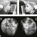
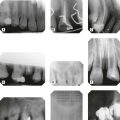
However the final image is captured, it can be described as a two-dimensional picture made up of a variety of black, white and grey superimposed shadows and is thus sometimes referred to as a shadowgraph (see Fig. 1.1).
• The three-dimensional anatomical tissues
• The limitations imposed by a two-dimensional picture and superimposition.
The radiographic shadows
• The white or radiopaque shadows on a film represent the various dense structures within the object which have totally stopped the X-ray beam.
• The black or radiolucent shadows represent areas where the X-ray beam has passed through the object and has not been stopped at all.
• The grey shadows represent areas where the X-ray beam has been stopped to a varying degree.
The final shadow density of any object is thus affected by:
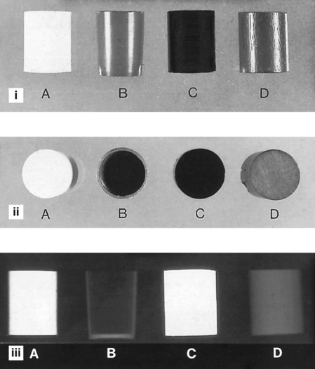
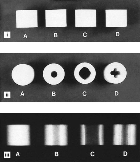
• The specific type of material of which the object is made
• The thickness or density of the material
• The intensity of the X-ray beam used
• The position of the object in relation to the X-ray beam and image receptor
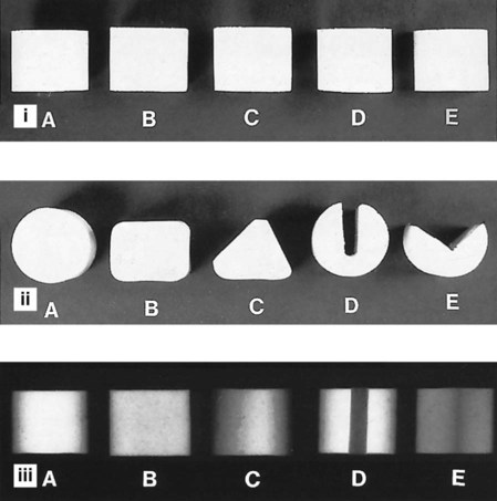
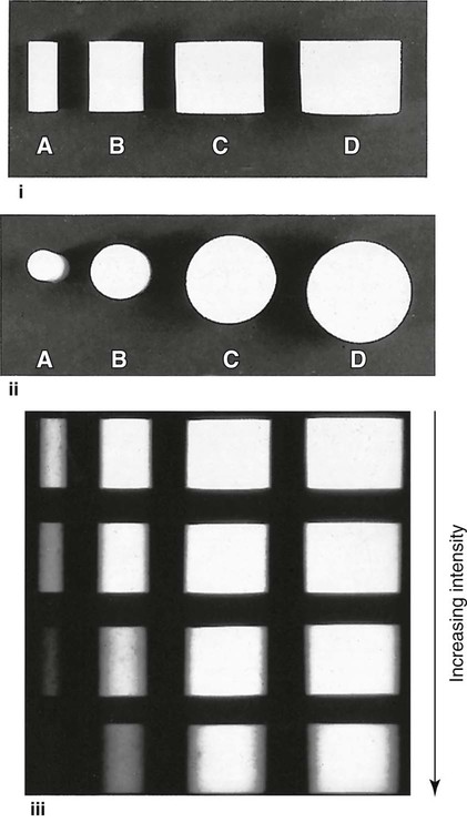
The effect of different materials, different thicknesses/densities, different shapes and different X-ray beam intensities on the radiographic image shadows are shown in Figs 1.2–1.5.
The three-dimensional anatomical tissues
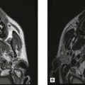
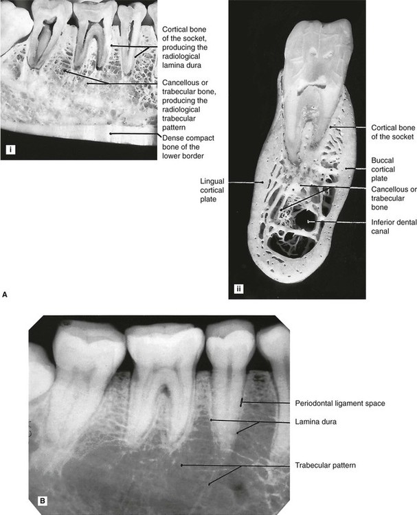
The shape, density and thickness of the patient’s tissues, principally the hard tissues, must also affect the radiographic image. Therefore, when viewing two-dimensional radiographic images, the three-dimensional anatomy responsible for the image must be considered (see Fig. 1.6). A sound anatomical knowledge is obviously a prerequisite for radiological interpretation (see Ch. 19).
The limitations imposed by a two-dimensional image and superimposition
The main limitations of viewing the two-dimensional image of a three-dimensional object are:
• Appreciating the overall shape of the object
• Superimposition and assessing the location and shape of structures within an object.
Appreciating the overall shape
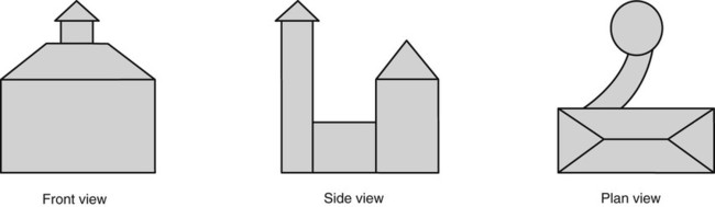
To visualize all aspects of any three-dimensional object, it must be viewed from several different positions. This can be illustrated by considering an object such as a house, and the minimum information required if an architect is to draw all aspects of the three-dimensional building in two dimensions (see Fig. 1.7). Unfortunately, it is only too easy for the observer to forget that teeth and patients are three-dimensional. To expect one radiograph to provide all the required information about the shape of a tooth or a patient is like asking the architect to describe the whole house from the front view alone.
Superimposition and assessing the location and shape of structures within an object
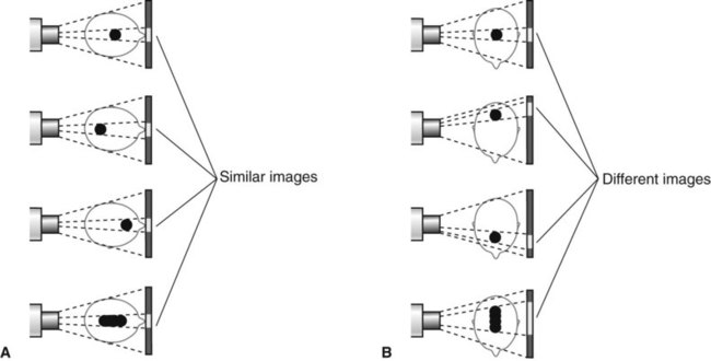
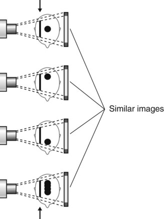
The shadows cast by different parts of an object (or patient) are superimposed upon one another on the final radiograph. The image therefore provides limited or even misleading information as to where a particular internal structure lies, or to its shape, as shown in Fig. 1.8.
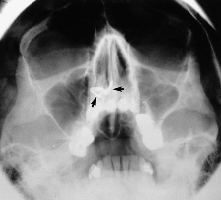
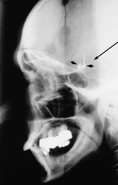
One clinical solution to these problems is to take two views, at right angles to one another (see Figs 1.9 and 1.10). Unfortunately, even two views may still not be able to provide all the desired information for a diagnosis to be made (see Fig. 1.11).
These limitations of the conventional radiographic image have very important clinical implications and may be the underlying reason for a negative radiographic report. The fact that a particular feature or condition is not visible on one radiograph does not mean that the feature or condition does not exist, merely that it cannot be seen. The recently developed advanced imaging modalities such as cone beam computed tomography (CBCT) and medical computed tomography (CT) have been designed to try to overcome some of these limitations (see Chs 16 and 18).
Quality of the radiographic image
• Contrast – the visual difference between the various black, white and grey shadows
• Image geometry – the relative positions of the image receptor, object and X-ray tubehead
These factors are in turn dependent on several variables, relating to the density of the object, the type of image receptor and the X-ray equipment. They are discussed in greater detail in Chapter 17. However, to introduce how the geometrical accuracy and detail of the final image can be influenced, two of the main factors are considered below.
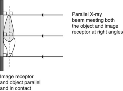
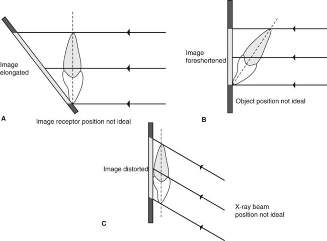
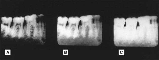
Positioning of the image receptor, object and X-ray beam
• The object and the image receptor should be in contact or as close together as possible
• The object and the image receptor should be parallel to one another
• The X-ray tubehead should be positioned so that the beam meets both the object and the image receptor at right angles.
These ideal requirements are shown diagrammatically in Fig. 1.12. The effects on the final image of varying the position of the object, image receptor or X-ray beam are shown in Fig. 1.13.
X-ray beam characteristics
The ideal X-ray beam used for imaging should be:
• Sufficiently penetrating, to pass through the patient and react with the film emulsion or digital sensor and produce good contrast between the different shadows (Fig. 1.14)
• Parallel, i.e. non-diverging, to prevent magnification of the image
• Produced from a point source, to reduce blurring of the edges of the image, a phenomenon known as the penumbra effect.
These ideal characteristics are discussed further in Chapter 3.
Perception of the radiographic image
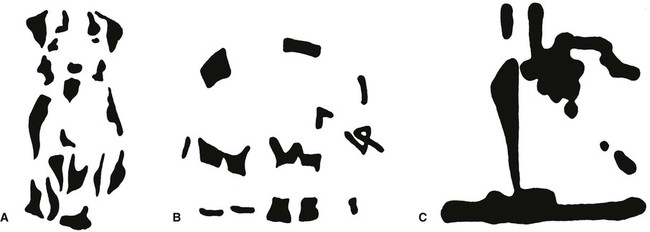
Effect of partial images
As mentioned already, the radiographic image only provides the clinician with a partial image with limited information in the form of different density shadows. To complete the picture, the clinician fills in the gaps, but we do not all necessarily do this in the same way and may arrive at different conclusions. Three non-clinical examples are shown in Fig. 1.15. Clinically, our differing perceptions may lead to different diagnoses.
Effect of contrast
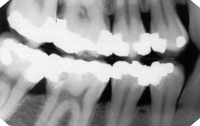
The apparent density of a particular radiographic shadow can be affected considerably by the density of the surrounding shadows. In other words, the contrast between adjacent structures can alter the perceived density of one or both of them (see Fig. 1.16). This is of particular importance in dentistry, where metallic restorations produce densely white radiopaque shadows that can affect the apparent density of the adjacent tooth tissue. This is discussed again in Chapter 20 in relation to caries diagnosis.

Effect of context
The environment or context in which we see an image can affect how we interpret that image. A non-clinical example is shown in Fig. 1.17. In dentistry, the environment that can affect our perception of radiographs is that created by the patient’s description of the complaint. We can imagine that we see certain radiographic changes, because the patient has conditioned our perceptual apparatus.
Common types of dental radiographs
The various radiographic images of the teeth, jaws and skull are divided into two main groups:
• Intraoral – the image receptor is placed inside the patient’s mouth, including:
• Extraoral – the image receptor is placed outside the patient’s mouth, including:
These various radiographic techniques are described later, in the chapters indicated. The approach and format adopted throughout these radiography chapters are intended to be straightforward, practical and clinically relevant and are based upon the essential knowledge required. This includes:
• WHY each particular projection is taken – i.e. the main clinical indications
• HOW the projections are taken – i.e. the relative positions of the patient, image receptor and X-ray tubehead
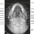
• WHAT the resultant radiographs should look like and which anatomical features they show.
To access the self assessment questions for this chapter please go to www.whaitesessentialsdentalradiography.com