[level-membership-for-radiology-category]
Skull and maxillofacial radiography
Radiographs of the whole head were traditionally required for a variety of purposes and because of the complexity of the structure of the maxillofacial skeleton a range of projections was devised. In some cases these techniques have been superseded by computed tomography (CT) (see Ch. 18) and cone beam computed tomography (CBCT) (see Ch. 16). However, this sophisticated CT equipment is not universally available. This chapter therefore provides a brief summary of the original main maxillofacial/skull projections, why and how each is taken, what the resultant radiograph looks like and which normal anatomical features are shown.
Equipment, patient positioning and projections
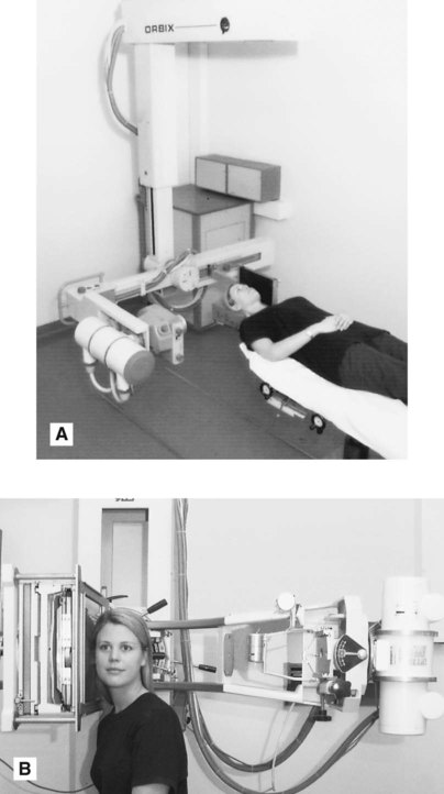
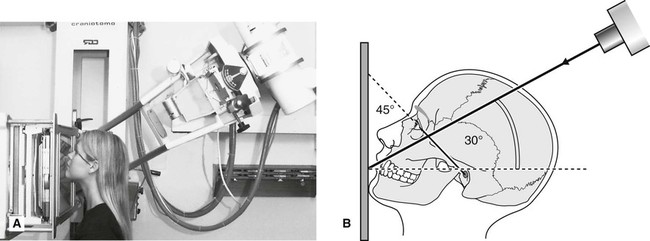
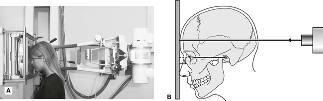
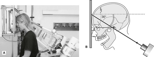
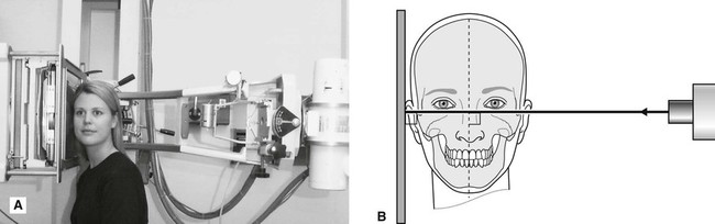
Most skull radiographs are taken using an isocentric skull unit such as the Orbix®, often with the patient lying down, or using a conventional skull unit such as the Craniotome® with the patient sitting up, as shown in Fig. 13.1.
The main maxillofacial/skull projections are:
• Standard occipitomental (0° OM)
• Posteroanterior of the skull (PA skull) or occipitofrontal (OF)
• Posteroanterior of the jaws (PA jaws)
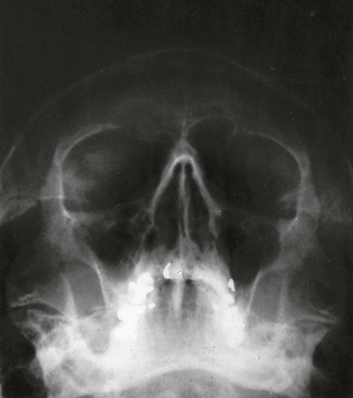
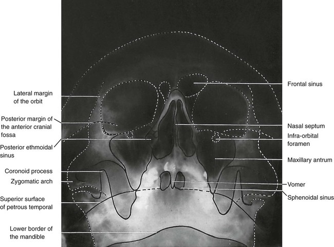
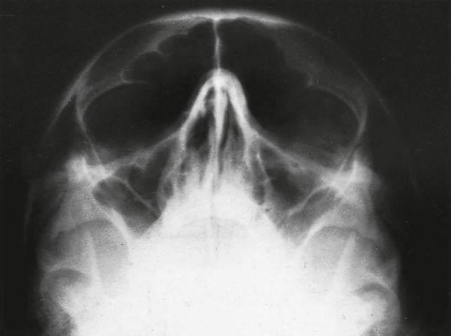
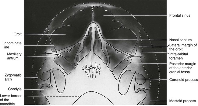
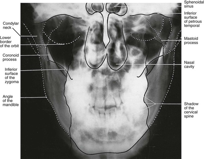
Standard occipitomental (0° OM)
Main indications
Technique and positioning
This can be summarized as follows:
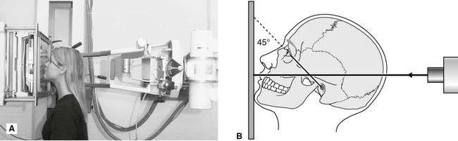
1. The patient is positioned facing the image receptor with the head tipped back so the radiographic baseline is at 45° to the image receptor, the so-called nose–chin position. This positioning drops the dense bones of the base of the skull downwards and raises the facial bones so they can be seen.
2. The X-ray tubehead is positioned with the central ray horizontal (0°) centred through the occiput (see Fig. 13.3B).
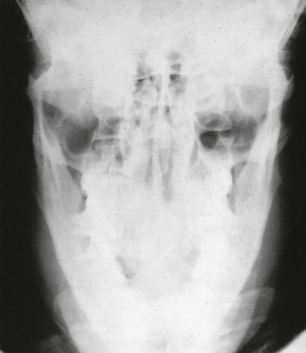
30° occipitomental (30° OM)
Main indications
The main clinical indications include:
Note: Ideally for fracture diagnosis two views at right angles are required (see Ch. 29), but the 0° OM and 30° OM provide two views of the facial bones at two different angles – therefore in cases of suspected facial fracture both views are needed.
Technique and positioning
This can be summarized as follows:
1. The patient is in exactly the same position as for the 0° OM, i.e. the head tipped back, radiographic baseline at 45° to the image receptor, in the nose–chin position.
2. The X-ray tubehead is aimed downwards from above the head, with the central ray at 30° to the horizontal, centred through the lower border of the orbit (see Fig. 13.6).
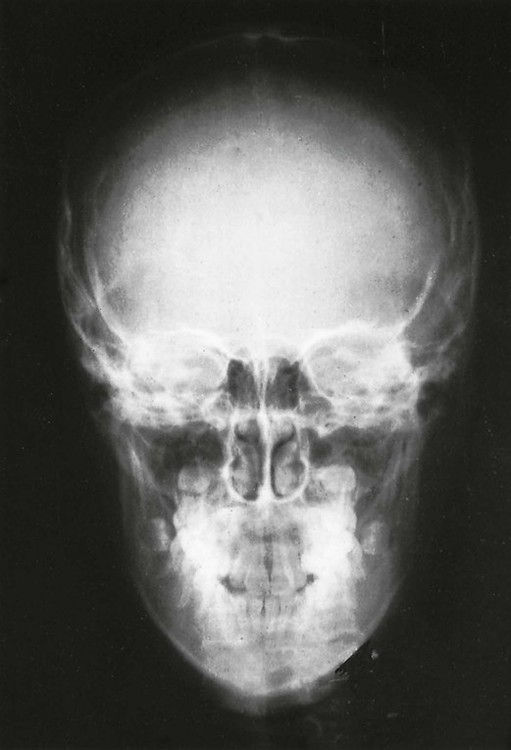
Posteroanterior of the skull (PA skull)
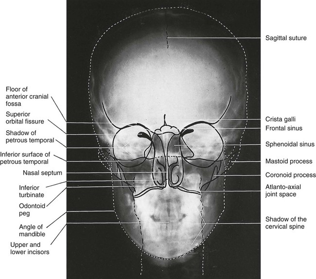
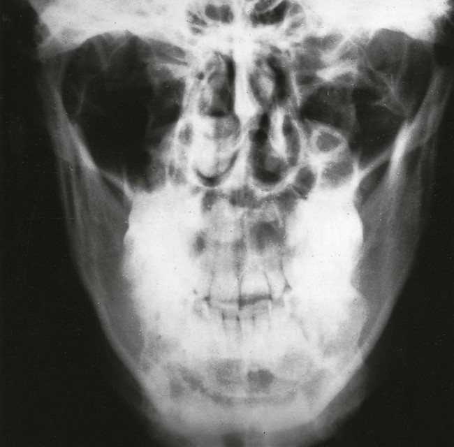
This projection shows the skull vault, primarily the frontal bones and the jaws.
Technique and positioning
This can be summarized as follows:
1. The patient is positioned facing the image receptor with the head tipped forwards so that the forehead and tip of the nose touch the image receptor – the so-called forehead–nose position. The radiographic baseline is horizontal and at right angles to the image receptor. This positioning levels off the base of the skull and allows the vault of the skull to be seen without superimposition.
2. The X-ray tubehead is positioned with the central ray horizontal (0°) centred through the occiput (see Fig. 13.9).
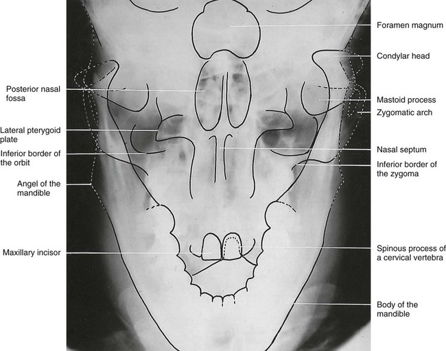
Posteroanterior of the jaws (PA jaws/PA mandible)
Technique and positioning
This can be summarized as follows:
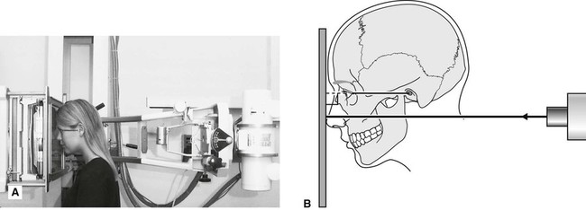
1. The patient is in exactly the same position as for the PA skull, i.e. the head tipped forward, the radiographic baseline horizontal and perpendicular to the image receptor in the forehead–nose position.
2. The X-ray tubehead is again horizontal (0°), but now the central ray is centred through the cervical spine at the level of the rami of the mandible (see Fig. 13.12).
Reverse Towne’s
Technique and positioning
This can be summarized as follows:
1. The patient is in the PA position, i.e. the head tipped forwards in the forehead–nose position, but in addition the mouth is open. The radiographic baseline is horizontal and at right angles to the image receptor. Opening the mouth takes the condylar heads out of the glenoid fossae so they can be seen.
2. The X-ray tubehead is aimed upwards from below the occiput, with the central ray at 30° to the horizontal, centred through the condyles (see Fig. 13.15).
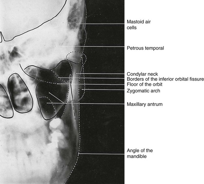
Rotated posteroanterior (rotated PA)
Technique and positioning
This can be summarized as follows:
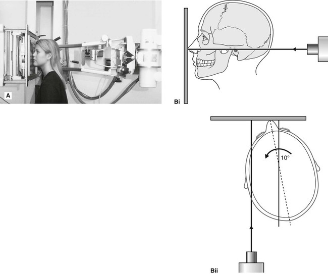
1. The patient is positioned facing the image receptor, with the occlusal plane horizontal and the tip of the nose touching the image receptor in the so-called normal head position.
2. The head is then rotated 10° to the side of interest. This positioning rotates the bones of the back of the skull away from the side of the face under investigation.
3. The X-ray tubehead is positioned with the central ray horizontal (0°), aimed down the side of the face (see Fig. 13.18).
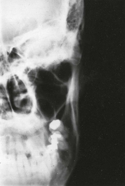
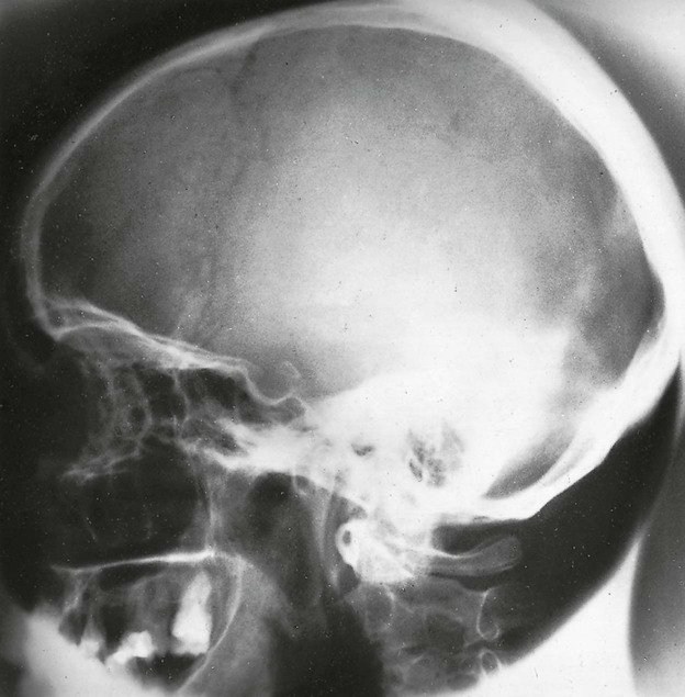
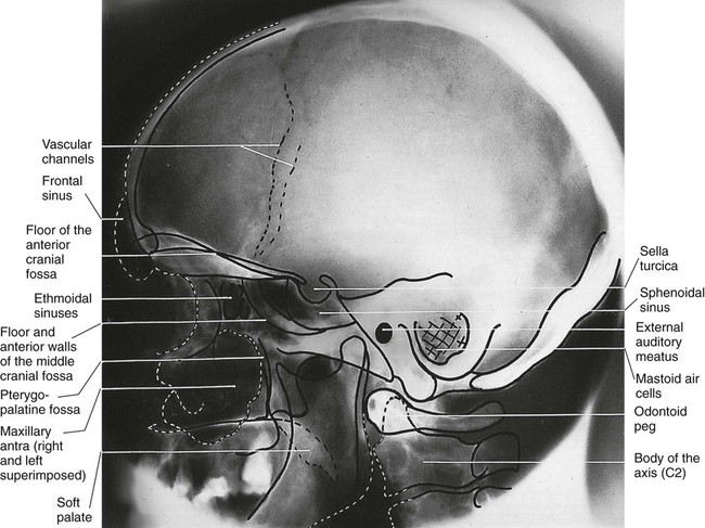
True lateral skull
This projection shows the skull vault and facial skeleton from the lateral aspect. The main difference between the true lateral skull and the true cephalometric lateral skull taken on the cephalostat (see Ch. 14) is that the true lateral skull is not standardized or reproducible. This view is used when a single lateral view of the skull is required but not in orthodontics or growth studies.
Main indications
Technique and positioning
This can be summarized as follows:
1. The patient is positioned with the head turned through 90°, so the side of the face touches the image receptor. In this position, the sagittal plane of the head is parallel to the image receptor.
2. The X-ray tubehead is positioned with the central ray horizontal (0°) and perpendicular to the sagittal plane and the image receptor, centred through the external auditory meatus (see Fig. 13.21).
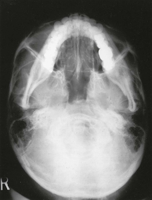
Submentovertex (SMV)
This projection shows the base of the skull, sphenoidal sinuses and facial skeleton from below.
Technique and positioning
This can be summarized as follows:
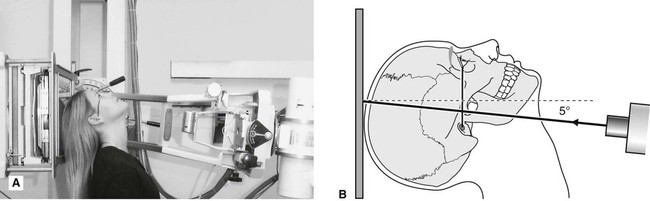
1. The patient is positioned facing away from the image receptor. The head is tipped backwards as far as is possible, so the vertex of the skull touches the image receptor. In this position, the radiographic baseline is vertical and parallel to the image receptor.
2. The X-ray tubehead is aimed upwards from below the chin, with the central ray at 5° to the horizontal, centred on an imaginary line joining the lower first molars (see Fig. 13.24).
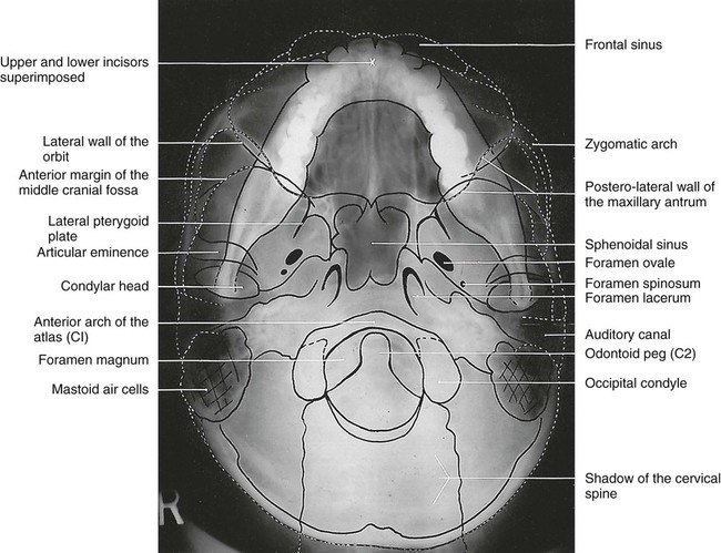
Note: The head positioning required for this projection means it is contraindicated in patients with suspected neck injuries, especially suspected fracture of the odontoid peg.
To access the self assessment questions for this chapter please go to www.whaitesessentialsdentalradiography.com
[/level-membership-for-radiology-category][not-level-membership-for-radiology-category]
Skull and maxillofacial radiography
Radiographs of the whole head were traditionally required for a variety of purposes and because of the complexity of the structure of the maxillofacial skeleton a range of projections was devised. In some cases these techniques have been superseded by computed tomography (CT) (see Ch. 18) and cone beam computed tomography (CBCT) (see Ch. 16). However, this sophisticated CT equipment is not universally available. This chapter therefore provides a brief summary of the original main maxillofacial/skull projections, why and how each is taken, what the resultant radiograph looks like and which normal anatomical features are shown.
Equipment, patient positioning and projections
Most skull radiographs are taken using an isocentric skull unit such as the Orbix®, often with the patient lying down, or using a conventional skull unit such as the Craniotome® with the patient sitting up, as shown in Fig. 13.1.
The main maxillofacial/skull projections are:
• Standard occipitomental (0° OM)
• Posteroanterior of the skull (PA skull) or occipitofrontal (OF)
• Posteroanterior of the jaws (PA jaws)
Standard occipitomental (0° OM)
Main indications
Technique and positioning
This can be summarized as follows:
1. The patient is positioned facing the image receptor with the head tipped back so the radiographic baseline is at 45° to the image receptor, the so-called nose–chin position. This positioning drops the dense bones of the base of the skull downwards and raises the facial bones so they can be seen.
2. The X-ray tubehead is positioned with the central ray horizontal (0°) centred through the occiput (see Fig. 13.3B).
30° occipitomental (30° OM)
Main indications
The main clinical indications include:
Note: Ideally for fracture diagnosis two views at right angles are required (see Ch. 29), but the 0° OM and 30° OM provide two views of the facial bones at two different angles – therefore in cases of suspected facial fracture both views are needed.
Technique and positioning
This can be summarized as follows:
1. The patient is in exactly the same position as for the 0° OM, i.e. the head tipped back, radiographic baseline at 45° to the image receptor, in the nose–chin position.
2. The X-ray tubehead is aimed downwards from above the head, with the central ray at 30° to the horizontal, centred through the lower border of the orbit (see Fig. 13.6).
[/not-level-membership-for-radiology-category]
