1
The Body
How can gross anatomy be studied?
Functional subdivisions of the CNS
 Image Library—illustrations from
What is anatomy?
Anatomy includes those structures that can be seen grossly (without the aid of magnification) and microscopically (with the aid of magnification). Typically, when used by itself, the term anatomy tends to mean gross or macroscopic anatomy—that is, the study of structures that can be seen without using a microscopic. Microscopic anatomy, also called histology, is the study of cells and tissues using a microscope.
Observation and visualization are the primary techniques a student should use to learn anatomy. Anatomy is much more than just memorization of lists of names. Although the language of anatomy is important, the network of information needed to visualize the position of physical structures in a patient goes far beyond simple memorization. Knowing the names of the various branches of the external carotid artery is not the same as being able to visualize the course of the lingual artery from its origin in the neck to its termination in the tongue. An understanding of anatomy requires an understanding of the context in which the terminology can be remembered.
HOW CAN GROSS ANATOMY BE STUDIED?
The term anatomy is derived from the Greek word temnein, meaning “to cut.” Clearly, at its root, the study of anatomy is linked to dissection. Dissection of cadavers by students is now augmented, or even in some cases replaced, by viewing prosected (previously dissected) material and plastic models, or using computer teaching modules and other learning aids.
Anatomy can be studied following either a regional or a systemic approach.
 With a regional approach, each region of the body is studied separately and all aspects of that region are studied at the same time. For example, if the thorax is to be studied, all of its structures are examined. This includes the vasculature, nerves, bones, muscles, and all other structures and organs located in the region of the body defined as the thorax. After studying this region, the other regions of the body (i.e., the abdomen, pelvis, lower limb, upper limb, back, head, and neck) are studied in a similar fashion.
 In contrast, in a systemic approach, each system of the body is studied and followed throughout the entire body. For example, a study of the cardiovascular system looks at the heart and all of the blood vessels in the body. This approach continues for the whole body until every system, including the nervous, skeletal, muscular, gastrointestinal, respiratory, lymphatic, and reproductive systems, has been studied.
IMPORTANT ANATOMICAL TERMS
The anatomical position
The anatomical position is the standard reference position of the body used to describe the location of structures (Fig. 1.1). The body is in the anatomical position when standing upright with feet together, hands by the side, and face looking forward. The mouth is closed and the facial expression is neutral. The rim of bone under the eyes is in the same horizontal plane as the top of the opening to the ear, and the eyes are open and focused on something in the distance. The palms of the hands face forward with the fingers straight and together and with the pad of the thumb turned 90° to the pads of the fingers. The toes point forward.
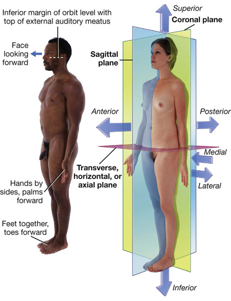
Fig. 1.1 The anatomical position, planes, and terms of location and orientation.
Anatomical planes
Three major groups of planes pass through the body in the anatomical position (Fig. 1.1).
 Coronal planes are oriented vertically and divide the body into anterior and posterior parts.
 Sagittal planes also are oriented vertically, but are at right angles to the coronal planes and divide the body into right and left parts. The plane that passes through the center of the body dividing it into equal right and left halves is termed the median sagittal plane.
 Transverse, horizontal, or axial planes divide the body into superior and inferior parts.
Terms to describe location
Anterior (ventral) and posterior (dorsal), medial and lateral, superior and inferior
Three major pairs of terms are used to describe the location of structures relative to the body as a whole or to other structures (Fig. 1.1).
 Anterior (or ventral) and posterior (or dorsal) describe the position of structures relative to the “front” and “back” of the body. For example, the nose is an anterior (ventral) structure, whereas the vertebral column is a posterior (dorsal) structure.
 Medial and lateral describe the position of structures relative to the median sagittal plane and the sides of the body. For example, the thumb is lateral to the little finger.
 Superior and inferior describe structures in reference to the vertical axis of the body. For example, the head is superior to the shoulders.
Proximal and distal, cranial and caudal, and rostral
Other terms used to describe positions include proximal and distal, cranial and caudal, and rostral.
 Proximal and distal are used with reference to being closer to or farther from a structure’s origin, particularly in the limbs. For example, the hand is distal to the elbow joint. These terms are also used to describe the relative positions of branches along the course of linear structures, such as airways, vessels, and nerves. For example, distal branches occur farther away toward the ends, whereas proximal branches occur closer to and toward the origin.
 Cranial (toward the head) and caudal (toward the tail) are sometimes used instead of superior and inferior, respectively.
 Rostral is used, particularly in the head, to describe the position of a structure with reference to the nose. For example, the forebrain is rostral to the hindbrain.
Superficial and deep
Two other terms used to describe the position of structures in the body are superficial and deep. These terms are used to describe the relative positions of two structures with respect to the surface of the body. For example, the sternum is superficial to the heart.
Imaging
DIAGNOSTIC IMAGING TECHNIQUES
In 1895 Wilhelm Röntgen used the X-rays from a cathode ray tube to expose a photographic plate and produce the first radiographic exposure of his wife’s hand. Over the past 30 years there has been a revolution in medical imaging, which has been paralleled by developments in computer technology.
Plain radiography
The basic physics of X-ray generation has not changed.
X-rays are photons (a type of electromagnetic radiation) and are generated from a complex X-ray tube, which is a type of cathode ray tube (Fig. 1.2). The X-rays are then collimated (i.e., directed through lead-lined shutters to stop them from fanning out) to the appropriate area, as determined by the radiographic technician. As the X-rays pass through the body they are attenuated (reduced in energy) by the tissues. Those X-rays that pass through the tissues interact with the photographic film.
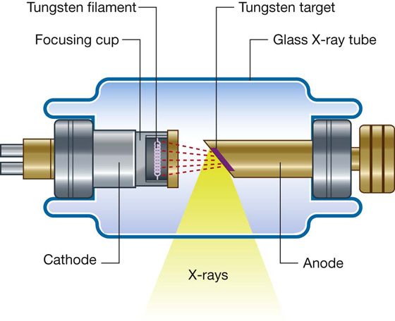
Fig. 1.2 Cathode ray tube for the production of X-rays.
In the body:
 Air attenuates X-rays a little.
 Fat attenuates X-rays more than air but less than water.
 Bone attenuates X-rays the most.
These differences in attenuation result in differences in the level of exposure of the film. When the photographic film is developed, bone appears white on the film because this region of the film has been exposed to the least amount of X-rays. Air appears dark on the film because these regions were exposed to the greatest number of X-rays. Modifications to this X-ray technique allow a continuous stream of X-rays to be produced from the X-ray tube and collected on an input screen to allow real-time visualization of moving anatomical structures, barium studies, angiography, and fluoroscopy (Fig. 1.3).
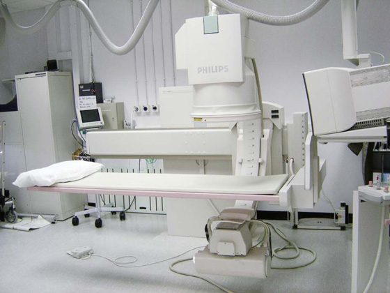
Fig. 1.3 Fluoroscopy unit.
Contrast agents
To demonstrate specific structures, such as bowel loops or arteries, it may be necessary to fill these structures with a substance that attenuates X-rays more than bowel loops or arteries do normally. It is, however, extremely important that these substances are nontoxic. Barium sulfate, an insoluble salt, is a nontoxic, relatively high-density agent that is extremely useful in the examination of the gastrointestinal tract. When barium sulfate suspension is ingested it attenuates X-rays and can therefore be used to demonstrate the bowel lumen (Fig. 1.4).
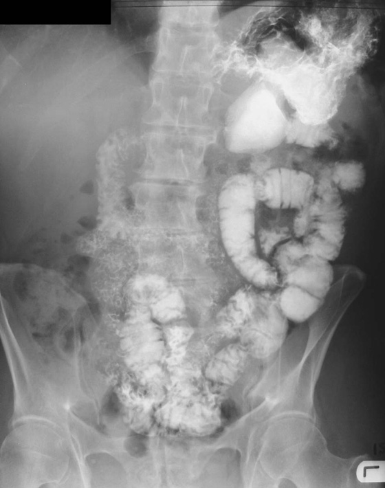
Fig. 1.4 Barium sulfate follow-through.
For some patients it is necessary to inject contrast agents directly into arteries or veins. In this case, iodine-based molecules are suitable contrast agents. Iodine is chosen because it has a relatively high atomic mass and so markedly attenuates X-rays, but also, importantly, it is naturally excreted via the urinary system. Intra-arterial and intravenous contrast agents are extremely safe and are well tolerated by most patients. These agents not only help in visualizing the arteries and veins, but because they are excreted by the urinary system, can also be used to visualize the kidneys, ureter, and bladder in a process known as intravenous urography.
Subtraction angiography
During angiography it is often difficult to appreciate the contrast agent in the vessels through the overlying bony structures. To circumvent this, the technique of subtraction angiography has been developed. Simply, one or two images are obtained before the injection of contrast media. These images are inverted (such that a negative is created from the positive image). After injection of the contrast media into the vessels, a further series of images are obtained, demonstrating the passage of the contrast through the arteries and into the veins. By adding the “negative precontrast image” to the positive postcontrast images, the bones and soft tissues are subtracted to produce a solitary image of contrast only (Fig. 1.5).
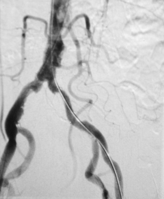
Fig. 1.5 Digital subtraction angiogram.
Ultrasound
Ultrasonography of the body is widely used for all aspects of medicine (Fig. 1.6).
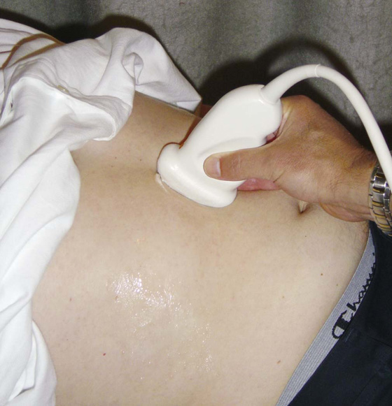
Fig. 1.6 Ultrasound examination of the abdomen.
Ultrasound is a very high frequency sound wave (not electromagnetic radiation) generated by piezoelectric materials, such that a series of sound waves is produced. Importantly, the piezoelectric material can also receive the sound waves that bounce back from the internal organs. The sound waves are then interpreted by a powerful computer, and a real-time image is produced on the display panel.
Doppler ultrasound
Developments in ultrasound technology, including the size of the probes and the frequency range, mean that a broad range of areas can now be scanned.
Traditionally ultrasound is used for assessing the abdomen (Fig. 1.6) and the fetus in pregnant women. Ultrasound is also widely used to assess the eyes, neck, soft tissues, and peripheral musculoskeletal system. Probes have been placed on endoscopes, and endoluminal ultrasound of the esophagus, stomach, and duodenum is now routine. Endocavity ultrasound is carried out most commonly to assess the genital tract in women using a transvaginal or transrectal route. In men, transrectal ultrasound is the imaging method of choice to assess the prostate in those with suspected prostate hypertrophy or malignancy.
Doppler ultrasound enables determination of flow, its direction, and its velocity within a vessel using simple ultrasound techniques. Sound waves bounce off moving structures and are returned. The degree of frequency shift determines whether the object is moving away from or toward the probe and the speed at which it is traveling.
Computed tomography
Computed tomography (CT) was invented in the 1970s by Sir Godfrey Hounsfield, who was awarded the Nobel Prize in Medicine in 1979. Since this inspired invention, there have been many generations of CT scanners.
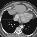
A CT scanner obtains a series of images of the body (slices) in the axial plane. The patient lies on a bed, an X-ray tube passes around the body (Fig. 1.7), and a series of images are obtained. A computer carries out a complex mathematical transformation on the multitude of images to produce the final image (Fig. 1.8).
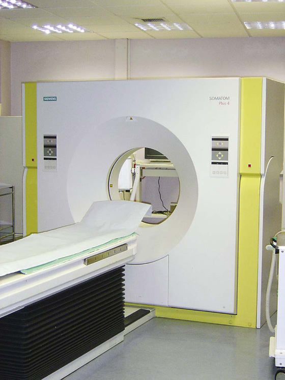
Fig. 1.7 Computed tomography scanner.
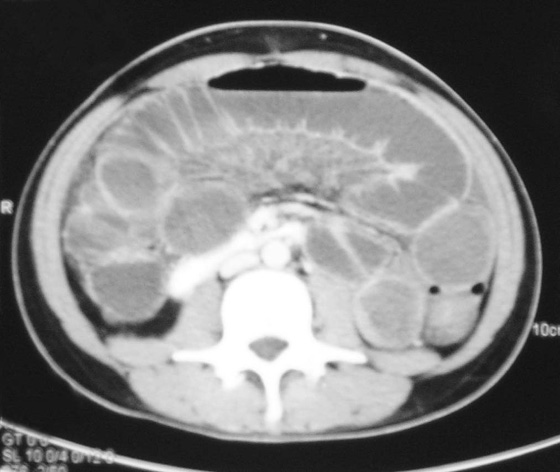
Fig. 1.8 Computed tomography scan of the abdomen at vertebral level L2.
Magnetic resonance imaging
The process of magnetic resonance imaging (MRI) is dependent on the free protons in the hydrogen nuclei in molecules of water (H2O). Because water is present in almost all biological tissues, the hydrogen proton is ideal. The protons within a patient’s hydrogen nuclei should be regarded as small bar magnets, which are randomly oriented in space. The patient is placed in a strong magnetic field, which aligns the bar magnets. When a pulse of radio waves is passed through the patient the magnets are deflected, and as they return to their aligned position they emit small radio pulses. The strength and frequency of the emitted pulses and the time it takes for the protons to return to their pre-excited state produces a signal. These signals are analyzed by a powerful computer, and an image is created (Fig. 1.9).
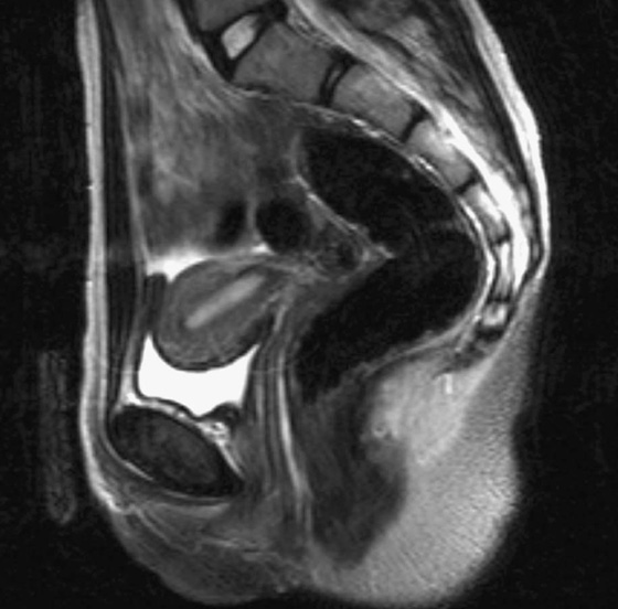
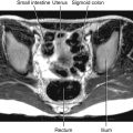
Fig. 1.9 A T2-weighted image in the sagittal plane of the pelvic viscera in a woman.
By altering the sequence of pulses to which the protons are subjected, different properties of the protons can be assessed. These properties are referred to as the “weighting” of the scan. By altering the pulse sequence and the scanning parameters, T1-weighted images (Fig. 1.10A) and T2-weighted images (Fig. 1.10B) can be obtained. These two types of imaging sequences provide differences in image contrast, which accentuate and optimize different tissue characteristics.
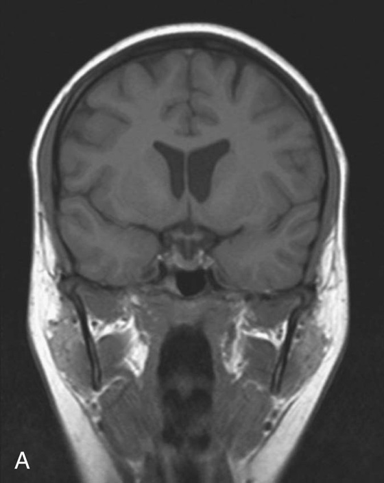
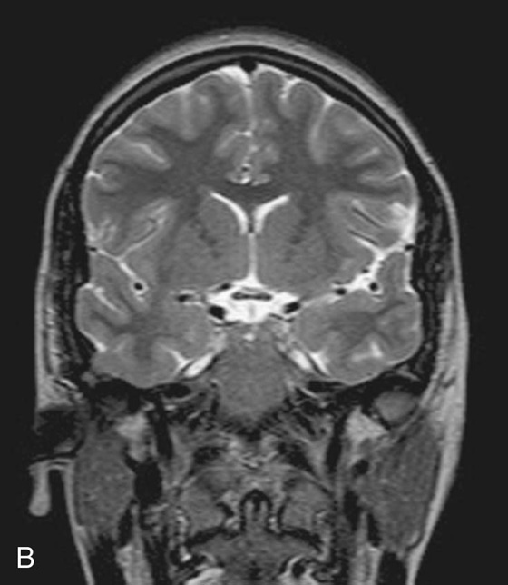
Fig. 1.10 T1-weighted (A) and T2-weighted (B) magnetic resonance images of the brain in the coronal plane.
From the clinical point of view:
 Most T1-weighted images show dark fluid and bright fat—for example, within the brain the cerebrospinal fluid (CSF) is dark.
 T2-weighted images demonstrate a bright signal from fluid and an intermediate signal from fat—for example, in the brain the CSF appears white.
MRI can also be used to assess flow within vessels and to produce complex angiograms of the peripheral and cerebral circulation.
Nuclear medicine imaging
Nuclear medicine involves imaging using gamma rays, which are another type of electromagnetic radiation. The important difference between gamma rays and X-rays is that gamma rays are produced from within the nucleus of an atom when an unstable nucleus decays, whereas X-rays are produced by bombarding an atom with electrons.
For an area to be visualized, the patient must receive a gamma-ray emitter, which must have a number of properties to be useful, including a reasonable half-life (e.g., 6 to 24 hours); an easily measurable gamma ray; and an energy deposition in as low a dose as possible in the patient’s tissues.
The most commonly used radionuclide (radioisotope) is technetium-99m. This may be injected as a technetium salt or combined with other complex molecules. For example, by combining technetium-99m with methylene diphosphonate (MDP), a radiopharmaceutical is produced. When injected into the body this radiopharmaceutical specifically binds to bone, allowing assessment of the skeleton. Similarly, combining technetium-99m with other compounds permits assessment of other parts of the body; for example, the urinary tract and cerebral blood flow.
Images obtained using a gamma camera are dependent on how the radiopharmaceutical is absorbed, distributed, metabolized, and excreted by the body after injection.
Positron emission tomography
Positron emission tomography (PET) is an imaging modality for detecting positron-emitting radionuclides. A positron is an antielectron, which is a positively charged particle of antimatter. Positrons are emitted from the decay of proton-rich radionuclides. Most of these radionuclides are made in a cyclotron and have extremely short half-lives.
The most commonly used PET radionuclide is fluorodeoxyglucose (FDG) labeled with fluorine-18 (a positron emitter). Tissues that are actively metabolizing glucose take up this compound, and the resulting localized high concentration of this molecule compared to background emission is detected as a “hot spot.”
PET has become an important imaging modality in the detection of cancer and the assessment of its treatment and recurrence.
IMAGE INTERPRETATION
Plain radiography
Plain radiographs are undoubtedly the most common form of image obtained in a hospital or local practice. Before interpretation, it is important to know about the imaging technique and the standard views obtained.
In most instances (apart from chest radiography), the X-ray tube is 1 m away from the X-ray film. The object in question, for example a hand or a foot, is placed upon the film. When describing subject placement for radiography, the part closest to the X-ray tube is referred to as “anterior” and that closest to the film is referred to as “posterior.”
When X-rays are viewed on a viewing box, the right side of the patient is placed to the observer’s left; therefore, the observer views the radiograph as though looking at a patient in the anatomical position.
Chest radiograph
The chest radiograph is one of the most commonly requested plain radiographs. An image is taken with the patient erect and placed posteroanteriorly (PA chest radiograph).
Occasionally, when patients are too unwell to stand erect, films are obtained on the bed in an anteroposterior (AP) position. These films are less standardized than PA films, and caution should always be taken when interpreting AP radiographs.
A good quality chest radiograph will demonstrate the lungs, cardiomediastinal contour, diaphragm, ribs, and peripheral soft tissues.
Abdominal radiograph
Plain abdominal radiographs are obtained in the AP supine position. From time to time an erect plain abdominal radiograph is obtained when small bowel obstruction is suspected.
Gastrointestinal contrast examinations
High-density contrast medium is ingested to opacify the esophagus, stomach, small bowel, and large bowel. The bowel is insufflated with air (or carbon dioxide) to provide a double-contrast study. In many countries, endoscopy has superseded upper gastrointestinal imaging, but the mainstay for imaging the large bowel is the double-contrast barium enema. Typically the patient needs to undergo bowel preparation, in which powerful cathartics are used to empty the bowel. At the time of the examination a small tube is placed into the rectum and a barium suspension is run into the large bowel. The patient undergoes a series of twists and turns so that the contrast passes through the entire large bowel. The contrast is emptied and air is passed through the same tube to insufflate the large bowel. A thin layer of barium coats the normal mucosa, allowing mucosal detail to be visualized (see Fig. 1.4).
Urological contrast studies
Intravenous urography is the standard investigation for assessing the urinary tract. Intravenous contrast medium is injected, and images are obtained as the medium is excreted through the kidneys. A series of films are obtained during this period from immediately after the injection up to approximately 20 minutes later, when the bladder is full of contrast medium.
This series of radiographs demonstrates the kidneys, ureters, and bladder and enables assessment of the retroperitoneum and other structures that may press on the urinary tract.
Computed tomography
Computed tomography is the preferred terminology rather than computerized tomography, though physicians use both terms interchangeably.
Most images are acquired in the axial plane and viewed such that the observer looks from below and upward toward the head (from the foot of the bed). By implication:
 the right side of the patient is on the left side of the image; and
 the uppermost border of the image is anterior.
Many patients are given oral and intravenous contrast media to differentiate bowel loops from other abdominal organs and to assess the vascularity of normal anatomical structures. When intravenous contrast is given, the earlier the images are obtained, the greater the likelihood of arterial enhancement. As the time is delayed between injection and image acquisition, a venous phase and an equilibrium phase are also obtained.
The great advantage of CT scanning is the ability to extend and compress the gray scale to visualize the bones, soft tissues, and visceral organs. Altering the window settings and window centering provides the physician with specific information about these structures.
Magnetic resonance imaging
There is no doubt that MRI has revolutionized the understanding and interpretation of the brain and its coverings (Fig. 1.10). Furthermore, it has significantly altered the practice of musculoskeletal medicine and surgery. Images can be obtained in any plane and in most sequences. Typically the images are viewed using the same principles as computed tomography. Intravenous contrast agents are also used to further enhance tissue contrast. Typically, MRI contrast agents contain paramagnetic substances (e.g., gadolinium and manganese).
Nuclear medicine imaging
Most nuclear medicine images are functional studies. Images are usually interpreted directly from a computer, and a series of representative films are obtained for clinical use.
SAFETY IN IMAGING
Whenever a patient undergoes an X-ray or nuclear medicine investigation, a dose of radiation is given (Table 1.1). As a general principle, it is expected that the dose given is as low as reasonably possible for a diagnostic image to be obtained. Numerous laws govern the amount of radiation exposure that a patient can undergo for a variety of procedures, and these are monitored to prevent any excess or additional dosage.
Table 1.1 The approximate dosage of radiation exposure as an order of magnitude
|
Examination |
Typical effective dose (mSv) |
Equivalent duration of background exposure |
|
Chest radiograph |
0.02 |
3 days |
|
Abdomen |
1.00 |
6 months |
|
Intravenous urography |
2.50 |
14 months |
|
CT scan of head |
2.30 |
1 year |
|
CT scan of abdomen and pelvis |
10.00 |
4.5 years |
Imaging modalities such as ultrasound and MRI are ideal because they do not impart significant risk to the patient. Moreover, ultrasound imaging is the modality of choice for assessing the fetus.
Body systems
SKELETAL SYSTEM
The skeleton can be divided into two subgroups, the axial skeleton and the appendicular skeleton. The axial skeleton consists of the bones of the skull (cranium), vertebral column, ribs, and sternum, whereas the appendicular skeleton consists of the bones of the upper and lower limbs (Fig. 1.11).
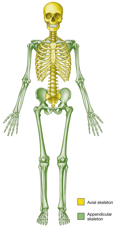
Fig. 1.11 The axial skeleton and the appendicular skeleton.
The skeletal system consists of cartilage and bone.
Cartilage
Cartilage is an avascular form of connective tissue consisting of extracellular fibers embedded in a matrix that contains cells localized in small cavities. The amount and kind of extracellular fibers in the matrix vary depending on the type of cartilage. In heavy weightbearing areas or areas prone to pulling forces, the amount of collagen is greatly increased and the cartilage is almost inextensible. In contrast, in areas where weightbearing demands and stress are less, cartilage containing elastic fibers and fewer collagen fibers are common. The functions of cartilage are to:
 support soft tissues,
 provide a smooth, gliding surface for bone articulations at joints, and
 enable the development and growth of long bones.
There are three types of cartilage:
 hyaline—most common; matrix contains a moderate amount of collagen fibers (e.g., articular surfaces of bones);
 elastic—matrix contains collagen fibers along with a large number of elastic fibers (e.g., external ear);
 fibrocartilage—matrix contains a limited number of cells and ground substance amidst a substantial amount of collagen fibers (e.g., intervertebral discs).
Cartilage is nourished by diffusion and has no blood vessels, lymphatics, or nerves.
Bone
Bone is a calcified, living, connective tissue that forms the majority of the skeleton. It consists of an intercellular calcified matrix, which also contains collagen fibers, and several types of cells within the matrix. Bones function as:
 supportive structures for the body,
 protectors of vital organs,
 reservoirs of calcium and phosphorus,
 levers on which muscles act to produce movement, and
 containers for blood-producing cells.
There are two types of bone, compact and spongy (trabecular or cancellous). Compact bone is dense bone that forms the outer shell of all bones and surrounds spongy bone. Spongy bone consists of spicules of bone enclosing cavities containing blood-forming cells (marrow). Classification of bones is by shape.
 Long bones are tubular (e.g., humerus in the upper limb; femur in the lower limb).
 Short bones are cuboidal (e.g., bones of the wrist and ankle).
 Flat bones consist of two compact bone plates separated by spongy bone (e.g., skull).
 Irregular bones are bones with various shapes (e.g., bones of the face).
 Sesamoid bones are round or oval bones that develop in tendons.
Bones are vascular and are innervated. Generally, an adjacent artery gives off a nutrient artery, usually one per bone, which directly enters the internal cavity of the bone and supplies the marrow, spongy bone, and inner layers of compact bone. In addition, all bones are covered externally, except in the area of a joint where articular cartilage is present, by a fibrous connective tissue membrane called the periosteum, which has the unique capability of forming new bone. This membrane receives blood vessels whose branches supply the outer layers of compact bone. A bone stripped of its periosteum will not survive. Nerves accompany the vessels that supply the bone and the periosteum. Most of the nerves passing into the internal cavity with the nutrient artery are vasomotor fibers that regulate blood flow. Bone itself has few sensory nerve fibers. On the other hand, the periosteum is supplied with numerous sensory nerve fibers and is very sensitive to any type of injury.
Developmentally, all bones come from mesenchyme by either intramembranous ossification, in which mesenchymal models of bones undergo ossification, or endochondral ossification, in which cartilaginous models of bones form from mesenchyme and undergo ossification.
Imaging app
Determination of skeletal age
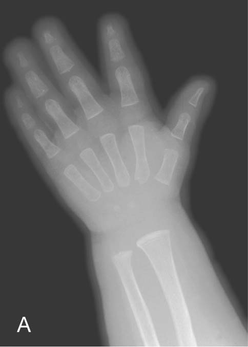
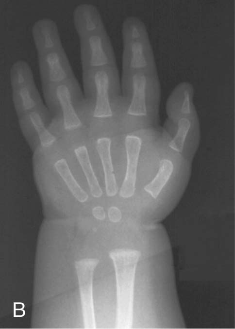
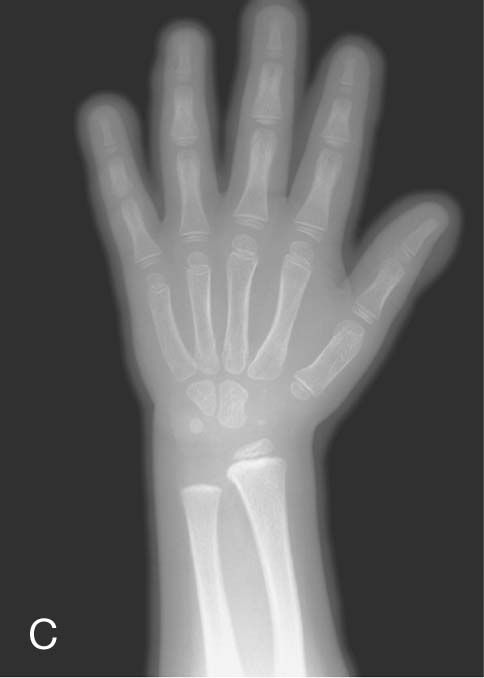
Throughout life the bones develop in a predictable way to form the skeletally mature adult at the end of puberty. In western countries, skeletal maturity tends to occur between the ages of 20 and 25 years.
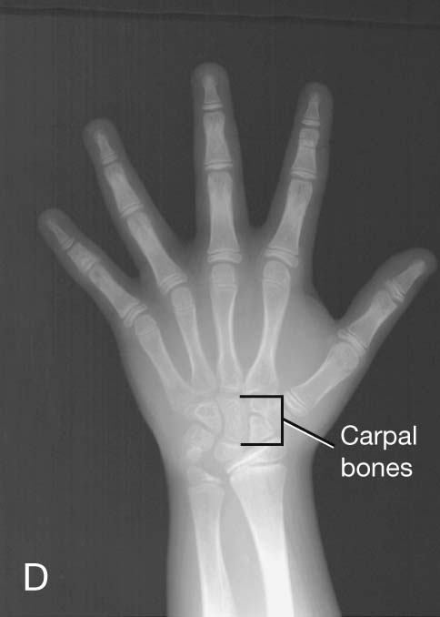
Up until the age of skeletal maturity, bony growth and development follow a typically predictable ordered state, which can be measured through either ultrasound, plain radiographs, or MRI scanning. Typically, the nondominant (left hand) is radiographed and is compared with a series of standard radiographs. From these images the bone age can be determined (Fig. 1.12).
Clinical app
Bone marrow transplants
There are two types of bone marrow, the red marrow (otherwise known as myeloid tissue) and the yellow marrow. Red blood cells, platelets, and most white blood cells arise from within the red marrow. In the yellow marrow a few white cells are made; however, this marrow is dominated by large fat globules (producing its yellow appearance).
From birth most of the body’s marrow is red; however, as the subject ages, more red marrow is converted into yellow marrow within the medulla of the long and flat bones.
There are a number of diseases that may involve the bone marrow, including infection and malignancy. In patients who develop a bone marrow malignancy (e.g., leukemia), it may be possible to harvest nonmalignant cells from the patient’s bone marrow or cells from another person’s bone marrow. The patient’s own marrow can be destroyed with chemotherapy or radiation and the new cells infused. This treatment is referred to as a bone marrow transplant.
Bone fractures
Fractures occur in normal bone because of abnormal load or stress, in which the bone gives way. Fractures may also occur in bone that is of poor quality (osteoporosis). In these cases, a normal stress is placed upon a bone that is not of sufficient quality to withstand this force and subsequently fractures.
In children whose bones are still developing, fractures may occur across the growth plate or across the shaft. These shaft fractures typically involve partial cortical disruption, similar to breaking a branch of a young tree; hence they are termed “greenstick” fractures.
Clinical app
Avascular necrosis
Avascular necrosis is cellular death of bone resulting from a temporary or permanent loss of blood supply to that bone. A typical site for avascular necrosis is a fracture across the femoral neck in an elderly patient. In these patients there is loss of continuity of the cortical medullary blood flow with loss of blood flow deep to the retinacular fibers. This essentially renders the femoral head bloodless; it subsequently undergoes necrosis and collapses. In these patients it is necessary to replace the femoral head with a prosthesis.
Clinical app
Osteoporosis
Osteoporosis is a disease in which the bone mineral density is significantly reduced. This renders the bone significantly more at risk of fracture. Typically, osteoporotic fractures occur in the femoral necks, the vertebra, and the wrist. Although osteoporosis may occur in men, especially elderly men, the typical patients are postmenopausal women.
Clinical app
Epiphyseal fractures
As the skeleton develops, there are stages of intense growth typically around the ages of 7 to 10 years and later in puberty. These growth spurts are associated with increased cellular activity around the growth plate and the metaphyseal region. This increase in activity renders the growth plates and metaphyseal regions more vulnerable to injuries such as dislocation across a growth plate or fracture through a growth plate. Occasionally an injury may result in growth plate compression, destroying that region of the growth plate, which may result in asymmetric growth.
Joints
The sites where two skeletal elements come together are termed joints. The two general categories of joints (Fig. 1.13) are those in which:
 the skeletal elements are separated by a cavity (i.e., synovial joints); and
 there is no cavity and the components are held together by connective tissue (i.e., solid joints).
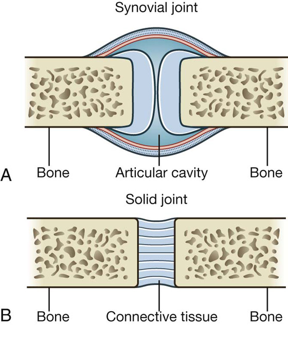
Fig. 1.13 Joints. A. Synovial joint. B. Solid joint.
Blood vessels that cross a joint and nerves that innervate muscles acting on a joint usually contribute articular branches to that joint.
Synovial joints
Synovial joints are connections between skeletal components where the elements involved are separated by a narrow articular cavity. In addition to containing an articular cavity, these joints have a number of characteristic features (Fig. 1.14).
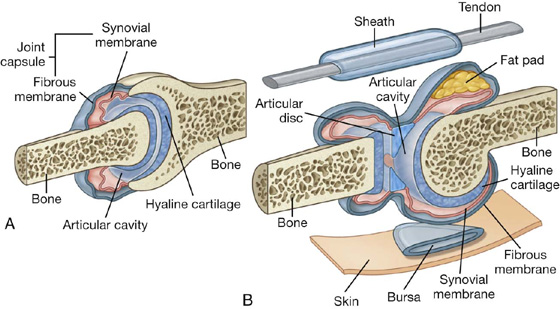
First, a layer of cartilage, usually hyaline cartilage, covers the articulating surfaces of the skeletal elements. In other words, bony surfaces do not normally contact one another directly. As a consequence, when these joints are viewed in normal radiographs, a wide gap seems to separate the adjacent bones because the cartilage that covers the articulating surfaces is more transparent to X-rays than bone.
A second characteristic feature of synovial joints is the presence of a joint capsule consisting of an inner synovial membrane and an outer fibrous membrane.
 The synovial membrane attaches to the margins of the joint surfaces at the interface between the cartilage and bone and encloses the articular cavity. The synovial membrane is highly vascular and produces synovial fluid, which percolates into the articular cavity and lubricates the articulating surfaces. Closed sacs of synovial membrane also occur outside joints where they form synovial bursae or tendon sheaths. Bursae often intervene between structures, such as tendons and bone, tendons and joints, or skin and bone, and reduce the friction of one structure moving over the other. Tendon sheaths surround tendons and also reduce friction.
 The fibrous membrane is formed by dense connective tissue and surrounds and stabilizes the joint. Parts of the fibrous membrane may thicken to form ligaments, which further stabilize the joint. Ligaments outside the capsule usually provide additional reinforcement.
Another common but not universal feature of synovial joints is the presence of additional structures within the area enclosed by the capsule or synovial membrane:
 Articular discs (usually composed of fibrocartilage) absorb compression forces, adjust to changes in the contours of joint surfaces during movements, and increase the range of movements that can occur at joints.
 Fat pads occur between the synovial membrane and the capsule and move into and out of regions as joint contours change during movement;
 tendons.
Descriptions of synovial joints based on shape and movement
Synovial joints are described based on shape and movement:
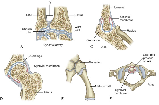
 Based on the shape of their articular surfaces, synovial joints are described as plane (flat), hinge, pivot, bicondylar (two sets of contact points), condylar (ellipsoid), saddle, and ball and socket (Fig. 1.15).
 Based on movement, synovial joints are described as uniaxial (movement in one plane), biaxial (movement in two planes), and multiaxial (movement in three planes).
Hinge joints are uniaxial, whereas ball and socket joints are multiaxial.
Specific types of synovial joints (Fig. 1.15)
 Plane joints—allow sliding or gliding movements when one bone moves across the surface of another (e.g., acromioclavicular joint)
 Hinge joints—allow movement around one axis that passes transversely through the joint; permit flexion and extension (e.g., elbow [humeroulnar] joint)
 Pivot joints—allow movement around one axis that passes longitudinally along the shaft of the bone; permit rotation (e.g., atlantoaxial joint)
 Bicondylar joints—allow movement mostly in one axis with limited rotation around a second axis; formed by two convex condyles that articulate with concave or flat surfaces (e.g., knee joint)
 Condylar (ellipsoid) joints—allow movement around two axes that are at right angles to each other; permit flexion, extension, abduction, adduction, and circumduction (limited) (e.g., wrist joint)
 Saddle joints—allow movement around two axes that are at right angles to each other; the articular surfaces are saddle shaped; permit flexion, extension, abduction, adduction, and circumduction (e.g., carpometacarpal joint of the thumb)
 Ball and socket joints—allow movement around multiple axes; permit flexion, extension, abduction, adduction, circumduction, and rotation (e.g., hip joint)
Solid joints
Solid joints are connections between skeletal elements where the adjacent surfaces are linked together either by fibrous connective tissue or by cartilage, usually fibrocartilage (Fig. 1.16). Movements at these joints are more restricted than at synovial joints.
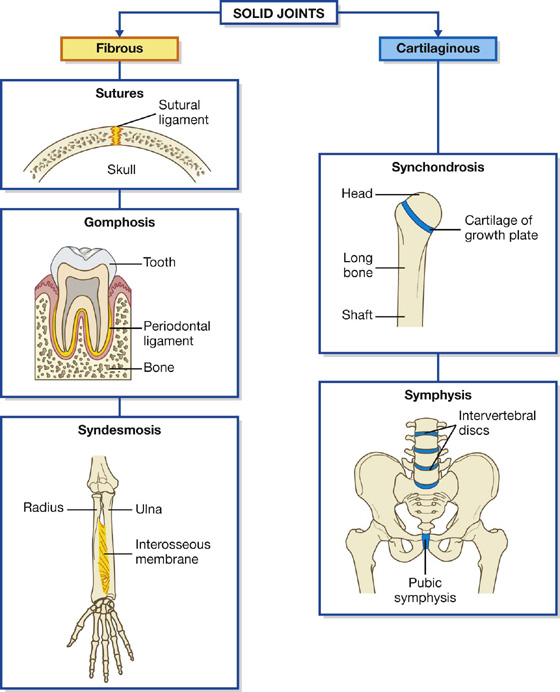
Fig. 1.16 Solid joints.
Fibrous joints include sutures, gomphoses, and syndesmoses.
 Sutures occur only in the skull where adjacent bones are linked by a thin layer of connective tissue termed a sutural ligament.
 Gomphoses occur only between the teeth and adjacent bone. In these joints, short collagen tissue fibers in the periodontal ligament run between the root of the tooth and the bony socket.
 Syndesmoses are joints in which two adjacent bones are linked by a ligament. Examples are the ligamentum flavum, which connects adjacent vertebral laminae, and an interosseus membrane, which links, for example, the radius and ulna in the forearm.
 Cartilaginous joints include synchondroses and symphyses.
 Synchondroses occur where two ossification centers in a developing bone remain separated by a layer of cartilage, for example the growth plate that occurs between the head and shaft of developing long bones. These joints allow bone growth and eventually become completely ossified.
 Symphyses occur where two separate bones are interconnected by cartilage. Most of these types of joints occur in the midline and include the pubic symphysis between the two pelvic bones, and intervertebral discs between adjacent vertebrae.
Clinical app
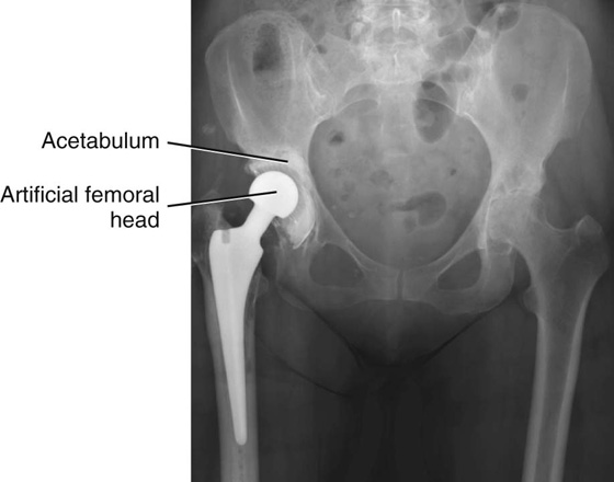
Joint replacement
Joint replacement is undertaken for a variety of reasons. These predominantly include degenerative joint disease and joint destruction. Joints that have severely degenerated or lack their normal function are painful, which can be life limiting, and in otherwise fit and healthy individuals can restrict activities of daily living. In some patients the pain may be so severe that it prevents them from leaving the house and undertaking even the smallest of activities without discomfort.
Large joints are commonly affected, including the hip, knee, and shoulder. However, with ongoing developments in joint replacement materials and surgical techniques, even small joints of the fingers can be replaced.
Typically, both sides of the joint are replaced. In the hip joint the acetabulum will be reamed, and a plastic or metal cup will be introduced. The femoral component will be fitted precisely to the femur and cemented in place (Fig. 1.17).
Clinical app
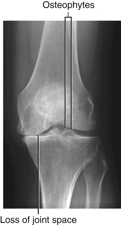
Degenerative joint disease
Degenerative joint disease is commonly known as osteoarthritis or osteoarthrosis. The disorder is related to aging but not caused by aging. Typically, there are decreases in water and proteoglycan content within the cartilage. The cartilage becomes more fragile and more susceptible to mechanical disruption. As the cartilage wears, the underlying bone becomes fissured and also thickens. Synovial fluid may be forced into small cracks that appear in the bone’s surface, which produces large cysts. Furthermore, reactive juxta-articular bony nodules are formed (osteophytes). As these processes occur, there is slight deformation, which alters the biomechanical forces through the joint. This in turn creates abnormal stresses, which further disrupt the joint (Fig. 1.18).
Clinical app
Arthroscopy
Arthroscopy is a technique of visualizing the inside of a joint using a small camera placed through a tiny incision in the skin. Arthroscopy can be performed in most joints. However, it is most commonly performed in the knee, shoulder, ankle, and hip joints. The elbow joint and wrist joint can also be viewed through the arthroscope.
Arthroscopy allows the surgeon to view the inside of the joint and its contents. Notably, in the knee, the menisci and the ligaments are easily seen, and it is possible using separate puncture sites and specific instruments to remove the menisci and repair the cruciate ligaments. The advantages of arthroscopy are that it is performed through small incisions, it enables patients to quickly recover and return to normal activity, and it only requires either a light anesthetic or regional anesthesia during the procedure.
SKIN AND FASCIAS
Skin
The skin is the largest organ of the body. It consists of the epidermis and the dermis. The epidermis is the outer cellular layer of stratified squamous epithelium, which is avascular and varies in thickness. The dermis is a dense bed of vascular connective tissue.
Fascia
Fascia is connective tissue containing varying amounts of fat that separate, support, and interconnect organs and structures, enable movement of one structure relative to another, and allow the transit of vessels and nerves from one area to another. There are two general categories of fascia: superficial and deep.
 Superficial (subcutaneous) fascia lies just deep to and is attached to the dermis of the skin. It is made up of loose connective tissue, usually containing a large amount of fat. The thickness of the superficial fascia (subcutaneous tissue) varies considerably, both from one area of the body to another and from one individual to another. The superficial fascia allows movement of the skin over deeper areas of the body, acts as a conduit for vessels and nerves coursing to and from the skin, and serves as an energy (fat) reservoir.
 Deep fascia usually consists of dense, organized connective tissue. The outer layer of deep fascia is attached to the deep surface of the superficial fascia and forms a thin fibrous covering over most of the deeper region of the body. Inward extensions of this fascial layer form intermuscular septa that compartmentalize groups of muscles with similar functions and innervations. Other extensions surround individual muscles and groups of vessels and nerves, forming an investing fascia. Near some joints the deep fascia thickens, forming retinacula. These fascial retinacula hold tendons in place and prevent them from bowing during movements at the joints. Finally, there is a layer of deep fascia separating the membrane lining the abdominal cavity (the parietal peritoneum) from the fascia covering the deep surface of the muscles of the abdominal wall (the transversalis fascia). This layer is referred to as extraperitoneal fascia. A similar layer of fascia in the thorax is termed the endothoracic fascia.
Clinical app
The importance of fascias
Clinically, fascias are extremely important because they often limit the spread of infection and malignant disease. When infection or malignant diseases cross a fascial plane, a primary surgical clearance may require a far more extensive dissection to render the area free of tumor or infection.
MUSCULAR SYSTEM
The muscular system is generally regarded as consisting of one type of muscle found in the body—skeletal muscle. However, there are two other types of muscle tissue found in the body, smooth muscle and cardiac muscle, which are important components of other systems. These three types of muscle can be characterized by whether they are controlled voluntarily or involuntarily, whether they appear striated (striped) or smooth, and whether they are associated with the body wall (somatic), or with organs and blood vessels (visceral).
 Skeletal muscle forms the majority of the muscle tissue in the body. It consists of parallel bundles of long, multinucleated fibers with transverse stripes, is capable of powerful contractions, and is innervated by somatic and branchial motor nerves. This muscle is used to move bones and other structures, and provides support and gives form to the body. Individual skeletal muscles are often named on the basis of shape (e.g., rhomboid major muscle), attachments (e.g., sternohyoid muscle), function (e.g., flexor pollicis longus muscle), position (e.g., palmar interosseus muscle), or fiber orientation (e.g., external oblique muscle).
 Cardiac muscle is striated muscle found only in the walls of the heart (myocardium) and in some of the large vessels close to where they join the heart. It consists of a branching network of individual cells linked electrically and mechanically to work as a unit. Its contractions are less powerful than those of skeletal muscle and it is resistant to fatigue. Cardiac muscle is innervated by visceral motor nerves.
 Smooth muscle (absence of stripes) consists of elongated or spindle-shaped fibers capable of slow and sustained contractions. It is found in the walls of blood vessels (tunica media), associated with hair follicles in the skin, located in the eyeball, and found in the walls of various structures associated with the gastrointestinal, respiratory, genitourinary, and urogenital systems. Smooth muscle is innervated by visceral motor nerves.
Clinical app
Muscle paralysis
Muscle paralysis is the inability to move a specific muscle or muscle group and may be associated with other neurological abnormalities, including loss of sensation. Paralysis may be due to abnormalities in the brain, the spinal cord, and the nerves supplying the muscles. Paralysis may also be caused by drugs that affect the neurotransmitters at the nerve endings and their action on the muscle themselves. Major causes include stroke, trauma, poliomyelitis, and iatrogenic factors.
In the long term, muscle paralysis will produce secondary muscle wasting and overall atrophy of the region due to disuse.
Clinical app
Muscle atrophy
Muscle atrophy is a wasting disorder of muscle. It can be produced by a variety of causes, which include nerve damage to the muscle, and disuse.
Muscle atrophy is an important problem in patients who have undergone long-term rest or disuse, requiring extensive rehabilitation and muscle-building exercises to maintain normal activities of daily living.
Muscle injuries and strains
Muscle injuries and strains tend to occur in specific muscle groups and usually are related to a sudden exertion and muscle disruption. They typically occur in athletes.
CARDIOVASCULAR SYSTEM
The cardiovascular system consists of the heart, which pumps blood throughout the body, and the blood vessels, which are a closed network of tubes that transport the blood. There are three types of blood vessels:
 arteries, which transport blood away from the heart,
 veins, which transport blood toward the heart,
 capillaries, which connect the arteries and veins, are the smallest of the blood vessels, and are where oxygen, nutrients, and wastes are exchanged within the tissues.
The walls of the blood vessels of the cardiovascular system usually consist of three layers or tunics:
 tunica externa (adventitia)—the outer connective tissue layer,
 tunica media—the middle smooth muscle layer (may also contain varying amounts of elastic fibers in medium and large arteries), and
 tunica intima—the inner endothelial lining of the blood vessels.
Arteries are usually further subdivided into three classes, according to the variable amounts of smooth muscle and elastic fibers contributing to the thickness of the tunica media, the overall size of the vessel, and its function.
 Large elastic arteries contain substantial amounts of elastic fibers in the tunica media, allowing expansion and recoil during the normal cardiac cycle. This helps maintain a constant flow of blood during diastole. Examples of large elastic arteries are the aorta, the brachiocephalic trunk, and the left common carotid artery.
 Medium muscular arteries are composed of a tunica media that contains mostly smooth muscle fibers. This characteristic allows these vessels to regulate their diameter and control the flow of blood to different parts of the body. Examples of medium muscular arteries are most of the named arteries, including the femoral, axillary, and radial arteries.
 Small arteries and arterioles control the filling of the capillaries and directly contribute to the arterial pressure in the vascular system.
Veins also are subdivided into three classes.
 Large veins contain some smooth muscle in the tunica media, but the thickest layer is the tunica externa. Examples of large veins are the superior vena cava, the inferior vena cava, and the portal vein.
 Small and medium veins contain small amounts of smooth muscle, and the thickest layer is the tunica externa. Examples of small and medium veins are superficial veins in the upper and lower limbs and deeper veins of the leg and forearm.
 Venules are the smallest veins and drain the capillaries.
Although veins are similar in general structure to arteries, they have a number of distinguishing features.
 The walls of veins, specifically the tunica media, are thin.
 The luminal diameters of veins are large.
 There often are multiple veins (venae comitantes) closely associated with arteries in peripheral regions.
 Valves often are present in veins, particularly in peripheral vessels inferior to the level of the heart. These are usually paired cusps that facilitate blood flow toward the heart.
Clinical app
Atherosclerosis
Atherosclerosis is a disease that affects arteries. There is a chronic inflammatory reaction in the walls of the arteries, with deposition of cholesterol and fatty proteins. This may in turn lead to secondary calcification, with reduction in the diameter of the vessels impeding distal flow. The plaque itself may be a site for attraction of platelets that may “fall off” (embolize) distally. Plaque fissuring may occur, which allows fresh clots to form and occlude the vessel.
Clinical app
Varicose veins
Varicose veins are tortuous dilated veins that typically occur in the legs, although they may occur in the superficial veins of the arm and in other organs.
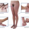
In normal individuals the movement of leg muscles pumps the blood in the veins to the heart. Blood also moves from the superficial veins through the investing layer of fascia of the leg into the deep veins. Valves in these perforating veins may become damaged, allowing blood to pass in the opposite direction. This increased volume and pressure produces dilatation and tortuosity of the superficial veins (Fig. 1.19).
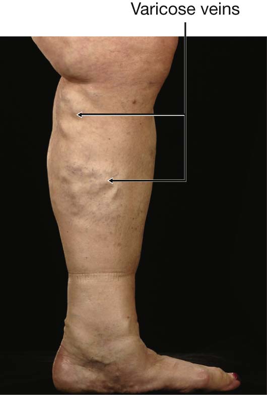
Fig. 1.19 Photograph demonstrating varicose veins.
Anastomoses and collateral circulation
All organs require a blood supply from the arteries and drainage by veins. Within most organs there are multiple ways of perfusing the tissue such that if the main vessel feeding the organ or vein draining the organ is blocked, a series of smaller vessels (collateral vessels) continue to supply and drain the organ.
Some organs have more than one vessel perfusing them, such as the hand, which is supplied by the radial and ulnar arteries. Loss of either the radial or the ulnar artery may not produce any symptoms of reduced perfusion to the hand. The brain also has multiple vessels supplying it, dominated by the carotid arteries and the vertebral arteries. However, vessels within the brain are end arteries and have a poor collateral circulation; hence any occlusion will produce long-term cerebral damage.
Normal vascular anastomoses associated with an organ are important. Some organs, such as the duodenum, have a dual blood supply arising from the branches of the celiac trunk and also from the branches of the superior mesenteric artery. Should either of these vessels be damaged, blood supply to the organ will be maintained.
More specific information about the cardiovascular system and how it relates to the circulation of blood throughout the body will be discussed, where appropriate, in each of the succeeding chapters of the text.
LYMPHATIC SYSTEM
Lymphatic vessels
Lymphatic vessels form an extensive and complex interconnected network of channels, which begin as “porous” blind-ended lymphatic capillaries in tissues of the body and converge to form a number of larger vessels, which ultimately connect with large veins in the root of the neck.
Lymphatic vessels mainly collect fluid lost from vascular capillary beds during nutrient exchange processes and deliver it back to the venous side of the vascular system (Fig. 1.20). Also included in this interstitial fluid that drains into the lymphatic capillaries are pathogens, cells of the lymphocytic system, cell products (such as hormones), and cell debris.
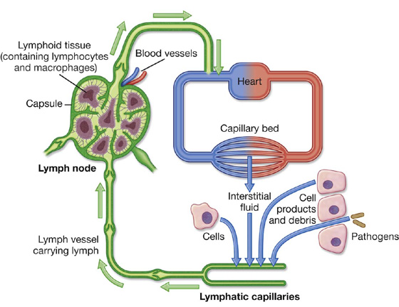
Fig. 1.20 Overview of the structure and function of the lymphatic system.
In the small intestine, certain fats absorbed and processed by the intestinal epithelium are packaged into protein-coated lipid droplets (chylomicrons), which are released from the epithelial cells and enter the interstitial compartment. Together with other components of the interstitial fluid, the chylomicrons drain into lymphatic capillaries (known as lacteals in the small intestine) and are ultimately delivered to the venous system in the neck. The lymphatic system is therefore also a major route of transport for fat absorbed by the gut.
The fluid in most lymphatic vessels is clear and colorless and is known as lymph. That carried by lymphatic vessels from the small intestine is opaque and milky because of the presence of chylomicrons and is termed chyle.
There are lymphatic vessels in most areas of the body except the brain, bone marrow, and avascular tissues such as epithelia and cartilage.
The movement of lymph through the lymphatic vessels is generated mainly by the indirect action of adjacent structures, particularly by contraction of skeletal muscles and pulses in arteries. Unidirectional flow is maintained by the presence of valves in the vessels.
Lymph nodes
Lymph nodes are small (0.1 to 2.5 cm long), encapsulated structures that interrupt the course of lymphatic vessels and contain elements of the body’s defense system, such as clusters of lymphocytes and macrophages. They act as elaborate filters that trap and phagocytose particulate matter in the lymph that percolates through them. In addition, they detect and defend against foreign antigens that are also carried in the lymph.
A number of regions in the body are associated with clusters or a particular abundance of lymph nodes (Fig. 1.21). Not surprisingly, nodes in many of these regions drain the body’s surface, the digestive system, or the respiratory system. All three of these areas are high-risk sites for the entry of foreign pathogens.
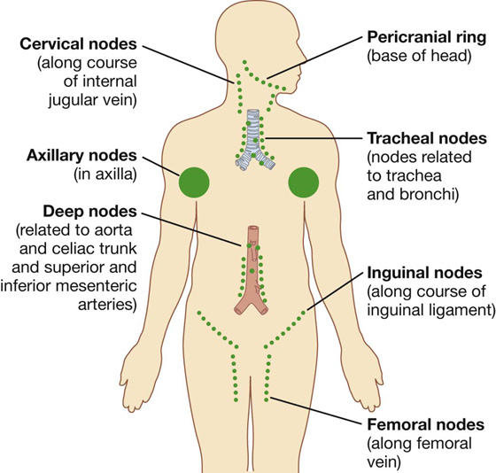
Fig. 1.21 Regions associated with clusters or a particular abundance of lymph nodes.
Lymph nodes are abundant and accessible to palpation in the axilla, the groin and femoral region, and the neck (Fig. 1.21). Deep sites that are not palpable include those associated with the trachea and bronchi in the thorax, and with the aorta and its branches in the abdomen.
Lymphatic trunks and ducts
All lymphatic vessels coalesce to form larger trunks or ducts, which drain into the venous system at sites in the neck where the internal jugular veins join the subclavian veins to form the brachiocephalic veins (Fig. 1.22):
 Lymph from the right side of the head and neck, the right upper limb, right side of the thorax, and right side of the upper and more superficial region of the abdominal wall is carried by lymphatic vessels that connect with veins on the right side of the neck.
 Lymph from all other regions of the body is carried by lymphatic vessels that drain into veins on the left side of the neck.
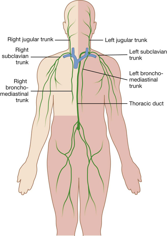
Fig. 1.22 Major lymphatic vessels that drain into large veins in the neck.
Specific information about the organization of the lymphatic system in each region of the body is discussed in the appropriate chapter.
Clinical app
Lymph nodes
Lymph nodes are efficient filters and have an internal honeycomb of reticular connective tissue filled with lymphocytes. These lymphocytes act on bacteria, viruses, and other bodily cells to destroy them. Lymph nodes tend to drain specific areas, and if infection occurs within a drainage area, the lymph node will become active. The rapid cell turnover and production of local inflammatory mediators may cause the node to enlarge and become tender. Similarly, in patients with malignancy, the lymphatics may drain metastasizing cells to the lymph nodes. These can become enlarged and inflamed and will need to be removed if clinically symptomatic.
Lymph nodes may become diffusely enlarged in certain systemic illnesses (e.g., example, viral infection), or local groups may become enlarged with primary lymph node malignancies, such as lymphoma.
NERVOUS SYSTEM
The nervous system can be separated into parts based on structure and on function:
 Structurally, it can be divided into the central nervous system (CNS) and the peripheral nervous system (PNS) (Fig. 1.23).
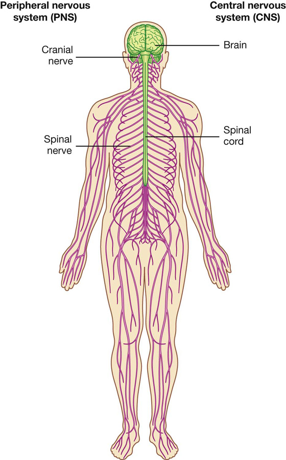
Fig. 1.23 CNS and PNS.
 Functionally, it can be divided into somatic and visceral parts.
The CNS is composed of the brain and spinal cord, both of which develop from the neural tube in the embryo.
The PNS is composed of all nervous structures outside the CNS that connect the CNS to the body. Elements of this system develop from neural crest cells and as outgrowths of the CNS. The PNS consists of the spinal and cranial nerves, visceral nerves and plexuses, and the enteric system. The detailed anatomy of a typical spinal nerve is described in Chapter 2, as is the way spinal nerves are numbered. Cranial nerves are described in Chapter 8. The details of nerve plexuses are described in chapters dealing with the specific regions in which the plexuses are located.
Central nervous system
Brain
The parts of the brain are the cerebral hemispheres, the cerebellum, and the brainstem. The cerebral hemispheres consist of an outer portion, or the gray matter, containing cell bodies; an inner portion, or the white matter, made up of axons forming tracts or pathways; and the ventricles, which are spaces filled with cerebrospinal fluid (CSF).
The cerebellum has two lateral lobes and a midline portion. The components of the brainstem are classically defined as the diencephalon, midbrain, pons, and medulla. However, in common usage today, the term “brainstem” usually refers to the midbrain, pons, and medulla.
A further discussion of the brain can be found in Chapter 8.
Spinal cord
The spinal cord is the part of the CNS in the superior two-thirds of the vertebral canal. It is roughly cylindrical in shape, and is circular to oval in cross-section with a central canal. A further discussion of the spinal cord can be found in Chapter 2.
Meninges
The meninges (Fig. 1.24) are three connective tissue coverings that surround, protect, and suspend the brain and spinal cord within the cranial cavity and vertebral canal. They consist of:
 the dura mater, which is the thickest and most external of the coverings;
 the arachnoid mater, which is against the internal surface of the dura mater;
 the pia mater, which is adherent to the brain and spinal cord.
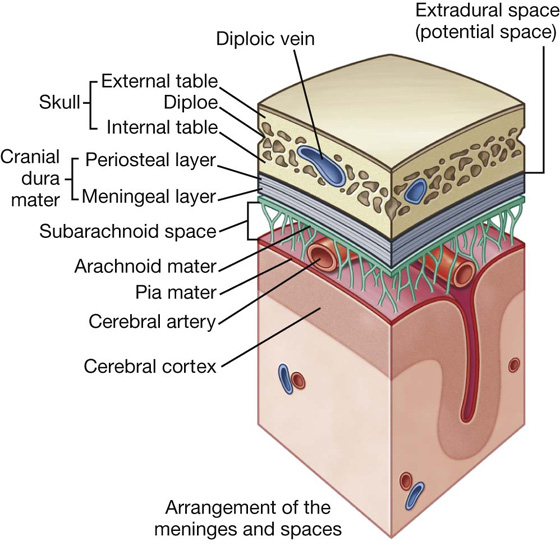
Fig. 1.24 Arrangement of meninges in the cranial cavity.
Between the arachnoid and pia mater is the subarachnoid space, which contains CSF.
A further discussion of the cranial meninges can be found in Chapter 8 and of the spinal meninges in Chapter 2.
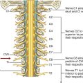
Functional subdivisions of the CNS
Functionally, the nervous system can be divided into somatic and visceral parts.
 The somatic part (soma, from the Greek for “body”) innervates structures (skin and most skeletal muscle) derived from somites in the embryo, and is mainly involved with receiving and responding to information from the external environment.
 The visceral part (viscera, from the Greek for “guts”) innervates organ systems in the body and other visceral elements, such as smooth muscle and glands, in peripheral regions of the body. It is concerned mainly with detecting and responding to information from the internal environment.
Somatic part of the nervous system
The somatic part of the nervous system consists of:
 nerves that carry conscious sensations from peripheral regions back to the CNS, and
 nerves that innervate voluntary muscles.
Somatic nerves arise segmentally along the developing CNS in association with somites, which are themselves arranged segmentally along each side of the neural tube. Part of each somite (the dermatomyotome) gives rise to skeletal muscle and the dermis of the skin. As cells of the dermatomyotome differentiate, they migrate into posterior (dorsal) and anterior (ventral) areas of the developing body.
 Cells that migrate anteriorly give rise to muscles of the limbs and trunk (hypaxial muscles) and to the associated dermis.
 Cells that migrate posteriorly give rise to the intrinsic muscles of the back (epaxial muscles) and the associated dermis.
Developing nerve cells within anterior regions of the neural tube extend processes peripherally into posterior and anterior regions of the differentiating dermatomyotome of each somite (Fig. 1.25).
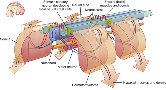
Simultaneously, derivatives of neural crest cells (cells derived from neural folds during formation of the neural tube) differentiate into neurons on each side of the neural tube and extend processes both medially and laterally (Fig. 1.25).
 Medial processes pass into the posterior aspect of the neural tube.
 Lateral processes pass into the differentiating regions of the adjacent dermatomyotome.
Neurons that develop from neurons within the spinal cord are motor neurons and those that develop from neural crest cells are sensory neurons.
Somatic sensory and somatic motor fibers that are organized segmentally along the neural tube become parts of all spinal nerves and some cranial nerves.
The clusters of sensory nerve cell bodies derived from neural crest cells and located outside the CNS form sensory ganglia.
Somatic sensory fibers carry information from the periphery into the CNS and are also called somatic sensory afferents or general somatic afferents (GSAs). The modalities carried by these nerves include temperature, pain, touch, and proprioception. Proprioception is the sense of determining the position and movement of the musculoskeletal system detected by special receptors in muscles and tendons.
Somatic motor fibers carry information away from the CNS to skeletal muscles and are also called somatic motor efferents or general somatic efferents (GSEs). Like somatic sensory fibers that come from the periphery, somatic motor fibers can be very long. They extend from cell bodies in the spinal cord to the muscle cells they innervate.
Dermatomes
Because cells from a specific somite develop into the dermis of the skin in a precise location, somatic sensory fibers originally associated with that somite enter the posterior region of the spinal cord at a specific level and become part of one specific spinal nerve (Fig. 1.26). Each spinal nerve therefore carries somatic sensory information from a specific area of skin on the surface of the body. A dermatome is that area of skin supplied by a single spinal cord level, or on one side, by a single spinal nerve.
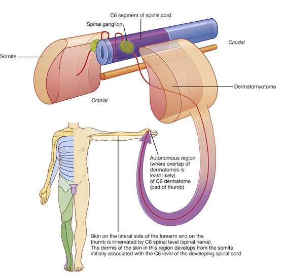
Fig. 1.26 Dermatomes.
There is overlap in the distribution of dermatomes, but usually a specific region within each dermatome can be identified as an area supplied by a single spinal cord level. Testing touch in these autonomous zones in a conscious patient can be used to localize lesions to a specific spinal nerve or to a specific level in the spinal cord.
Myotomes
Somatic motor nerves that were originally associated with a specific somite emerge from the anterior region of the spinal cord and, together with sensory nerves from the same level, become part of one spinal nerve. Therefore each spinal nerve carries somatic motor fibers to muscles that originally developed from the related somite. A myotome is that portion of a skeletal muscle innervated by a single spinal cord level or, on one side, by a single spinal nerve.
Myotomes are generally more difficult to test than dermatomes, because each skeletal muscle in the body is usually innervated by nerves derived from more than one spinal cord level (Fig. 1.27).
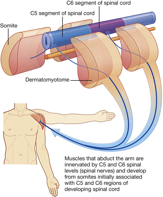
Fig. 1.27 Myotomes.
Visceral part of the nervous system
The visceral part of the nervous system, as in the somatic part, consists of motor and sensory components:
Clinical app
Dermatomes and myotomes
A knowledge of dermatomes and myotomes is absolutely fundamental to carrying out a neurological examination. A typical dermatome map is shown in Fig. 1.28.
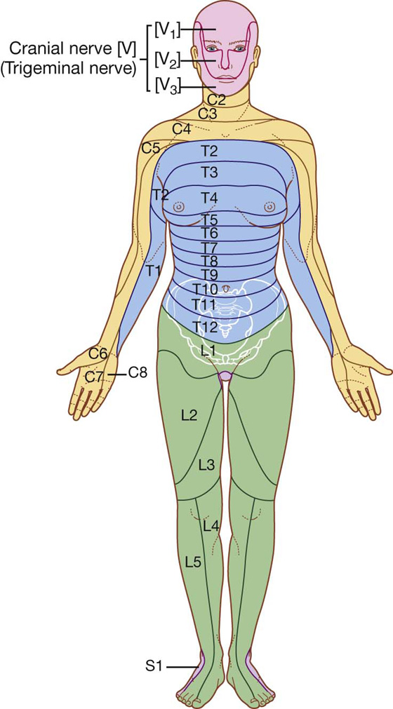
Fig. 1.28 Dermatomes (anterior view).
Clinically, a dermatome is that area of skin supplied by a single nerve or spinal cord level. A myotome is that region of skeletal muscle innervated by a single nerve or spinal cord level. Most individual muscles of the body are innervated by more than one spinal cord level, so the evaluation of myotomes is usually accomplished by testing movements of joints or muscle groups.
 Sensory nerves monitor changes in the viscera.
 Motor nerves mainly innervate smooth muscle, cardiac muscle, and glands.
The visceral motor component is commonly referred to as the autonomic division of the PNS and is subdivided into sympathetic and parasympathetic parts.
Like the somatic part of the nervous system, the visceral part is segmentally arranged and develops in a parallel fashion (Fig. 1.29).
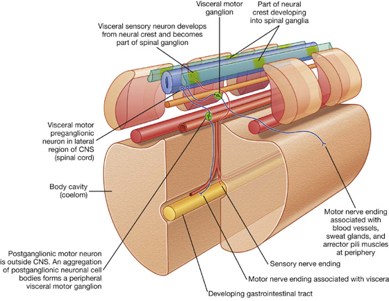
Fig. 1.29 Development of the visceral part of the nervous system.
Visceral motor neurons that arise from cells in lateral regions of the neural tube send processes out of the anterior aspect of the tube. Unlike in the somatic part, these processes, containing general visceral efferent fibers (GVEs), synapse with other cells—usually other visceral motor neurons—that develop outside the CNS from neural crest cells that migrate away from their original positions close to the developing neural tube.
The visceral motor neurons located in the spinal cord are referred to as preganglionic motor neurons and their axons are called preganglionic fibers; the visceral motor neurons located outside the CNS are referred to as postganglionic motor neurons and their axons are called postganglionic fibers.
The cell bodies of the visceral motor neurons outside the CNS often associate with each other in a discrete mass called a ganglion.
Visceral sensory and motor fibers enter and leave the CNS with their somatic equivalents (Fig. 1.30). Visceral sensory fibers enter the spinal cord together with somatic sensory fibers through posterior roots of spinal nerves. Preganglionic fibers of visceral motor neurons exit the spinal cord in the anterior roots of spinal nerves along with fibers from somatic motor neurons.
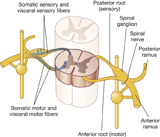
Fig. 1.30 Basic anatomy of a thoracic spinal nerve.
Postganglionic fibers traveling to visceral elements in the periphery are found in the posterior and anterior rami (branches) of spinal nerves.
Visceral motor and sensory fibers that travel to and from viscera form named visceral branches that are separate from the somatic branches. These nerves generally form plexuses from which arise branches to the viscera.
Visceral motor and sensory fibers do not enter and leave the CNS at all levels (Fig. 1.31):
 In the cranial region, visceral components are associated with 4 of the 12 cranial nerves (CN III, VII, IX, and X).
 In the spinal cord, visceral components are associated mainly with spinal cord levels T1 to L2 and S2 to S4.
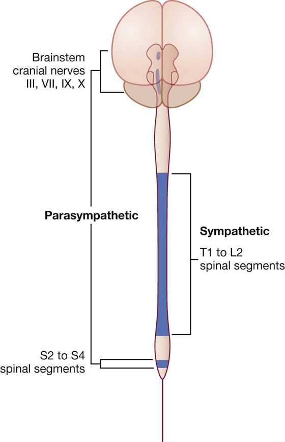
Fig. 1.31 Parts of the CNS associated with visceral motor components.
Visceral motor components associated with spinal levels T1 to L2 are termed sympathetic. Those visceral motor components in cranial and sacral regions, on either side of the sympathetic region, are termed parasympathetic:
 the sympathetic system innervates structures in peripheral regions of the body and viscera;
 the parasympathetic system is more restricted to innervation of the viscera only.
Sympathetic system
The sympathetic part of the autonomic division of the PNS leaves thoracolumbar regions of the spinal cord with the somatic components of spinal nerves T1 to L2 (Figs. 1.31, 1.32). On each side, a paravertebral sympathetic trunk extends from the base of the skull to the inferior end of the vertebral column where the two trunks converge anteriorly to the coccyx at the ganglion impar. Each trunk is attached to the anterior rami of spinal nerves and becomes the route by which sympathetics are distributed to the periphery and all viscera.
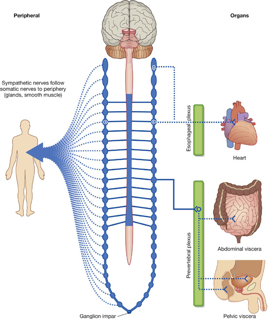
Fig. 1.32 Sympathetic part of the autonomic division of the PNS.
Visceral motor preganglionic fibers leave the T1 to L2 part of the spinal cord in anterior roots. The fibers then enter the spinal nerves, pass through the anterior rami and into the sympathetic trunks. One trunk is located on each side of the vertebral column (paravertebral) and positioned anterior to the anterior rami. Along the trunk is a series of segmentally arranged ganglia formed from collections of postganglionic neuronal cell bodies where the preganglionic neurons synapse with postganglionic neurons. Anterior rami of T1 to L2 are connected to the sympathetic trunk or to a ganglion, by a white ramus communicans, which carries preganglionic sympathetic fibers and appears white because the fibers it contains are myelinated (Fig. 1.33).
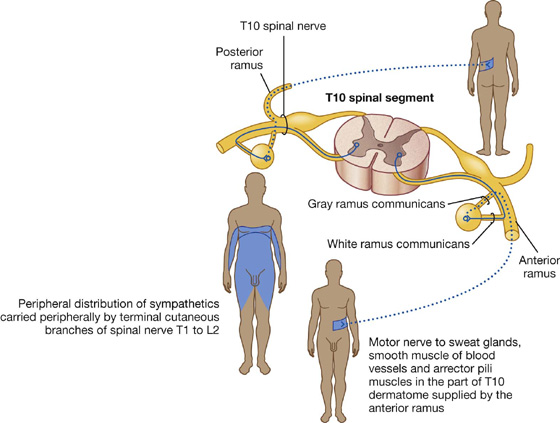
Preganglionic sympathetic fibers that enter a paravertebral ganglion or the sympathetic trunk through a white ramus communicans may take the following four pathways to target tissues:
1. Peripheral sympathetic innervation at the level of origin of the preganglionic fiber
Preganglionic sympathetic fibers may synapse with postganglionic motor neurons in ganglia associated with the sympathetic trunk, after which postganglionic fibers enter the same anterior ramus and are distributed with peripheral branches of the posterior and anterior rami of that spinal nerve (Fig. 1.33). The fibers innervate structures at the periphery of the body in regions supplied by the spinal nerve. The gray ramus communicans connects the sympathetic trunk or a ganglion to the anterior ramus and contains the postganglionic sympathetic fibers. It appears gray because postganglionic fibers are nonmyelinated. The gray ramus communicans is positioned medial to the white ramus communicans.
2. Peripheral sympathetic innervation above or below the level of origin of the preganglionic fiber
Preganglionic sympathetic fibers may ascend or descend to other vertebral levels where they synapse in ganglia associated with spinal nerves that may or may not have visceral motor input directly from the spinal cord (i.e., those nerves other than T1 to L2) (Fig. 1.34).
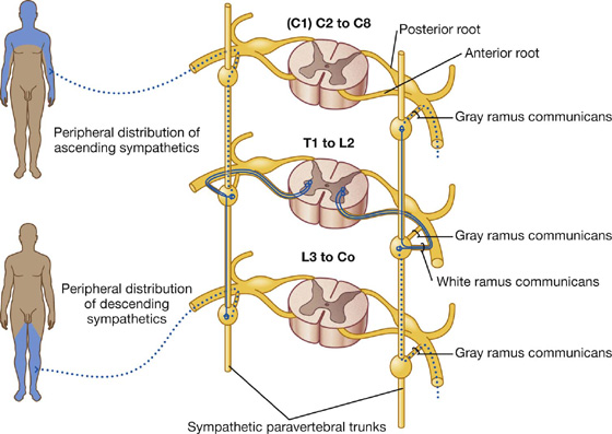
The postganglionic fibers leave the distant ganglia via gray rami communicantes and are distributed along the posterior and anterior rami of the spinal nerves.
The ascending and descending fibers, together with all the ganglia, form the paravertebral sympathetic trunk, which extends the entire length of the vertebral column (Fig. 1.32). The formation of this trunk, on each side, enables visceral motor fibers of the sympathetic part of the autonomic division of the PNS, which ultimately emerge from only a small region of the spinal cord (T1 to L2), to be distributed to peripheral regions innervated by all spinal nerves.
White rami communicantes only occur in association with spinal nerves T1 to L2, whereas gray rami communicantes are associated with all spinal nerves.
Fibers from spinal cord levels T1 to T5 pass predominantly superiorly, whereas fibers from T5 to L2 pass inferiorly. All sympathetics passing into the head have preganglionic fibers that emerge from spinal cord level T1 and ascend in the sympathetic trunks to the highest ganglion in the neck (the superior cervical ganglion), where they synapse. Postganglionic fibers then travel along blood vessels to target tissues in the head, including blood vessels, sweat glands, small smooth muscles associated with the upper eyelids, and the dilator of the pupil.
3. Sympathetic innervation of thoracic and cervical viscera
Preganglionic sympathetic fibers may synapse with postganglionic motor neurons in ganglia and then leave the ganglia medially to innervate thoracic or cervical viscera (Fig. 1.35). They may ascend in the trunk before synapsing; after synapsing, the postganglionic fibers may combine with those from other levels to form named visceral nerves, such as cardiac nerves. Often, these nerves join branches from the parasympathetic system to form plexuses on or near the surface of the target organ; for example, the cardiac and pulmonary plexuses. Branches of the plexus innervate the organ. Spinal cord levels T1 to T5 mainly innervate cranial, cervical, and thoracic viscera.
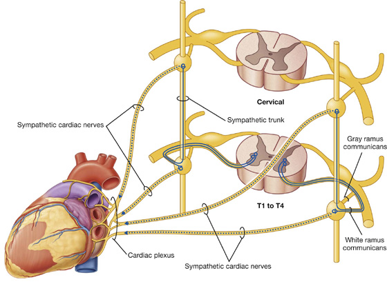
Fig. 1.35 Course of sympathetic nerves traveling to the heart.
4. Sympathetic innervation of the abdomen and pelvic regions and the adrenals
Preganglionic sympathetic fibers may pass through the sympathetic trunk and paravertebral ganglia without synapsing and, together with similar fibers from other levels, form splanchnic nerves (greater, lesser, least, lumbar, and sacral), which pass into the abdomen and pelvic regions (Fig. 1.36). The preganglionic fibers in these nerves are derived from spinal cord levels T5 to L2.
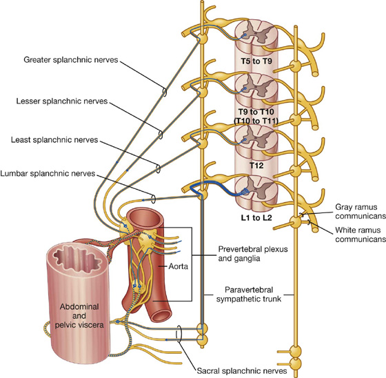
Fig. 1.36 Course of sympathetic nerves traveling to abdominal and pelvic viscera.
The splanchnic nerves generally connect with sympathetic ganglia around the roots of major arteries that branch from the abdominal aorta. These ganglia are part of a large prevertebral plexus that also has input from the parasympathetic part of the autonomic division of the PNS. Postganglionic sympathetic fibers are distributed in extensions of this plexus, predominantly along arteries, to viscera in the abdomen and pelvis.
Some of the preganglionic fibers in the prevertebral plexus do not synapse in the sympathetic ganglia of the plexus, but pass through the system to the adrenal gland where they synapse directly with cells of the adrenal medulla. These cells are homologues of sympathetic postganglionic neurons and secrete adrenaline and noradrenaline into the vascular system.
Parasympathetic system
The parasympathetic part of the autonomic division of the PNS (Fig. 1.37) leaves cranial and sacral regions of the CNS in association with:
 cranial nerves III, VII, IX, and X: III, VII, and IX carry parasympathetic fibers to structures within the head and neck only, whereas X (the vagus nerve) also innervates thoracic and most abdominal viscera; and
 spinal nerves S2 to S4: sacral parasympathetic fibers innervate inferior abdominal viscera, pelvic viscera, and the arteries associated with erectile tissues of the perineum.
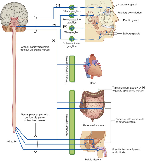
Fig. 1.37 Parasympathetic part of the autonomic division of the PNS.
Like the visceral motor nerves of the sympathetic part, the visceral motor nerves of the parasympathetic part generally have two neurons in the pathway. The preganglionic neurons are in the CNS, and fibers leave in the cranial nerves or pelvic splanchnic nerves.
Sacral preganglionic parasympathetic fibers
In the sacral region, the preganglionic parasympathetic fibers form special visceral nerves (the pelvic splanchnic nerves), which originate from the anterior rami of S2 to S4 and enter pelvic extensions of the large prevertebral plexus formed around the abdominal aorta. These fibers are distributed to pelvic and abdominal viscera mainly along blood vessels. The postganglionic motor neurons are in the walls of the viscera. In organs of the gastrointestinal system, preganglionic fibers do not have a postganglionic parasympathetic motor neuron in the pathway; instead, preganglionic fibers synapse directly on neurons in the ganglia of the enteric system.
Cranial nerve preganglionic parasympathetic fibers
The preganglionic parasympathetic motor fibers in CN III, VII, and IX separate from the nerves and connect with one of four distinct ganglia, which house postganglionic motor neurons. These four ganglia are near major branches of the trigeminal nerve [V]. Postganglionic fibers leave the ganglia, join the branches of the trigeminal nerve [V], and are carried to target tissues (salivary, mucous, and lacrimal glands; constrictor muscle of the pupil; and ciliary muscle in the eye) with these branches.
The vagus nerve [X] gives rise to visceral branches along its course. These branches contribute to plexuses associated with thoracic viscera or to the large prevertebral plexus in the abdomen and pelvis. Many of these plexuses also contain sympathetic fibers.
When present, postganglionic parasympathetic neurons are in the walls of the target viscera.
Visceral sensory innervation (visceral afferents)
Visceral sensory fibers generally accompany visceral motor fibers.
Visceral sensory fibers accompanying sympathetic fibers
Visceral sensory fibers follow the course of sympathetic fibers entering the spinal cord at similar spinal cord levels. However, visceral sensory fibers may also enter the spinal cord at levels other than those associated with motor output. For example, visceral sensory fibers from the heart may enter at levels higher than spinal cord level T1. Visceral sensory fibers that accompany sympathetic fibers are mainly concerned with detecting pain.
Visceral sensory fibers accompanying parasympathetic fibers
Visceral sensory fibers accompanying parasympathetic fibers are carried mainly in the glossopharyngeal nerve [IX] and the vagus nerve [X] and in spinal nerves S2 to S4. These fibers primarily relay information to the CNS about the status of normal physiological processes and reflex activities.
Visceral sensory fibers in the vagus nerve [X] include those from cervical viscera, and major vessels and viscera in the thorax and abdomen.
Visceral sensory fibers from pelvic viscera and the distal parts of the colon are carried in S2 to S4.
The enteric system
The enteric nervous system consists of motor and sensory neurons and their support cells, which form two interconnected plexuses, the myenteric and submucous nerve plexuses, within the walls of the gastrointestinal tract (Fig. 1. 38). Each of these plexuses is formed by:
 ganglia, which house the nerve cell bodies and associated cells; and
 bundles of nerve fibers, which pass between ganglia and from the ganglia into surrounding tissues.
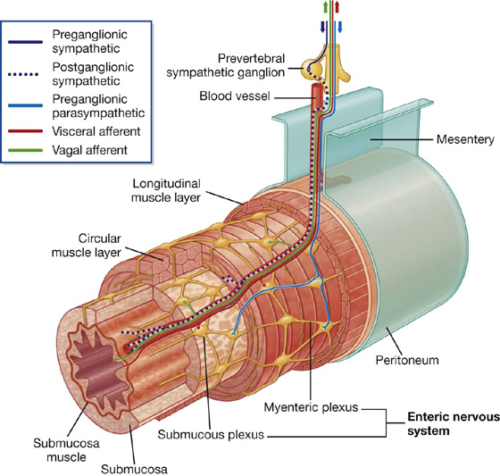
Fig. 1.38 Enteric part of the nervous system.
Neurons in the enteric system are derived from neural crest cells originally associated with occipitocervical and sacral regions. Interestingly, more neurons are reported to be in the enteric system than in the spinal cord itself.
Sensory and motor neurons within the enteric system control reflex activity within and between parts of the gastrointestinal system. These reflexes regulate peristalsis, secretomotor activity, and vascular tone. These activities can occur independently of the brain and spinal cord, but can also be modified by input from preganglionic parasympathetic and postganglionic sympathetic fibers.
Sensory information from the enteric system is carried back to the CNS by visceral sensory fibers.
Clinical app
Referred pain
Referred pain occurs when sensory information comes to the spinal cord from one location, but is interpreted by the CNS as coming from another location innervated by the same spinal cord level. Usually, this happens when the pain information comes from a region, such as the gut, which has a low amount of sensory output. These afferents converge on neurons at the same spinal cord level that receive information from the skin, which is an area with a high amount of sensory output. As a result, pain from the normally low output region is interpreted as coming from the normally high output region.
Pain is most often referred from a region innervated by the visceral part of the nervous system to a region innervated, at the same spinal cord level, by the somatic side of the nervous system.
Pain can also be referred from one somatic region to another. For example, irritation of the peritoneum on the inferior surface of the diaphragm, which is innervated by the phrenic nerve, can be referred to the skin on the top of the shoulder, which is innervated by other somatic nerves arising at the same spinal cord level.
Nerve plexuses
Nerve plexuses are either somatic or visceral and combine fibers from different sources or levels to form new nerves with specific targets or destinations (Fig. 1.39). Plexuses of the enteric system also generate reflex activity independent of the CNS.
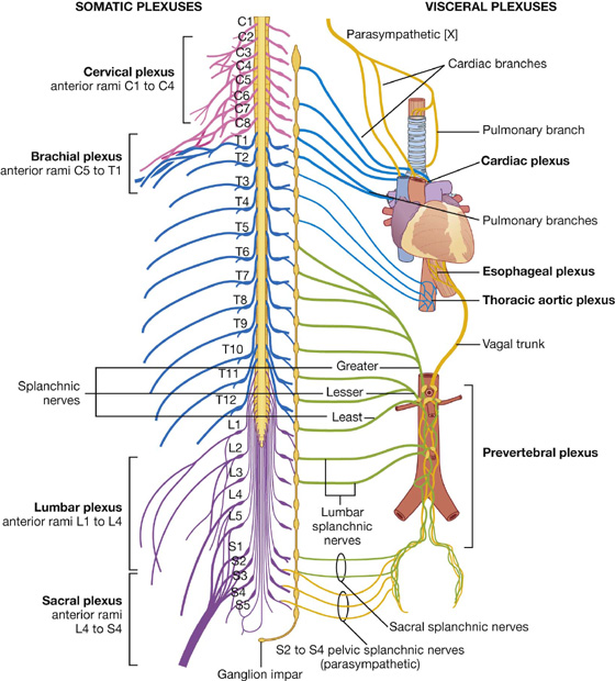
Fig. 1.39 Nerve plexuses.
Somatic plexuses
Major somatic plexuses formed from the anterior rami of spinal nerves are the cervical (C1 to C4), brachial (C5 to T1), lumbar (L1 to L4), sacral (L4 to S4), and coccygeal (S5 to Co) plexuses (Fig. 1.39). Except for spinal nerve T1, the anterior rami of thoracic spinal nerves remain independent and do not participate in plexuses.
Visceral plexuses
Visceral nerve plexuses are formed in association with viscera and generally contain efferent (sympathetic and parasympathetic) and afferent components (Fig. 1.39). These plexuses include cardiac and pulmonary plexuses in the thorax, and a large prevertebral plexus in the abdomen anterior to the aorta, which extends inferiorly onto the lateral walls of the pelvis. The massive prevertebral plexus supplies input to and receives output from all abdominal and pelvic viscera.
OTHER SYSTEMS
Specific information about the organization and components of the respiratory, gastrointestinal, and urogenital systems will be discussed in each of the succeeding chapters of this text.