[level-membership-for-physical-medicine-and-rehabilitation-category]
CHAPTER 24 Technique of Radiofrequency Denervation
INTRODUCTION
History
The use of electrical current to create lesions for the treatment of pain began in 1931, when Kirschner introduced it for the treatment of trigeminal neuralgia.1 In 1965, Mullan used direct current to perform percutaneous lateral cordotomy for unilateral malignant pain.2 Later that year, Rosomoff modified this technique and used radiofrequency (RF) current for this treatment.3 An RF current was found to produce more predictable, circumscribing lesions. Several years later, Sweet and Wepsic described their technique for the use of RF lesions of the Gasserian ganglion in the treatment of trigeminal neuralgia.4 In spinal pain, the use of RF current was reported in a series of cases by Shealy (1975).5 He described RF lesioning of the medial branch to treat lumbar facet joint pain. Subsequently, more options for the use of RF lesioning in various spinal pain syndromes were introduced into clinical practice.6–8 The introduction of a small-diameter (22-gauge) temperature monitoring electrode system by Sluijter and Mehta in 19819 increased the safety of the current method used.10 Since then, RF procedures have been widely adopted by many pain practitioners. In addition there have been many new technical developments, such as the improvement of the quality of C-arm image intensifiers. All these developments have contributed to a widespread use of RF lesioning.
Recently, a modification of the traditional RF method was introduced by Sluijter et al.11 They used the same output setting of the lesion generator that was used for making heat lesions as in RF lesioning, but they interrupted this output to allow generated heat to be washed out by thermal conductivity and circulation. This technique is called ‘pulsed radiofrequency’ (PRF) and is claimed to be nondestructive. Until now, there are no reports of any sensory or motor loss following this procedure. However, it is too soon to categorically recommend this technique because the mechanism of action is still unknown. Until several double-blind, randomized, controlled trials are conducted this new approach should not be routinely employed.
Physics
Radiofrequency current
An RF current is applied by an RF lesion generator through an electrode, which is insulated except for the most distal part. This exposed region is the active portion of the electrode. The RF current flows from the electrode tip to the dispersive ground plate, which is placed on the arm or leg of the patient and leads the current back to the RF lesion generator. RF current flows through tissue and results in an electric field. This electric field places an electric force on the ions within tissue electrolytes, causing them to oscillate at a high rate (i.e. 300 000 times per second).12 Tissue heating is created by frictional dissipation of the ionic current within the fluid medium, which heats the electrode.
Lesion size
The size of the lesion not only depends on the diameter of electrode and the length of the uninsulated electrode tip, but also depends on tip temperature. This was confirmed in animal studies by Cosman et al. in 1984.13 Bogduk et al. studied not only the size of the lesions, but also the shape of the lesion.14 They performed experimental lesions in egg white and fresh meat. They found that RF lesions do not extend distal to the tip of the electrode, but extend radially around the active electrode tip in a spheroidal shape. Based on these observations, Bogduk suggested that the best placement of the electrode tip was parallel to the target structure.
Other research methods involving computerized or mathematical modeling of similar experiments have been used. For example, Moringlane et al. studied experimental RF coagulation with a computer-based on-line monitoring of temperature and power.15 Vinas et al. also studied lesion size in vivo using fresh eggs and in vitro using the subcortical white matter of rabbits.16 Both investigators obtained results that were similar to those reported by Bogduk et al. Once equilibrium temperature is reached (after 20–40 seconds), the size of the lesion does not increase. However, some variables such as circulation effect and the tissue heat conductivity may also produce a variation in lesion size, but are unpredictable.13 Consequently, the lesion size may therefore be variable at different locations within the body.
Radiofrequency lesion generator
The modern RF lesion generating system has different functions, including a pulsed RF mode. There is continuous on-line impedance measurement to confirm continuity of the electrical circuit and to detect any short circuits. One of the key components of the system is nerve stimulator function. It is used to confirm the proper position of electrode tip (it indicates the electrode-to-nerve distance) and to permit minor adjustments. To ensure the proximity of the active tip to the sensory fibers, stimulation is performed at 50 Hz. The 2 Hz stimulation is carried out to detect extraspinal muscle contractions that occur when the needle is placed too close to a nerve root motor fiber. Voltage, current, and wattage during an RF procedure are also monitored. Finally, a generator monitors temperature using a thermocouple. This is an important lesion parameter, but the temperature is only measured at the tip of the electrode and not in the more peripheral zones of the lesion area. The usefulness of tip temperature to monitor the lesion size is minimized because the lesion size is dependent on local blood circulation. There is a rapid drop in temperature over the first few millimeters from the electrode tip.13,17
Effect of radiofrequency current on nerve tissue
The effect of RF lesions on nerve tissue is controversial. Letcher and Goldring, in 1968, investigated the effect of RF current and heat on the nerve action potential of the saphenous nerve in cats.18 Delta and C-fibers were blocked before the alpha-beta group by both RF current and heat. Uematsu,19 and subsequently Smith et al.,20 reported quite disparate results. Smith et al. created RF lesions of different temperatures by placing an electrode into the lumbar intervertebral foramina of dogs.20 Indiscriminate damage of both small and large fibers by RF current was observed. Uematsu conducted a histological analysis of feline sciatic nerves that sustained RF thermocoagulation.19 These studies have been criticized because large, 14-gauge electrodes were used; in addition, they were placed close to the dorsal root ganglion during open surgery. However, these methods are not comparable to the technique which is commonly used in clinical practice today, since 22-gauge needles where not available at that time.21 In response to this critique, de Louw et al., in 2001, tried to investigate morphological effects of RF lesions as they develop in normal clinical situations.21 A percutaneous RF lesion adjacent to the dorsal root ganglion (DRG) of goats was created with a 22-gauge electrode at a tip temperature of 67°C. Immunocytochemical changes indicative of proliferation and regeneration was observed 2 weeks after the RF lesion was created. These alterations occurred outside the DRG, without interfering with the function of large myelinated fibers.
Effect of pulsed radiofrequency current on nerve tissue
Recently, the importance of heat as the definitive mechanism of action RF lesioning has been questioned.11 In 1998, Sluijter et al. investigated isothermic RF lesioning also termed pulsed RF (PRF) treatment.11 Ostensibly, PRF generates its therapeutic effects independent of thermal factors. The pulses are given at a rate of 2 Hz and last 20 msec. The rest period is 480 msec, and this allows the generated heat to be washed out by thermal conductivity and circulation.
The mechanism by which pulsed RF treatment effects symptom relief remains unknown. In 2002, Higuchi et al. undertook a study to elucidate this mechanism. They attempted to identify spinal cord neuron activation following the exposure of the dorsal ganglion of rats to PRF currents.22 A significant increase in the number of cFos-immunoreactive neurons in the superficial laminae of the dorsal horn was observed. This finding indicates that PRF current activates pain-processing neurons in the dorsal horn and that this effect is not mediated by tissue heating.
This technique is considered to be a safer method of treatment because until now the observations showed no signs of neurodestruction and thus neurological side effects.11,23 Cahana et al., in 2003, compared the acute effects of pulsed versus continuous RF energy on impulse propagation and synaptic transmission in hippocampal slice cultures and on cell survival in cortical cultures of rats.24 In both systems, they found an induction of distance-dependent tissue destruction under the stimulating needle (namely, an inhibition of evoked synaptic activity), but this was more pronounced in the continuous RF group. Thus, they concluded that the acute effects of PRF are more reversible and less destructive in nature than the acute effects of classic continuous RF mode.
RADIOFREQUENCY DENERVATION IN THE CERVICAL REGION
Cervical percutaneous radiofrequency denervation of the facet joints
Relevant anatomy
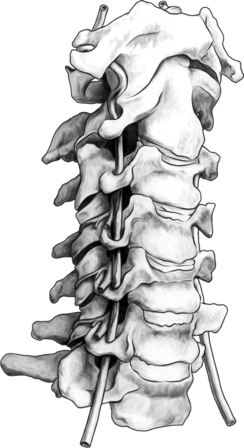
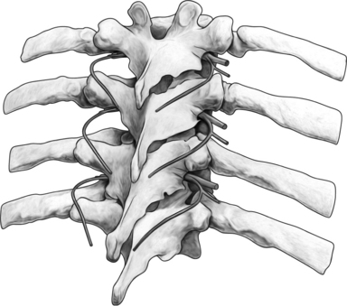
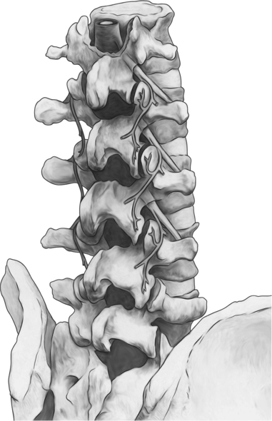
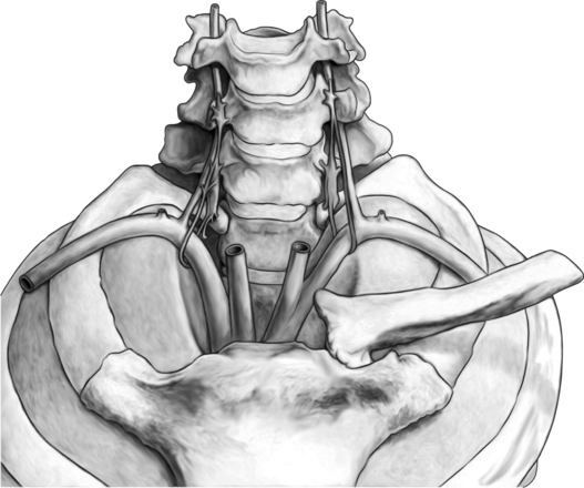
The cervical zygapophyseal joints are innervated in the same way as the lumbar zygapophyseal joints (Fig. 24.1). The cervical segmental nerves divide into the primary anterior ramus and the primary posterior ramus on exiting the neuroforamen. Immediately, the posterior branch divides into a lateral and a medial branch in the cervical intertransverse space. The medial branches of C4 to C8 run dorsally and medially through the ‘waist’ of their respective articular pillars. They innervate the facet joints at the level of the exiting segmental nerve and at the level below. Because of this multilevel innervation of the facet joints, usually the medial branch procedure is performed at several levels. Furthermore, the medial branches give deep branches to multifidus muscles and superficial branches to semispinal cervical muscles.
Procedure
Sedation is not employed because of the need for continuous communication between practitioner and patient. Several approaches to reach the medial branch of the dorsal ramus at the upper and middle cervical area can be used.
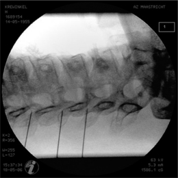
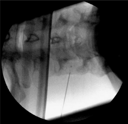
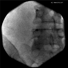
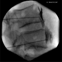
The most commonly used approach by these authors is the posterolateral approach.25 For this technique, the patient is positioned supine on the operating table, which is tolerated well. The occiput is placed on a headrest and the cervical spine is slightly extended. The C-arm is positioned in a moderately oblique (±30°) location to secure a safe distance between the electrode tip and the exiting segmental nerve. In this position the gantry angle is parallel to the axis of the intervertebral foramen that is upward and slightly caudal. In this position the segmental nerves exit in a plane approximately perpendicular to the monitor screen. The degree of obliquity should be such that the projection of the pedicles is seen a little anterior to 50% of the vertebral body (Fig. 24.2). In the frontal plane, there should be a small angle of the C-arm with the transverse plane. This provides clear visibility of the intervertebral discs and the neuroforamina. In this projection, the medial branch runs over the base of the superior articular process, which is easily viewed. Entry points are marked on the skin, somewhat posterior and caudal to the target points as seen on the monitor, i.e. dorsal from the posterior border of the facet column and slightly caudal. Care should be taken to ensure that the entry point is not too anterior in the neck to avoid important vascular structures such as the carotid artery. The first needle (preferably the most cranial) is inserted in a horizontal plane and in a slightly cranial direction not deeper than 2 cm, so that the needle point is in line with the target point. Then the needle is carefully advanced anteriorly and cranially until bone contact is made with the facet column at the target point (see Fig. 24.2).
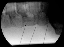
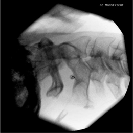
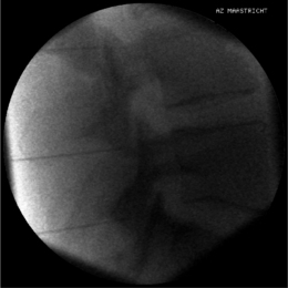
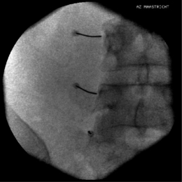
The position of the C-arm in the AP direction should confirm the position of the needle tip adjacent to the concavity (‘waist’) of the articular pillars of the cervical spine at the corresponding level (Fig. 24.3). Once the first needle is in the proper position, the other needles are introduced in the same way as described above. The authors prefer to take advantage of the first needle serving as an indicator for the direction and depth for subsequent needles, which accounts for their recommendation of placing all needles before applying RF rather than lesioning a single medial branch and then placing the next needle. The technique is identical for the facet joints from C3–4 until C6–7. The direction of the needle at the C2 level is different. It should be oriented toward the small branches that innervate the C2–3 facet joint and not toward the medial branch, which is the greater occipital nerve. For the RF treatment of this facet joint, the needle should be placed at the arch of C2 at the level of the upper border of foramen C3.
When optimal anatomical localization of the needles transpires, an electrical stimulation is performed to confirm correct needle position, i.e. parallel to the medial branch. This can be accomplished by identifying the stimulation thresholds. First, an electrical stimulation rate of 50 Hz should be given and should elicit a response (tingling sensation) in the neck at less than 0.5 volts. Next, a stimulation at 2 Hz is performed to confirm accurate needle position. Contractions of the paraspinal muscles will be noticed. Muscle contractions in the arm indicate needle placement too close to the exciting nerve root. In that case the needle should be repositioned more posteriorly. Once proper positioning of the needle is confirmed, the medial branch of the dorsal ramus is anesthetized with 1–2 mL local anesthetic solution (lidocaine 1–2%). An 80°C radiofrequency thermal lesion is made for 60 seconds at each level. To date, there have been no reported complications from cervical facet joint denervation when the procedure is methodically performed.26
Some postoperative burning pain is described in >30% of patients.27 It disappears spontaneously after 1–3 weeks. One should always bear in mind that there is risk of puncture of the vertebral artery when the needle is positioned anterior to the foramen in the posterolateral approach.
A second approach, which is more popular in the United States, is the posterior approach of the facet joint. This was first introduced by Lord et al. in 1995.28 In this technique, the patient is positioned prone on the operating table, with the head flexed (about 5–10°) and with the face resting on a padded ring. This is a ‘tunnel vision’ technique, in which the target points are the posterior aspects of the waists of the articular pillars at the levels to be blocked and are the same as the entry points. The needle is introduced from posterior of the neck to make contact with each of the two nerves supplying the painful joints. When bone contact is made, the C-arm is turned to give a lateral view in which the needle tip should be seen in the posterior aspect of the waist of the articular pillar. A deviation toward the midline should be avoided because of risk of penetration into the epidural and subarachnoid space. Subsequently, the needle is incrementally advanced until the tip is projecting at the center of the pedicle. Then, a slightly lateral deviation should be made so that the needle tip is in the most lateral aspect of the articular pillar in the posteroanterior view. When this position is confirmed, stimulation is performed as described above to determine the 50 Hz and 2 Hz thresholds. If these are acceptable, local anesthetic is injected and an RF lesion (80°C for 60 sec) is made. At each location two lesions are made: the second one after a rotation of the RF needle over 90° from its first position.
Equipment
Different radiofrequency lesioning probes can be used. A SMK-C5 (Sluijter-Mehta Kit, 22-gauge, 50 mm) cannula with a 4 mm active tip or, alternatively, an RCN-6 (24-gauge, 60 mm) needle is used. The advantage of an SMK needle is its ability to measure temperature, but there is the risk of displacement of the needle while inserting the RF probe. The RCN-6 electrode has a connecting tube that allows injection of local anesthetics before lesioning, minimizing potential displacement of the needle once it is positioned. There is no temperature measurement while using the RCN-6 electrode, but this is not thought to be a critical issue, although recently Buijs et al. reported that lesion size is more predictable while measuring the temperature.29 A 10 cm, 22-gauge SMK-electrode with a 4 mm tip is used for the posterior approach. With an SMK probe, an 80°C radiofrequency thermal lesion is made for 60 seconds at each level. With a RCN-6 needle, 20 volts over 60 seconds is applied to the electrode, which should heat the electrode tip to the correct temperature.
Postprocedure care
The patient is allowed to go home immediately after the procedure. A feeling of dizziness and vertigo is frequently described, especially after the higher median branch blocks. RF of the third occipital nerve secondarily can partially block the upper cervical proprioceptive afferents and can result in transient ataxia and unsteadiness.30,31 When this situation can possibly occur, patient should be advised not to drive a car or handle other dangerous machinery for the initial 24 hours following the procedure.
Cervical radiofrequency lesioning of the dorsal root ganglion
Procedure
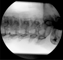
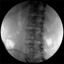
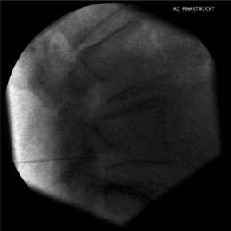
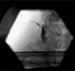
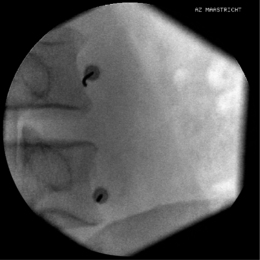
Again, this technique is performed without any sedation because of the need of cooperation of the patient. The radiofrequency lesioning of the dorsal root ganglion (RF-DRG) is only performed after a positive diagnostic segmental nerve block (usually several diagnostic blocks are performed). For this procedure, the patient is lying supine on the operating table with a slight extension of the neck. Firstly, the C-arm should be positioned obliquely so that the first three contralateral pedicles are projecting just posteriorly to the anterior line of the vertebral bodies. Secondly, the intervertebral discs should be clearly visible. To do so, the C-arm is orientated in the frontal plane. One should adapt C-arm positioning to have an optimal view of the intervertebral foramen of the level one wants to treat. The axis of the intervertebral foramen points 25–35° anteriorly and 10° caudally. The inclination of the C-arm in the frontal plane should be such that there is no double contour in the caudal aspect of the foramen. Then the target point is identified: it is posterior in the neuroforamen between the caudal and the middle third. This dorsal position is chosen in order to avoid possible damage to the motor fibers of the segmental nerve and to the vertebral artery, which runs anterior to the ventral part of the foramen. The entry point is marked on the skin and is the same as the target point. This technique is a ‘tunnel vision’ technique what means that the entry of the needle is in the direction of the X-rays.32 The needle is than projected on the screen like a dot and the field of vision can theoretically be narrowed down to a tunnel-like diameter (Fig. 24.4). After injection of local anesthetic (lidocaine 1%) into the skin with a 22-gauge subcutaneous needle, a 22-gauge spinal needle or, preferably, a needle with a connecting tube is inserted into the superficial layers of the skin, in the direction of the X-rays so that the electrode is projected on the screen as a dot. Subsequently, the needle is advanced carefully and every step is checked with fluoroscopy. There is the possibility of inadvertent puncture of the segmental nerve. That is why an early check in the anteroposterior (AP) view is done. In this view, the endpoint is the point where the tip of the needle is projecting 1–2 mm lateral to the lateral border of the facet column. Thereafter, only 0.2–0.5 mL of water-soluble dye (Iohexol 240 mg/mL; Omnipaque® 240) is injected to confirm the proper position of the needle tip close to the segmental nerve and to exclude an accidental intradural or intravascular position of the electrode. When this is confirmed, 0.5 mL of local anesthetic (lidocaine 1–2%) is injected. Alternatively, to perform a radiofrequency lesion, the cannula is advanced until the tip projects into the middle of the facet column (Fig. 24.5). Then the stylet is removed and 0.2–0.5 mL of dye is injected to confirm proximity to the targeted nerve root. The RF probe is now inserted through the cannula. After checking the impedance, electrical stimulation is started at a rate of 50 Hz. The patient should feel a tingling sensation. If the stimulation threshold is felt under 0.4 volts, the needle is withdrawn until the threshold is between >0.4 and <0.65 volts. At the C2 level, a suboccipital tingling has to be confirmed by the patient. Next, the frequency is changed to 2 Hz, and the patient is observed for muscle contractions in the arm and/or hand. These should not occur below a voltage of 1.5 times the 50 Hz threshold. When the thresholds are acceptable, 0.5–1.0 mL of local anesthetic (lidocaine 1–2%) is injected. Subsequently, an RF current is led through the electrode in order to increase the temperature at the tip slowly to 67°C for 60 seconds. As mentioned above, there is the tendency toward using pulsed RF current when treating the DRG because it is believed to be less destructive. With this technique, the stimulation at 50 Hz is started when the needle tip is projecting 2 mm medially to the lateral border of the facet column. An ideal threshold is obtained at <0.3 Hz. Then, a conventional 2 × 20 msec/sec, 45 volt and 120 sec. pulsed RF procedure is performed. The pulsed RF treatment can be repeated a second time if the 50 Hz threshold is lower than the initial threshold after a slight repositioning of the needle.
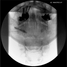
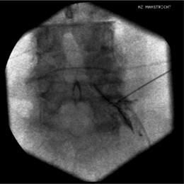
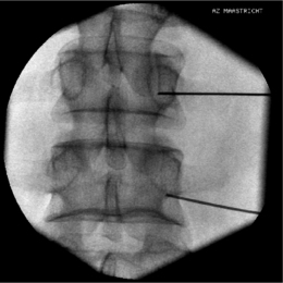
To perform a diagnostic block and (pulsed) RF procedure of the C2 DRG, the C-arm is positioned straight lateral because of the different anatomy at this level. There is no facet joint and there are no major blood vessels in the direct neighborhood that should be considered. The target point of the DRG of C2 is about 3 mm posterior to the tip of the dome-shaped space between the laminae of the C1 and C2 vertebrae (Fig. 24.6). After injection of a local anesthetic, the needle is inserted and advanced in a tunnel vision technique. The depth of the needle is checked in the AP position (Fig. 24.7) and the needle tip should be projecting halfway across and posterior to the C1–2 joint using a through-the-mouth view. The next steps are identical to those described above for the C3 to C7 DRG.
Postprocedure care
The patient can be discharged 1–2 hours postprocedure. Driving or operating dangerous machinery during the first 24 hours after the procedure is prohibited. A side effect that is often seen (40–60%) is a mild burning sensation (some deep neck soreness) in the treated dermatome that subsides spontaneously after 1–3 weeks.33 Some sensory changes, such as a slight hypoesthesia, may occur but invariably disappears within 3–4 months.34,35
RADIOFREQUENCY DENERVATION IN THE THORACIC REGION
Thoracic percutaneous radiofrequency denervation of the facet joints
Relevant anatomy
In contrast to the lumbar facet joints, the thoracic facet joints are more vertically oriented and almost parallel to the coronal plane (Fig. 24.8). They are oriented perpendicular to the sagittal plane and face directly anterior. The thoracic facet joints are innervated by medial branches of the posterior primary rami of the segmental nerves. Each thoracic facet joint is bisegmentally innervated by the medial branch of the same level and the medial branch of the level above. The thoracic medial branches pass through the intertransverse space and touch the superolateral corner of the transverse process. Then they run medially and inferiorly across posterior surfaces of the transverse processes before entering the posterior compartment of the back and innervating the multifidus muscles.36 In that location they give ascending articular branches to the facet joint. An exception to this pattern occurs at the midthoracic levels (T5–8). Although the curved course remains essentially the same, inflection occurs at a point superior to the superolateral corner of the transverse process. This course is different than that seen with the lumbar medial branches which are fixed at the junction of the superior articular process and the transverse process.37 The T11 and T12 medial branches have the same course as the lumbar medial branches.37 Obtaining a fluoroscopic view is quite difficult for a variety of reasons. In this region one has to contend with overprojection of the ribs, the prominent transverse process that is directed slightly cranial and markedly posterior, and the size and orientation of the pedicles that can make them difficult to visualize. In addition, the orientation of the thoracic facet joints impedes the operator’s ability to differentiate between superior and inferior articular process.
Procedure
Sedation is avoided as communication between operator and patient must be maintained at all times. In contrast to diagnostic thoracic intra-articular block, which has been well described,38 expert opinion varies on RF lesioning of median branches in the thoracic vertebrae. Nonetheless, the authors describe how they perform an RF lesion of the median branches at the thoracic level. Although the authors embrace this technique some authors have suggested that the needle tip is actually ‘too far anterior’ to the medial branch to result in denervation. The authors use the junction between the superior articular process and the superior border of the transverse process as a target point for thoracic medial branch neurotomy, Stolker et al. reported that with this target site the medial branch of the dorsal ramus was never within reach of the electrodes.39 Based on Stolker’s work, the authors suggest exercising caution regarding categorical acceptance of the technique described here.
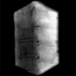
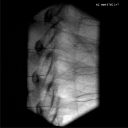
The C-arm is positioned in the transverse plane and an external radiopaque object such as a clamp is used to identify the proper level. A straight-on AP view of the vertebra at the anticipated target level is obtained. The endplates of the vertebra should be parallel without any visible endplate double contours. Then the C-arm is axially and slightly obliquely rotated in the sagittal plane. This should facilitate the access to the target point that is the junction of the superior articular process and the transverse process. A proposed entry point is marked on the skin and local anesthetics (lidocaine 1%) with a 23-gauge needle are injected. The RF needle is then inserted parallel with the gantry angle (angle of the C-arm beam) until bone contact is reached at the junction of the superior articular process and the transverse process (Fig. 24.9). Subsequently, the needle is redirected slightly more cranially and laterally until it is just loses osseous contact. Then the needle position is checked in the lateral view. The needle tip should be just posterior to a line connecting the posterior aspects of the neuroforamina (Fig. 24.10). Stimulation at 50 Hz is now performed. A paravertebral tingling sensation should be perceived with a current with a voltage of less than 0.5 volts. Next, stimulation at 2 Hz should provoke paravertebral muscle contractions at a voltage of ≤1. Stimulation should be negative for anterior nerve root stimulation, which would be perceived as muscle contraction and/or pain in the anterior chest wall or abdominal region depending on the level undergoing RF. When proper needle positioning has been confirmed with fluoroscopic imaging and electrical stimulation, 0.5 mL of lidocaine 1–2% is administered at each level. After local anesthesia has taken effect, RF lesioning is conducted for 60 sec at 20 V. The authors typically RF three levels because of the multisegmental innervation of the facet joints.
As was alluded to earlier, the authors use this technique and are attempting to refine it.
Thoracic radiofrequency lesioning of the dorsal root ganglion
Procedure
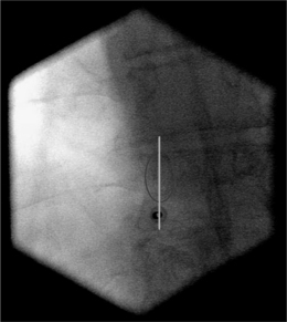
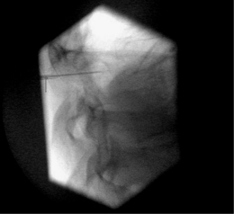
Two or more diagnostic blocks at different levels must be performed to identify the segment involved, because of the frequent overlapping of thoracic segmental pain from one segment to another. An intercostal block can be used as a test block of a thoracic segmental nerve.40 The level which provides the best temporary pain reduction is then selected for RF lesioning of the dorsal root ganglion. As described above, in the upper thoracic spine, the classic approach (posterolateral) is not possible because the foraminae face more anteriorly and accurate positioning of the needle is hindered by the angle of the ribs. Therefore, an alternative technique is used to reach the DRG of T7 and above. The patient is placed in a prone position and a dorsal approach is used. The target point is the craniodorsal part of the intervertebral foramen and is thus the same as the target point in the classic dorsolateral approach. The entry point is the midpoint of the pedicle in the posteroanterior view (Fig. 24.11). This entry point is checked in a lateral view where it should aim for the superior dorsal quadrant of the foramina where the DRG should be situated. A small hole is drilled through the lamina of the vertebra under fluoroscopic guidance in the posteroanterior view using a 16-gauge Kirschner wire and local anesthesia. A potential danger is the piercing of the facet joint. Then, an RF cannula is inserted through the burr hole into the proper position, which is checked in the lateral view and should be in the craniodorsal part of the intervertebral foramen (Fig. 24.12). The stylet of the cannula is replaced with an RF probe and stimulation at 50 Hz is carried out. The patient should feel tingling sensations in the selected dermatome using a 0.4–1.0 V stimulus. Stimulation at 2 Hz should not give contractions of the intercostal muscles at a stimulation threshold below 1.5 times the sensory threshold. After satisfactory placement is achieved, 0.4 mL of contrast medium (Omnipaque) is injected to exclude intradural or intravascular spread. When correct position has been confirmed, 1–2 mL of lidocaine 1–2% is injected and a 60 second, 67°C lesion is made. One could consider performing PRF lesioning (pulses of 2 Hz and 20 msec during 120 seconds), but this technique has not yet been proven to be less destructive or as effective as RF lesioning.
RADIOFREQUENCY DENERVATION IN THE LUMBAR REGION
Lumbar percutaneous radiofrequency denervation of the facet joints
Relevant anatomy
The lumbar facet joints are all almost vertically oriented (Fig. 24.13). The upper lumbar facet joints are more oriented in the sagittal plane and they rotate to a more oblique angle in the lower lumbar region. The upper facet joints are more curved than the lower joints, which are more flat. The facet joint is innervated by the medial branch of the posterior ramus of the spinal nerve. As it exits from the intervertebral foramen, the spinal nerve divides into an anterior primary ramus and a posterior primary ramus. At approximately 5 mm from its origin, the posterior primary ramus divides into medial, lateral, and intermediate branches. The medial branch supplies the facet joint at its own level and the next lower level. The medial branch runs in a dorsal and caudal direction and lies in a groove on the base of the superior articular process in direct contact with the base of the superior surface of the transverse process. Each medial branch also supplies the multifidius, interspinales, and intertransversarii mediales muscles and the ligaments and periosteum of the neural arch.
Procedure
The patient assumes a prone position on the fluoroscopic table. A pillow is placed under the abdomen to diminish the physiological lumbar lordosis. Firstly, targeted levels are identified and a straight AP projection is obtained. Then, the C-arm is axially rotated until there are no visible double contours of the caudal endplate of the middle vertebra. The middle vertebra of the levels to be treated is used as the reference point prior to the searching for the optimal position of the C-arm. Subsequently, the C-arm is rotated to an approximately 15° oblique view until the spinous processes are projecting off the midline but well inside the contralateral facet joints. Then, the entry point should be marked over the target point, which is the point at the junction of the superior articular process and transverse process. To perform a diagnostic block, the target point should be approximately 1 mm under this junction to avoid inadvertent spread of local anesthetic to segmental nerves, thereby creating the potential for a false-positive result. After injection of local anesthetic (lidocaine 1%) into the skin, the needle is inserted at the entry point and slowly advanced using a tunnel vision technique until the tip makes osseous contact. For a diagnostic block, the position of the needle is then checked in the lateral view, which should be at the level of the inferior part of the intervertebral foramen in line with the facet joint column. When accurate positioning is confirmed and following a negative aspiration, 1 mL of local anesthetic (lidocaine 1%) is injected at each level. To perform an RF lesioning of the medial branch, after making bone contact with the needle tip, the needle is redirected slightly more cephaled until bone contact is lost and immediately the target point is reached (Fig. 24.14). Then, the C-arm is rotated into the lateral view to check the position of the needle tip, which should be in line with the facet joint column and at the level of the inferior part of the intervertebral foramen about 1 mm dorsal to the level of the line connecting the posterior aspects of the intervertebral foramina (Fig. 24.15). It should be a little deeper and more cranial than the position of the needle for the diagnostic block. When this position is confirmed, the impedance is checked and, if acceptable, stimulation at 50 Hz is conducted. The patient should feel new pressure or tingling in the back at a voltage of <0.5 V. If sensations are felt in the ipsilateral extremity, the needle tip is too close to the segmental nerve. It is imperative the needle be slightly withdrawn and stimulation at 50 Hz checked again. Subsequently, settings are changed so that stimulation occurs at 2 Hz. The patient should experience localized contractions of the multifidus muscle and not of muscles of the leg. These local contractions can be palpated by the operator. Similarly, any contractions that occur in the leg may be detected by the operator or the assistant if a hand is placed over the muscles innervated by the exiting nerve root. If the patient perceives pain and/or contractions in the extremity or if muscular contractions are detected by an operator then the needle must be repositioned. After accurate positioning of the needle tip is attained and a negative aspiration is demonstrated, 1 mL of local anesthetic (lidocaine 1%) is injected at each level. RF lesioning of 20 V (approximately 67°C) is performed for 60 seconds.
The fluoroscopic view for the L5–S1 facet joint and thus the median branch of the L5 is different from the other lumbar levels because of the difference in anatomy. The L5 medial branch lies at the junction between the superior sacral articular process and the upper border of the sacrum. Since there is no pedicle at this level to use as a radiological landmark, the C-arm is positioned so that the junction is seen as a round, curved transition. The C-arm is rotated slightly obliquely (about 15°). The identified target point is the curve of the transition and is the same as the entry point. The needle is thus placed in tunnel vision (Fig. 24.16). The depth of the needle is checked in the lateral position and the tip must project over the posterior border of the facetal column. Thereafter, the rest of the procedure is the same as described before.
Equipment
A 22-gauge, 10 cm SMK needle with a 5 mm active tip can be used to perform an RF lesioning. Another possibility is to use a 10 cm, 20-gauge blunt RFTC needle with a 10 mm active tip and a 16-gauge angiocatheter as an introducer. However, no clinical studies have been published using the latter mentioned equipment.
Postprocedure care
The patient is allowed to go home immediately after the procedure. Driving a car or handling dangerous machinery is proscribed for the first 24 hours. In some instances there will be a transient numbness of the ipsilateral extremity because of overflow of local anesthetics into the intervertebral foramen. The overall incidence of minor complications per radiofrequency site was found to be only 1%.41 For up to 2 weeks after the procedure there may be burning pain perceived in the lower extremity (neuritic pain) or there can be more localized pain lasting in excess of 2 weeks. Invariably, these are short-lived side effects and will resolve spontaneously. Other possible side effects include infection, bruising, and muscle spasms.
Lumbar radiofrequency lesioning of the dorsal root ganglion
Procedure
Sedation is not employed. The procedure is performed with the patient in prone position on a fluoroscopic table with a pillow under the abdomen to diminish the physiological lumbar lordosis and facilitate the approach. A straight AP view is secured and the targeted segmental level is identified using a radiopaque object such as a clamp. Then, the C-arm is axially rotated to give a view of the targeted vertebra without any double contour of the endplate. Subsequently, the C-arm is rotated obliquely, approximately 20–25°, so that the spinous processes are projecting just medially to the contralateral facet column. Then, the entry point is marked and is the same as the target point (Fig. 24.17). The target point is different for a diagnostic segmental block in comparison to an RF of the DRG. For a diagnostic block, the target point is 1–2 cm distal to the DRG. The target point for an RF lesioning of the DRG is approximately 1 mm caudad to an imaginary line that bisects the pedicle. After infiltration of the skin with local anesthetics (lidocaine 1%), the needle is inserted and slowly advanced using a tunnel vision technique. The depth of the needle should be checked following each advancement. This is best viewed using a lateral projection. If this is not done, the root can be inadvertently irritated or even injured. In this lateral view, the needle tip should rest within the cranial part of the intervertebral foramen and only 1 mm past the posterior aspect of this foramen (Fig. 24.18). To do a diagnostic block of the segmental nerve, which is always performed before any RF lesioning, the needle should also be in the cranial part of the intervertebral foramen, but at the ventral border. Even using meticulous technique does not guarantee that the root will not be touched by an advancing needle. The authors routinely warn the patient that this may happen and that they should not be concerned. If the patient experiences a sudden jolt of pain in the ipsilateral radicular dermatome the needle should be immediately withdrawn a millimeter or two. The next step is to check the needle position by injecting contrast medium. Turn the C-arm in an AP projection, where the needle tip should be projecting within the contours of the vertebra and inject a small volume of dye. Only the exiting nerve should be seen and there should be no flow of contrast into the epidural space (Fig. 24.19). For a diagnostic block, more than 1 mL of local anesthetic (lidocaine 1%) is injected. To perform an RF or PRF lesioning of the DRG, stimulation at 50 Hz is first conducted. It should give a tingling sensation in the leg in the appropriate dermatome at a threshold <0.5 V. Subsequently, the 2 Hz threshold is searched for and should occur at less than 150% of the previously established 50 Hz threshold. In the lumbar region, the PRF lesioning of the DRG is preferred as it may be less destructive than RF lesioning. The authors create a lesion over 120 seconds using pulses of 2 × 20 msec/sec at 45 V. If the impedance is >400 Ohms, 1 mL of lidocaine 1% should be injected before the lesioning. The tip temperature should not exceed 42°C. If this occurs, the voltage should be lowered to 40°C.
Prior to performing this intervention, the spine clinician should be aware that there is level two evidence that RF lesioning of a lumbar DRG is not effective.42
THE SYMPATHETIC SYSTEM
Stellate ganglion block
Relevant anatomy
The cervical paravertebral sympathetic trunks consists of preganglionic fibers originating in the anterolateral horn of the first and second thoracic spine segments (Fig. 24.20). They innervate the head and the neck. These preganglionic fibers travel with the ventral roots of T1 and T2 as white communicating rami and then join the sympathetic chain cephalad and synapses either at the inferior or middle or superior cervical ganglion. The inferior cervical ganglion is called the stellate ganglion and all preganglionic fibers either synapse here or pass through this ganglion. Then the postganglionic fibers run cranially following a course along the carotid arteries or go to the cervical plexus or upper cervical nerves as gray communicating rami to innervate neck structures.
Often, the inferior cervical ganglion and the upper thoracic ganglion are fused to form the stellate ganglion. Sometimes the middle cervical ganglion is also fused with the stellate ganglion. The stellate ganglion usually lies on the lateral border of the longus colli muscle anterior in the neck between the base of the seventh cervical transverse process and the first rib. The classic approach to block the stellate ganglion is at the C6 level, namely at the Chaussignac’s tubercle. The ganglion is limited medially by the longus colli muscle, laterally by the scalene muscles, inferiorly by the pleura, anteriorly by the subclavian artery, and posteriorly by the transverse processes.43
Procedure
The use of the C-arm is optional, but practical to check and confirm proper needle positioning.
The anterior approach at C6 is the most commonly used approach, but it can give an insufficient block of the sympathetic innervation of the upper extremity (see above). The patient is lying supine on a fluoroscopic table with a pillow under the shoulders to slightly hyperextend the neck. In this manner, the landmarks are easier to locate and the esophagus on the left side will be located more medially and thus away from the needle insertion point. The target point is the same as the entry point and is the Chaussignacs’ tubercle (C6) approximately 1–2 cm from the midline. This tubercle can be palpated and is located at the medial border of the sternocleidomastoid muscle lateral to the cricoid cartilage. Palpation of the tubercle is best done with the index finger, and most of the time this finger is also used to retract the carotid artery laterally away from the needle entry point. Then the needle is inserted just medially to the index finger towards the junction between the tubercle and the C6 vertebral body. Local injection of the skin is done with lidocaine 1%. The needle is aimed downwards perpendicular to the fluoroscopic table until bone contact is made. This bony contact is expected at a depth of 2.0–2.5 cm. Pneumothorax can be avoided with careful placement of the needle: control the direction and advance the needle gradually. The needle position can then be checked with fluoroscopy in the anteroposterior position (Fig. 24.21) and in the lateral view after injection of water-soluble dye. Of course, this injection of dye is only performed when the aspiration test has proven to be negative: i.e. no aspiration of cerebrospinal fluid or blood. When proper needle position is confirmed following the spread of the contrast medium, local anesthetic (lidocaine 1%) can be injected gradually using 0.5 mL as a test injection. After every 3–4 mL of local anesthetic, careful re-aspiration should be done to exclude dislocation of the needle point. At least 5 mL of local anesthetic fluid is needed to block the stellate ganglion, but this volume does not guarantee that Kuntz’s nerves (T2 and T3) will be blocked. A volume of at least 10 mL is probably needed to block all the sympathetic innervation of the upper extremity including the anomalous Kuntz’s nerves.
Equipment
To perform a stellate ganglion block, a 23- or 24-gauge 4–6-cm needle can be used. A side line tubing is recommended because it guarantees the stability of the needle tip during the aspiration and the injection (for example: a 60 mm 24-gauge Pole RC needle). A 22-gauge SMK needle of 50 mm with a 4 mm active tip can be used to perform a radiofrequency thermolesion.
Thoracic sympathetic block
Relevant anatomy
The preganglionic fibers of the thoracic sympathetic chain originate from the anterolateral horn of the respective thoracic spine segments and travel with the thoracic segmental nerves through the intervertebral foramen.44 As white communicating rami, they synapse with postganglionic fibers in the thoracic sympathetic ganglia. Most often, there are 10 pairs of thoracic sympathetic ganglia lying paravertebrally and at the posterolateral surface of the thoracic vertebral bodies. Sometimes 11 pairs of ganglia can be found. Some of the postganglionic fibers return to their respective somatic nerves as gray communicating rami and go to the regional vasculature, the sweat glands, and the pilomotor muscles of the skin. Some of them go to the cardiac plexus and go up or down the sympathetic trunk to end in more distant ganglia. As mentioned above, the first thoracic ganglion is fused with the lower cervical ganglion to form the stellate ganglion.
Equipment
A 23- or 24-gauge, 4–6 cm needle can be used (for example: a 60 mm 24-gauge Pole RC needle).
Lumbar sympathetic block
Relevant anatomy
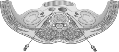
The lumbar sympathetic chain consists of two paravertebral trunks that are connected segmentally by preganglionic neurons (Fig. 24.22). These preganglionic fibers follow their corresponding nerves as white communicating rami and communicate in the paravertebral ganglia with postganglionic efferents and with efferents to the pelvic viscera. Some postganglionic fibers directly pass the ganglia and go to the ganglia in the aortic plexus and the superior and inferior hypogastric plexuses. The postganglionic fibers leave the sympathetic chain as gray communicating rami. Some go to the L1 nerve (iliohypogastric and genitofemoral nerve), others go to the L2–5 nerves, and the rest go to the upper three sacral nerves and end in the lumbosacral plexus.
Procedure
Sedation should not be employed.
The patient lies in a prone position on a radioscopic table. A straight AP projection is obtained. Next, the obliqueness is adjusted. The spinous processes should project over the contralateral facet column, which is usually at about a 35° oblique angle. The target point is approximately 1 mm lateral to and a little caudal to the middle of the concavity of the vertebral body (Fig. 24.23). This point is often obstructed by the transverse process. Therefore, the C-arm is rotated axially to move the transverse process upwards so that visualization of the target point is unobstructed. After local infiltration of the skin with lidocaine 1%, the needle is inserted and advanced using a tunnel vision technique. The depth is checked on the lateral view. The needle tip should be at the anterior border of the vertebra (Fig. 24.24). In the AP view, the needle tip should be projecting within the lateral border of the vertebra and over the facet column (see Fig. 24.24). During the procedure, the patient is asked to report paresthesias, especially when the L4 level is treated, because of the possibility of making contact with the L3 ramus and thus the genitofemoral nerve. When the needle is in the right position, 1–2 mL of water-soluble contrast medium is injected and should spread cranially and caudally. A lateral spread of the dye at the L4 level suggests dispersal within the psoas muscle. When this happens, the needle should be redirected more anteriorly or medially. In the lateral view, the dye should spread at the anterolateral border of the vertebra in a linear fashion (Fig. 24.25). For an RF lesion, the next step is to perform sensory stimulation at 50 Hz. The patient should only feel a little pressure or warmth in the back, but not in the inguinal region or groin because this suggests the proximity of the needle tip to the genitofemoral nerve. Using motor stimulation of up to 2 or 3 volts should not trigger fasciculations or induce inguinal or groin pain. When the correct position is confirmed and a negative aspiration obtained, then 1–2 mL of local anesthetic (lidocaine 1%) is injected and an RF lesion (90 seconds, 67°C) is performed.
1 Kirschner M. Zur Electrochirurgie. Arch Klin Chir. 1931;161:761.
2 Mullan S, Hekmatpanah J, Dobbin G. Percutaneous intramedullary cordotomy utilizing the unipolar anodal electrolytic lesion. J Neurosurg. 1965;22:548-553.
3 Rosomoff H, Carroll F, Brown J. Percutaneous radiofrequency cervical cordotomy technique. J Neurosurg. 1965;23:639-644.
4 Sweet WH, Wepsic JG. Controlled thermocoagulation of trigeminal ganglion and rootlets for differential destruction of pain fibers. 1. Trigeminal neuralgia. J Neurosurg. 1974;40(2):143-156.
5 Shealy CN. Percutaneous radiofrequency denervation of spinal facets. Treatment for chronic back pain and sciatica. J Neurosurg. 1975;43(4):448-451.
6 Sluijter ME, Koetsveld Baart CC. Interruption of pain pathways in the treatment of the cervical syndrome. Anaesthesia. 1980;35(3):302-307.
7 Sluijter ME. The use of radiofrequency lesions for pain relief in failed back patients. International Disability Studies. 1988;10(1):37-43.
8 Stolker RJ, Vervest AC, Groen GJ. Percutaneous facet denervation in chronic thoracic spinal pain. Acta Neurochirurgica. 1993;122(1–2):82-90.
9 Sluijter M, Mehta M. Treatment of chronic back and neck pain by percutaneous thermo-lesions. In: Lipton S, Miles J, editors. Persistent pain, modern methods of treatment. London: Academic Press; 1981:141-179.
10 van Kleef M, Spaans F, Dingemans W, et al. Effects and side effects of a percutaneous thermal lesion of the dorsal root ganglion in patients with cervical pain syndrome. Pain. 1993;52(1):49-53.
11 Sluijter M, Cosman E, Rittman W. The effects of pulsed radiofrequency fields applied to the dorsal root ganglion – a preliminary report. Pain Clin. 1998;11(2):109-117.
12 Wedley J, Gauci C. Radiofrequency. Handbook in clinical techniques in the management of chronical pain. Switzerland: Howard Academic, 1994.
13 Cosman ER, Nashold BS, Ovelman Levitt J. Theoretical aspects of radiofrequency lesions in the dorsal root entry zone. Neurosurgery. 1984;15(6):945-950.
14 Bogduk N, Macintosh J, Marsland A. Technical limitations to the efficacy of radiofrequency neurotomy for spinal pain. Neurosurgery. 1987;20(4):529-535.
15 Moringlane JR, Koch R, Schafer H, et al. Experimental radiofrequency (RF) coagulation with computer-based on-line monitoring of temperature and power. Acta Neurochirurgica. 1989;96(3-4):126-131.
16 Vinas S, Zamorrao L, Duiouny M. In vivo and in vitro study of the lesions produced with the computerised radiofrequency system. Sterotact Funct Neurosurg. 1992;58:121-133.
17 Sluijter M, Van Kleef M. Factors governing the size of radiofrequency lesions – description of a computer model. 1st scientific meeting of the European Federation of IASP chapters. Verona: Pain in Europe, 1995.
18 Letcher FS, Goldring S. The effect of radiofrequency current and heat on peripheral nerve action potential in the cat. J Neurosurg. 1968;29(1):42-47.
19 Uematsu S. Percutaneous electrothermocoagulation of spinal nerve trunk, ganglion and rootlets. In: Schmidel HH, editor. Current technique in operative neurosurgery. New York: Grune and Stratton; 1977:469-490.
20 Smith HP, McWhorter JM, Challa VR. Radiofrequency neurolysis in a clinical model. Neuropathological correlation. J Neurosurg. 1981;55(2):246-253.
21 de Louw AJ, Vles HS, Freling G, et al. The morphological effects of a radiofrequency lesion adjacent to the dorsal root ganglion (RF-DRG) – an experimental study in the goat. Eur J Pain. 2001;5(2):169-174.
22 Higuchi Y, Nashold BSJr, Sluijter M, et al. Exposure of the dorsal root ganglion in rats to pulsed radiofrequency currents activates dorsal horn lamina I and II neurons. Neurosurgery. 2002;50(4):850-855.
23 Sluijter M, Van Kleef M. Characteristics and mode of action of radiofrequency lesions. Cur Rev Pain. 1998;2:143-150.
24 Cahana A, Vutskits L, Muller D. Acute differential modulation of synaptic transmission and cell survival during exposure to pulsed and continuous radiofrequency energy. J Pain. 2003;4(4):197-202.
25 Sluijter M. The medial branch procedure. In: Sluijter M, editor. Radiofrequency. Part 2: thoracic and cervical region, headache and facial pain. Meggen (Switzerland): FlivoPress SA; 2003:99-110.
26 Van Kleef M, Sluijter M. Radiofrequency lesions in the treatment of pain of spinal origin. In: Gildenberg P, Tasker R, editors. Textbook of stereotactic and functional neurosurgery. New York: The McGraw-Hill; 1998:1585-1599.
27 van Suijlekom HA, van Kleef M, Barendse GA, et al. Radiofrequency cervical zyga-pophyseal joint neurotomy for cervicogenic headache: a prospective study of 15 patients. Funct Neurol. 1998;13(4):297-303.
28 Lord SM, Barnsley L, Bogduk N. The utility of comparative local anesthetic blocks versus placebo-controlled blocks for the diagnosis of cervical zygapophyseal joint pain. Clin J Pain. 1995;11(3):208-213.
29 Buijs E, van Wijk R, Geurts W, et al. RF lumbar facet denervation: a comparative study of the reproducibility of lesion size after 2 current radiofrequency techniques. Reg Anesth Pain Med. 2004;29(5):400-407.
30 Bogduk N, Marsland A. The cervical zygapophyseal joints as a source of neck pain. Spine. 1988;13(6):610-617.
31 Vervest A, Stolker R. The treatment of cervical pain syndromes with radiofrequency procedures. Pain Clin. 1991;4:103-112.
32 Sluijter M. Principles of procedures. (Chapter 5). In: Sluijter M, editor. Radio-frequency. Part 1: A review of radiofrequency procedures in the lumbar region. Meggen (Switzerland): Flivo Press SA; 2001:89-104.
33 van Kleef M, Liem L, Lousberg R, et al. Radiofrequency lesion adjacent to the dorsal root ganglion for cervicobrachial pain: a prospective double blind randomized study. Neurosurgery. 1996;38(6):1127-1131.
34 Slappendel R, Crul BJ, Braak GJ, et al. The efficacy of radiofrequency lesioning of the cervical spinal dorsal root ganglion in a double blinded randomized study: no difference between 40 degrees C and 67 degrees C treatments. Pain. 1997;73(2):159-163.
35 van Zundert J, Lamé I, de Louw A, et al. Percutaneous pulsed radiofrequency treatment of the cervical dorsal root. Ganglion in the treatment of chronic cervical pain syndromes: a clinical audit. Neuromodulation. 2003;6(1):6-14.
36 Chua W, Bogduk N. The surgical anatomy of thoracic facet denervation. Acta Neurochirurgica. 1995;136:140-144.
37 Bogduk N, Long DM. The anatomy of the so-called ‘articular nerves’ and their relationship to facet denervation in the treatment of low-back pain. J Neurosurg. 1979;51(2):172-177.
38 Gray D, Bajwa Z, Warfield C. Facet block and neurolysis. In: Waldman SLR, Ross A, et al, editors. Interventional pain management. Philadelphia: WB Saunders; 2001:446-483.
39 Stolker R, Vervest A, Groen GJ. Electrode positioning in the thoracic percutaneous partial rhizotomy: an anatomical study. Pain. 1994;57:241-251.
40 Dooley JF, McBroom RJ, Taguchi T, et al. Nerve root infiltration in the diagnosis of radicular pain. Spine. 1988;13(1):79-83.
41 Kornick G, Kramarich S, Lamer T, et al. Complications of lumbar facet radiofrequency denervation. Spine. 2004;29(12):1352-1354.
42 Geurts JW, van Wijk RM, Wynne HJ, et al. Radiofrequency lesioning of dorsal root ganglia for chronic lumbosacral radicular pain: a randomised, double-blind, controlled trial. Lancet. 2003;361(9351):21-26.
43 Moore D. Stellate ganglion block. Springfield, IL: 1954.
44 Pitkin G. Cervical and thoracic nerves. Philadelphia: JB Lippincott, 1946.
45 Rai P, Rauck R, Racz G. Autonomic nerve blocks. St. Louis: Mosby-Year Book, 1996.
[/level-membership-for-physical-medicine-and-rehabilitation-category][not-level-membership-for-physical-medicine-and-rehabilitation-category]
CHAPTER 24 Technique of Radiofrequency Denervation
INTRODUCTION
History
The use of electrical current to create lesions for the treatment of pain began in 1931, when Kirschner introduced it for the treatment of trigeminal neuralgia.1 In 1965, Mullan used direct current to perform percutaneous lateral cordotomy for unilateral malignant pain.2 Later that year, Rosomoff modified this technique and used radiofrequency (RF) current for this treatment.3 An RF current was found to produce more predictable, circumscribing lesions. Several years later, Sweet and Wepsic described their technique for the use of RF lesions of the Gasserian ganglion in the treatment of trigeminal neuralgia.4 In spinal pain, the use of RF current was reported in a series of cases by Shealy (1975).5 He described RF lesioning of the medial branch to treat lumbar facet joint pain. Subsequently, more options for the use of RF lesioning in various spinal pain syndromes were introduced into clinical practice.6–8 The introduction of a small-diameter (22-gauge) temperature monitoring electrode system by Sluijter and Mehta in 19819 increased the safety of the current method used.10 Since then, RF procedures have been widely adopted by many pain practitioners. In addition there have been many new technical developments, such as the improvement of the quality of C-arm image intensifiers. All these developments have contributed to a widespread use of RF lesioning.
Recently, a modification of the traditional RF method was introduced by Sluijter et al.11 They used the same output setting of the lesion generator that was used for making heat lesions as in RF lesioning, but they interrupted this output to allow generated heat to be washed out by thermal conductivity and circulation. This technique is called ‘pulsed radiofrequency’ (PRF) and is claimed to be nondestructive. Until now, there are no reports of any sensory or motor loss following this procedure. However, it is too soon to categorically recommend this technique because the mechanism of action is still unknown. Until several double-blind, randomized, controlled trials are conducted this new approach should not be routinely employed.
Physics
Radiofrequency current
An RF current is applied by an RF lesion generator through an electrode, which is insulated except for the most distal part. This exposed region is the active portion of the electrode. The RF current flows from the electrode tip to the dispersive ground plate, which is placed on the arm or leg of the patient and leads the current back to the RF lesion generator. RF current flows through tissue and results in an electric field. This electric field places an electric force on the ions within tissue electrolytes, causing them to oscillate at a high rate (i.e. 300 000 times per second).12 Tissue heating is created by frictional dissipation of the ionic current within the fluid medium, which heats the electrode.
Lesion size
The size of the lesion not only depends on the diameter of electrode and the length of the uninsulated electrode tip, but also depends on tip temperature. This was confirmed in animal studies by Cosman et al. in 1984.13 Bogduk et al. studied not only the size of the lesions, but also the shape of the lesion.14 They performed experimental lesions in egg white and fresh meat. They found that RF lesions do not extend distal to the tip of the electrode, but extend radially around the active electrode tip in a spheroidal shape. Based on these observations, Bogduk suggested that the best placement of the electrode tip was parallel to the target structure.
Other research methods involving computerized or mathematical modeling of similar experiments have been used. For example, Moringlane et al. studied experimental RF coagulation with a computer-based on-line monitoring of temperature and power.15 Vinas et al. also studied lesion size in vivo using fresh eggs and in vitro using the subcortical white matter of rabbits.16 Both investigators obtained results that were similar to those reported by Bogduk et al. Once equilibrium temperature is reached (after 20–40 seconds), the size of the lesion does not increase. However, some variables such as circulation effect and the tissue heat conductivity may also produce a variation in lesion size, but are unpredictable.13 Consequently, the lesion size may therefore be variable at different locations within the body.
Radiofrequency lesion generator
The modern RF lesion generating system has different functions, including a pulsed RF mode. There is continuous on-line impedance measurement to confirm continuity of the electrical circuit and to detect any short circuits. One of the key components of the system is nerve stimulator function. It is used to confirm the proper position of electrode tip (it indicates the electrode-to-nerve distance) and to permit minor adjustments. To ensure the proximity of the active tip to the sensory fibers, stimulation is performed at 50 Hz. The 2 Hz stimulation is carried out to detect extraspinal muscle contractions that occur when the needle is placed too close to a nerve root motor fiber. Voltage, current, and wattage during an RF procedure are also monitored. Finally, a generator monitors temperature using a thermocouple. This is an important lesion parameter, but the temperature is only measured at the tip of the electrode and not in the more peripheral zones of the lesion area. The usefulness of tip temperature to monitor the lesion size is minimized because the lesion size is dependent on local blood circulation. There is a rapid drop in temperature over the first few millimeters from the electrode tip.13,17
Effect of radiofrequency current on nerve tissue
The effect of RF lesions on nerve tissue is controversial. Letcher and Goldring, in 1968, investigated the effect of RF current and heat on the nerve action potential of the saphenous nerve in cats.18 Delta and C-fibers were blocked before the alpha-beta group by both RF current and heat. Uematsu,19 and subsequently Smith et al.,20 reported quite disparate results. Smith et al. created RF lesions of different temperatures by placing an electrode into the lumbar intervertebral foramina of dogs.20 Indiscriminate damage of both small and large fibers by RF current was observed. Uematsu conducted a histological analysis of feline sciatic nerves that sustained RF thermocoagulation.19 These studies have been criticized because large, 14-gauge electrodes were used; in addition, they were placed close to the dorsal root ganglion during open surgery. However, these methods are not comparable to the technique which is commonly used in clinical practice today, since 22-gauge needles where not available at that time.21 In response to this critique, de Louw et al., in 2001, tried to investigate morphological effects of RF lesions as they develop in normal clinical situations.21 A percutaneous RF lesion adjacent to the dorsal root ganglion (DRG) of goats was created with a 22-gauge electrode at a tip temperature of 67°C. Immunocytochemical changes indicative of proliferation and regeneration was observed 2 weeks after the RF lesion was created. These alterations occurred outside the DRG, without interfering with the function of large myelinated fibers.
Effect of pulsed radiofrequency current on nerve tissue
Recently, the importance of heat as the definitive mechanism of action RF lesioning has been questioned.11 In 1998, Sluijter et al. investigated isothermic RF lesioning also termed pulsed RF (PRF) treatment.11 Ostensibly, PRF generates its therapeutic effects independent of thermal factors. The pulses are given at a rate of 2 Hz and last 20 msec. The rest period is 480 msec, and this allows the generated heat to be washed out by thermal conductivity and circulation.
The mechanism by which pulsed RF treatment effects symptom relief remains unknown. In 2002, Higuchi et al. undertook a study to elucidate this mechanism. They attempted to identify spinal cord neuron activation following the exposure of the dorsal ganglion of rats to PRF currents.22 A significant increase in the number of cFos-immunoreactive neurons in the superficial laminae of the dorsal horn was observed. This finding indicates that PRF current activates pain-processing neurons in the dorsal horn and that this effect is not mediated by tissue heating.
This technique is considered to be a safer method of treatment because until now the observations showed no signs of neurodestruction and thus neurological side effects.11,23 Cahana et al., in 2003, compared the acute effects of pulsed versus continuous RF energy on impulse propagation and synaptic transmission in hippocampal slice cultures and on cell survival in cortical cultures of rats.24 In both systems, they found an induction of distance-dependent tissue destruction under the stimulating needle (namely, an inhibition of evoked synaptic activity), but this was more pronounced in the continuous RF group. Thus, they concluded that the acute effects of PRF are more reversible and less destructive in nature than the acute effects of classic continuous RF mode.
RADIOFREQUENCY DENERVATION IN THE CERVICAL REGION
Cervical percutaneous radiofrequency denervation of the facet joints
Relevant anatomy
The cervical zygapophyseal joints are innervated in the same way as the lumbar zygapophyseal joints (Fig. 24.1). The cervical segmental nerves divide into the primary anterior ramus and the primary posterior ramus on exiting the neuroforamen. Immediately, the posterior branch divides into a lateral and a medial branch in the cervical intertransverse space. The medial branches of C4 to C8 run dorsally and medially through the ‘waist’ of their respective articular pillars. They innervate the facet joints at the level of the exiting segmental nerve and at the level below. Because of this multilevel innervation of the facet joints, usually the medial branch procedure is performed at several levels. Furthermore, the medial branches give deep branches to multifidus muscles and superficial branches to semispinal cervical muscles.
Procedure
Sedation is not employed because of the need for continuous communication between practitioner and patient. Several approaches to reach the medial branch of the dorsal ramus at the upper and middle cervical area can be used.
The most commonly used approach by these authors is the posterolateral approach.25 For this technique, the patient is positioned supine on the operating table, which is tolerated well. The occiput is placed on a headrest and the cervical spine is slightly extended. The C-arm is positioned in a moderately oblique (±30°) location to secure a safe distance between the electrode tip and the exiting segmental nerve. In this position the gantry angle is parallel to the axis of the intervertebral foramen that is upward and slightly caudal. In this position the segmental nerves exit in a plane approximately perpendicular to the monitor screen. The degree of obliquity should be such that the projection of the pedicles is seen a little anterior to 50% of the vertebral body (Fig. 24.2). In the frontal plane, there should be a small angle of the C-arm with the transverse plane. This provides clear visibility of the intervertebral discs and the neuroforamina. In this projection, the medial branch runs over the base of the superior articular process, which is easily viewed. Entry points are marked on the skin, somewhat posterior and caudal to the target points as seen on the monitor, i.e. dorsal from the posterior border of the facet column and slightly caudal. Care should be taken to ensure that the entry point is not too anterior in the neck to avoid important vascular structures such as the carotid artery. The first needle (preferably the most cranial) is inserted in a horizontal plane and in a slightly cranial direction not deeper than 2 cm, so that the needle point is in line with the target point. Then the needle is carefully advanced anteriorly and cranially until bone contact is made with the facet column at the target point (see Fig. 24.2).
The position of the C-arm in the AP direction should confirm the position of the needle tip adjacent to the concavity (‘waist’) of the articular pillars of the cervical spine at the corresponding level (Fig. 24.3). Once the first needle is in the proper position, the other needles are introduced in the same way as described above. The authors prefer to take advantage of the first needle serving as an indicator for the direction and depth for subsequent needles, which accounts for their recommendation of placing all needles before applying RF rather than lesioning a single medial branch and then placing the next needle. The technique is identical for the facet joints from C3–4 until C6–7. The direction of the needle at the C2 level is different. It should be oriented toward the small branches that innervate the C2–3 facet joint and not toward the medial branch, which is the greater occipital nerve. For the RF treatment of this facet joint, the needle should be placed at the arch of C2 at the level of the upper border of foramen C3.
When optimal anatomical localization of the needles transpires, an electrical stimulation is performed to confirm correct needle position, i.e. parallel to the medial branch. This can be accomplished by identifying the stimulation thresholds. First, an electrical stimulation rate of 50 Hz should be given and should elicit a response (tingling sensation) in the neck at less than 0.5 volts. Next, a stimulation at 2 Hz is performed to confirm accurate needle position. Contractions of the paraspinal muscles will be noticed. Muscle contractions in the arm indicate needle placement too close to the exciting nerve root. In that case the needle should be repositioned more posteriorly. Once proper positioning of the needle is confirmed, the medial branch of the dorsal ramus is anesthetized with 1–2 mL local anesthetic solution (lidocaine 1–2%). An 80°C radiofrequency thermal lesion is made for 60 seconds at each level. To date, there have been no reported complications from cervical facet joint denervation when the procedure is methodically performed.26
Some postoperative burning pain is described in >30% of patients.27 It disappears spontaneously after 1–3 weeks. One should always bear in mind that there is risk of puncture of the vertebral artery when the needle is positioned anterior to the foramen in the posterolateral approach.
A second approach, which is more popular in the United States, is the posterior approach of the facet joint. This was first introduced by Lord et al. in 1995.28 In this technique, the patient is positioned prone on the operating table, with the head flexed (about 5–10°) and with the face resting on a padded ring. This is a ‘tunnel vision’ technique, in which the target points are the posterior aspects of the waists of the articular pillars at the levels to be blocked and are the same as the entry points. The needle is introduced from posterior of the neck to make contact with each of the two nerves supplying the painful joints. When bone contact is made, the C-arm is turned to give a lateral view in which the needle tip should be seen in the posterior aspect of the waist of the articular pillar. A deviation toward the midline should be avoided because of risk of penetration into the epidural and subarachnoid space. Subsequently, the needle is incrementally advanced until the tip is projecting at the center of the pedicle. Then, a slightly lateral deviation should be made so that the needle tip is in the most lateral aspect of the articular pillar in the posteroanterior view. When this position is confirmed, stimulation is performed as described above to determine the 50 Hz and 2 Hz thresholds. If these are acceptable, local anesthetic is injected and an RF lesion (80°C for 60 sec) is made. At each location two lesions are made: the second one after a rotation of the RF needle over 90° from its first position.
Equipment
Different radiofrequency lesioning probes can be used. A SMK-C5 (Sluijter-Mehta Kit, 22-gauge, 50 mm) cannula with a 4 mm active tip or, alternatively, an RCN-6 (24-gauge, 60 mm) needle is used. The advantage of an SMK needle is its ability to measure temperature, but there is the risk of displacement of the needle while inserting the RF probe. The RCN-6 electrode has a connecting tube that allows injection of local anesthetics before lesioning, minimizing potential displacement of the needle once it is positioned. There is no temperature measurement while using the RCN-6 electrode, but this is not thought to be a critical issue, although recently Buijs et al. reported that lesion size is more predictable while measuring the temperature.29 A 10 cm, 22-gauge SMK-electrode with a 4 mm tip is used for the posterior approach. With an SMK probe, an 80°C radiofrequency thermal lesion is made for 60 seconds at each level. With a RCN-6 needle, 20 volts over 60 seconds is applied to the electrode, which should heat the electrode tip to the correct temperature.
Postprocedure care
The patient is allowed to go home immediately after the procedure. A feeling of dizziness and vertigo is frequently described, especially after the higher median branch blocks. RF of the third occipital nerve secondarily can partially block the upper cervical proprioceptive afferents and can result in transient ataxia and unsteadiness.30,31 When this situation can possibly occur, patient should be advised not to drive a car or handle other dangerous machinery for the initial 24 hours following the procedure.
Cervical radiofrequency lesioning of the dorsal root ganglion
Procedure
Again, this technique is performed without any sedation because of the need of cooperation of the patient. The radiofrequency lesioning of the dorsal root ganglion (RF-DRG) is only performed after a positive diagnostic segmental nerve block (usually several diagnostic blocks are performed). For this procedure, the patient is lying supine on the operating table with a slight extension of the neck. Firstly, the C-arm should be positioned obliquely so that the first three contralateral pedicles are projecting just posteriorly to the anterior line of the vertebral bodies. Secondly, the intervertebral discs should be clearly visible. To do so, the C-arm is orientated in the frontal plane. One should adapt C-arm positioning to have an optimal view of the intervertebral foramen of the level one wants to treat. The axis of the intervertebral foramen points 25–35° anteriorly and 10° caudally. The inclination of the C-arm in the frontal plane should be such that there is no double contour in the caudal aspect of the foramen. Then the target point is identified: it is posterior in the neuroforamen between the caudal and the middle third. This dorsal position is chosen in order to avoid possible damage to the motor fibers of the segmental nerve and to the vertebral artery, which runs anterior to the ventral part of the foramen. The entry point is marked on the skin and is the same as the target point. This technique is a ‘tunnel vision’ technique what means that the entry of the needle is in the direction of the X-rays.32 The needle is than projected on the screen like a dot and the field of vision can theoretically be narrowed down to a tunnel-like diameter (Fig. 24.4). After injection of local anesthetic (lidocaine 1%) into the skin with a 22-gauge subcutaneous needle, a 22-gauge spinal needle or, preferably, a needle with a connecting tube is inserted into the superficial layers of the skin, in the direction of the X-rays so that the electrode is projected on the screen as a dot. Subsequently, the needle is advanced carefully and every step is checked with fluoroscopy. There is the possibility of inadvertent puncture of the segmental nerve. That is why an early check in the anteroposterior (AP) view is done. In this view, the endpoint is the point where the tip of the needle is projecting 1–2 mm lateral to the lateral border of the facet column. Thereafter, only 0.2–0.5 mL of water-soluble dye (Iohexol 240 mg/mL; Omnipaque® 240) is injected to confirm the proper position of the needle tip close to the segmental nerve and to exclude an accidental intradural or intravascular position of the electrode. When this is confirmed, 0.5 mL of local anesthetic (lidocaine 1–2%) is injected. Alternatively, to perform a radiofrequency lesion, the cannula is advanced until the tip projects into the middle of the facet column (Fig. 24.5). Then the stylet is removed and 0.2–0.5 mL of dye is injected to confirm proximity to the targeted nerve root. The RF probe is now inserted through the cannula. After checking the impedance, electrical stimulation is started at a rate of 50 Hz. The patient should feel a tingling sensation. If the stimulation threshold is felt under 0.4 volts, the needle is withdrawn until the threshold is between >0.4 and <0.65 volts. At the C2 level, a suboccipital tingling has to be confirmed by the patient. Next, the frequency is changed to 2 Hz, and the patient is observed for muscle contractions in the arm and/or hand. These should not occur below a voltage of 1.5 times the 50 Hz threshold. When the thresholds are acceptable, 0.5–1.0 mL of local anesthetic (lidocaine 1–2%) is injected. Subsequently, an RF current is led through the electrode in order to increase the temperature at the tip slowly to 67°C for 60 seconds. As mentioned above, there is the tendency toward using pulsed RF current when treating the DRG because it is believed to be less destructive. With this technique, the stimulation at 50 Hz is started when the needle tip is projecting 2 mm medially to the lateral border of the facet column. An ideal threshold is obtained at <0.3 Hz. Then, a conventional 2 × 20 msec/sec, 45 volt and 120 sec. pulsed RF procedure is performed. The pulsed RF treatment can be repeated a second time if the 50 Hz threshold is lower than the initial threshold after a slight repositioning of the needle.
To perform a diagnostic block and (pulsed) RF procedure of the C2 DRG, the C-arm is positioned straight lateral because of the different anatomy at this level. There is no facet joint and there are no major blood vessels in the direct neighborhood that should be considered. The target point of the DRG of C2 is about 3 mm posterior to the tip of the dome-shaped space between the laminae of the C1 and C2 vertebrae (Fig. 24.6). After injection of a local anesthetic, the needle is inserted and advanced in a tunnel vision technique. The depth of the needle is checked in the AP position (Fig. 24.7) and the needle tip should be projecting halfway across and posterior to the C1–2 joint using a through-the-mouth view. The next steps are identical to those described above for the C3 to C7 DRG.
