Teaching Visual: How to Interpret a Chest Radiograph
Irtza Sharif MD and Sean M. Studer MD, MSc
As with interpretation of other radiologic studies, reading chest radiographs should be approached by the novice reader in a systematic fashion. There are a few simple steps that the student may use to glean valuable information from a chest radiograph. This process begins with identifying technique, learning the features of the normal film (Fig. 18-1), and then methodically reviewing and characterizing the radiograph for apparent abnormalities.
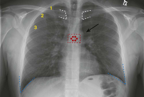
Figure 18-1 Normal chest radiograph (aka plain chest radiograph).
As with all films, one must first identify the type of film and the quality of the study; if these are appropriate, then one must systematically review the visible anatomic structures. For a chest radiograph, this includes the lung fields, the mediastinum, surrounding soft tissues, and the bony structures. There are also nonanatomic structures such as lines and implanted devices that should be reviewed. Keep in mind that the radiograph compresses three dimensions down to two, so there is loss of detail for which you need to account. Also, remember that the radiodensities of different structures in the chest may be the same, so the viewer often cannot differentiate between soft tissues. In fact, it is best to think of structures in terms of three densities: (1) air, (2) soft tissue and fluid, and (3) bone.
When interpreting the film, note the positioning of the patient and consider the direction of the radiation beam. Typically, radiographs are taken in one of three directions: AP, PA, and lateral.
 AP: the x-ray beam enters the front of the chest and hits the film, which is posterior to the patient (the portable chest radiograph is an AP study).
 PA: the x-ray beam enters the patient’s back and penetrates the chest before the film, which is placed along the patient’s anterior chest wall. The PA film is the preferred method of obtaining a chest radiograph, as it more accurately reflects the size of the cardiac and mediastinal silhouettes.
 Lateral view (often combined with the PA view): the radiation beam usually enters the right side of the patient, with the patient’s left side against the film.
 Additional views (or variations in above styles) are also possible if you need to evaluate particular findings. An example is a decubitus view, which might be obtained so as to differentiate a pleural effusion from consolidation.
Regarding the quality of the film, it is important to consider penetration, rotation, and inspiration. Penetration refers to the adequacy of the radiation dose given to expose the film. This dose is variable, since patients’ body sizes (i.e., amounts of subcutaneous soft tissue) are variable. An inadequate radiation dose will make it difficult to evaluate denser tissues such as bone and soft tissue. A high dose may overexpose the less-dense lung tissue, making it difficult to differentiate subtle patterns. An easy way to determine if a film is properly penetrated is by looking at the mediastinum; the vertebrae and the spinous processes should be easily visible (note the red dots on Figure 18-1). Rotation of the film can be determined by looking at the distance of the medial head of the clavicles from the spinous processes; they should be equidistant if there is no rotation (note the white dashes on Figure 18-1). Examining adequacy of inspiration is a fundamental part of deciding if a chest radiograph is adequate. A good inspiration will allow you to see 6 or more anterior ribs, or 10 or more posterior ribs, above the right hemidiaphragm (note the yellow numbers on the right anterior ribs on Figure 18-1). We have started the count for you. How many anterior ribs do you count above the right hemidiaphragm?
When evaluating the lung fields, there are numerous pathologic abnormalities that may be present; however, many of these abnormalities might appear the same on a chest radiograph. For this reason it’s best to think of the findings in terms of their radiographic appearance, which may help the reader arrive at a proper differential diagnosis. Things to note are the location of a finding, symmetry (i.e., does it appear on the contralateral side?), and whether a finding is associated with a previously known diagnosis.
For example, the appearance of a nodule (or small opacity) on a radiograph within the lung parenchyma (Fig. 18-2) can be caused by a number of entities such as neoplasm, granuloma, focal pneumonia, vascular phenomena (such as vessels on end), or an infarct. Knowing if the opacity was present previously can help you assess it for growth; increased growth over time often suggests malignancy. There are also particular properties that can help differentiate a benign from a malignant lesion, but they are not completely reliable; these are discussed in Chapter 17, Pulmonary Nodule.
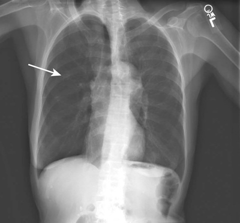
Figure 18-2 A solitary pulmonary nodule in the right chest (arrow).
Another important lung finding is a cavity (Fig. 18-3A and B). A cavity is an opacity that may appear to have a different density within it (i.e., the center may be more radiolucent). The interior of the cavity may contain fluid (see Fig. 18-3B) or other radio-opaque substance. Cavities may be malignant, may be caused by an infectious agent, or may result from an infarct.
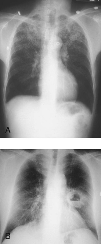
Figure 18-3 A, Radiolucent area in the left lung apex indicative of a lung cavity. B, A large, thick-walled cavitary lesion noted in the left chest with a horizontal opacity located within the cavity suggesting an air-fluid level.
More diffuse findings can be subtle and pose difficult diagnostic challenges. Generally, such diffuse findings should be described based on the pattern noted. Common patterns are consolidation, reticular, nodular, and cystic.
 A consolidation is generally a large single opacity in which the bronchial tree is visualized within the consolidation, so-called air bronchograms. The position of the opacity may give a hint as to its location. For example, if the right- or left-side heart borders are not preserved, the blurred border may indicate that there is a (contiguous) pneumonia affecting the right middle lobe (Fig. 18-4) or lingula, respectively. Consolidation patterns are typical of pneumonia.
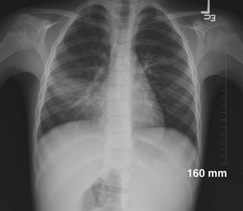
Figure 18-4 Consolidation of the right middle lobe. (Courtesy of Richard Ruchman, MD)
 A reticular pattern is one in which the opacity consists of multiple lines that often appear to be crisscrossing. Reticular patterns are often seen in connective tissue and fibrosing (interstitial scarring) diseases such as systemic lupus erythematosus and idiopathic pulmonary fibrosis. A reticular pattern may also be seen in specific types of pneumonia, such as pneumonia caused by Pneumocystis jirovecii.
 A nodular pattern is one in which the opacity consists of many distinct, small opacities as may be seen in patients with metastatic disease, sarcoidosis, miliary tuberculosis, or Langerhans cell histiocytosis (Fig. 18-5).
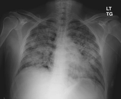
Figure 18-5 Diffuse nodular opacities affecting the lung bilaterally with relative sparing of the lung periphery.
 A cystic pattern is one in which numerous ring shapes are identified as may be seen in patients with bronchogenic cysts and pulmonary sequestrations.
The radiograph should be evaluated for effusion and proper diaphragmatic function. The costophrenic angles (note blue dashes on Fig. 18-1) are usually sharp, acute angles. Blunting of this angle is a sign of probable pleural effusion (Fig. 18-6).
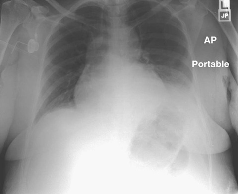
Figure 18-6 Dense opacification affecting the left hemithorax and obscuring the costophrenic angle suggestive of left pleural effusion.
The right and left hemidiaphragms should be visualized domes with the liver under the right hemidiaphragm and usually a gastric air bubble below the left side. Air immediately under the right hemidiaphragm implies free air in the abdomen, which may be seen with rupture of an intra-abdominal viscus or (normally) after laparotomy.
The heart silhouette is a two-dimensional representation of a three-dimensional organ. As the chest radiograph does not differentiate ventricular content from ventricular muscle, it is not a good measure of cardiac function; nonetheless, a heart that is more than 50% the width of the intrathoracic cavity on a PA film is highly suggestive of cardiomegaly (Fig. 18-7).
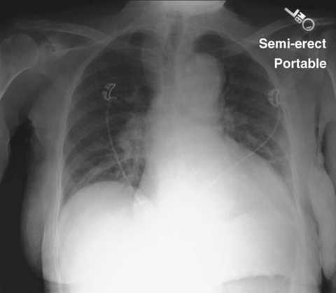
Figure 18-7 Cardiac silouhette encompassing more than 50% of the width of the intrathoracic cavity on a PA film.
A symmetrically enlarged heart (often termed the “water bottle” appearance) may be indicative of a pericardial effusion. Widening of the superior portion of the heart on the left may be evidence of left atrial enlargement.
Superior to the heart is the aorta. Usually the ascending and descending portions can be identified as well as the aortic notch (see arrow in Fig. 18-1). Widening of the mediastinum may be seen in patients with ascending aortic dissection, although it is not a specific phenomenon; for example, although an uncommon disease, inhalational anthrax can result in a widened mediastinum. On a nonrotated film, widening of the mediastinum often implies mediastinal pathology, so further investigation is warranted even if aortic dissection is not high on the pretest differential diagnosis.
Soft tissue is often overlooked by inexperienced readers of chest films, since examination of the soft tissues is generally not the reason for which the study was ordered. However, the soft tissues should always be carefully examined and incidental findings should be noted and appropriately addressed. When something visualized on the chest film appears abnormal, always check for symmetry. Generally, if a similar structure in the soft tissues cannot be identified on the contralateral side, it is more likely to be an abnormal finding. Soft-tissue edema or masses may often appear as simple areas of asymmetry.
Bones that appear on a chest radiograph include cervical through upper lumbar vertebrae, the ribs, the scapulae, and the right humerus and left humerus. Search for periosteal elevation and thickening along the edge of these bones, and look for fracture lines within the bones. Such bony findings are often subtle and easy to miss. Cystic structures within the bones may also be visible. Although these are rare findings, it is important to review these structures for completeness.
One additional issue to consider when looking at a chest radiograph is the multitude of radio-opaque foreign bodies that may be visible. Such radio-opaque bodies commonly include catheters, pacemakers, and defibrillators, as well as endotracheal and nasogastric tubes. It is important to note the position of these objects and to ensure that they terminate at anatomically appropriate positions. For example, typically the tip of an endotracheal tube should be 3 to 5 cm from the carina; the tip of a central line catheter should be in the superior vena cava just above the right atrium.
By using a systematic approach to interpreting the chest radiograph, even the novice reader may gain important information about the patient.
Consider the resources listed below for further learning regarding chest radiograph interpretation.
Suggested Readings
http://www.learningradiology.com
A detailed slide-based overview of basic chest radiograph interpretation (click on “Chest” from home page).
