[level-membership-for-neurosurgery-category]
Chapter 137 Spinal Implant Attributes
Distraction, Compression, and Three-Point Bending
Instrumentation techniques exert forces to the spine through six basic mechanisms: distraction, three-point bending, tension band fixation, fixed moment arm cantilever beam fixation, non–fixed moment arm cantilever beam fixation, and applied moment arm cantilever beam fixation.1,2 All of these mechanisms can be used individually or in combination. This chapter discusses in detail how various types of distraction, compression, and three-point bending implants carry these forces and redistribute them to the remainder of the spine and related tissues. Strategies are presented that can help prevent overloading any portion of the spine-implant combination (construct) and subsequent failure. The information presented in this chapter is an overview; more in-depth information may be gleaned from numerous sources.3–10 Implant-specific information is also available.11–14
Distraction Fixation
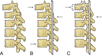
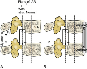
The use of distraction can be very effective in reestablishing spinal height. It can be applied from either a ventral interbody or a dorsal approach. However, it is uncommon to use distraction alone because it is difficult to apply forces directly in line of the instantaneous axis of rotation (IAR) or symmetrically around it. When distraction is applied away from the IAR, the resultant force develops a bending moment, as shown in Figure 137-1.
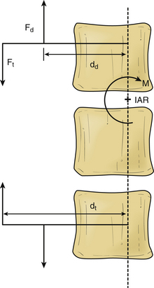
If we know the magnitude, the point and line of application of the distraction force, and the location of the IAR, we may predict the response of the spine segment.15 In these cases, the bending moment results in compression of the spine on the opposite side of the IAR from the site of distraction force application (Fig. 137-2).
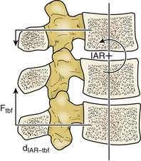
The ability to resist bending (originated by the distraction) is called moment of inertia15; this is usually derived from intrinsic spinal elements (e.g., ligaments). The moment of inertia can be increased by tensile structures (ligamentous or implant) that are farther from the IAR than the distraction forces. The bending moment can be eliminated by balancing the distraction and tensile forces as shown in the following equation:

where Fd and dd are the distraction force and lever arm length, and Ft and dt are the tensile force and moment arm length (see Fig. 137-1).
The development of bending moments is particularly problematic when the isolated distraction forces are applied dorsal to the IAR. This difficulty is due to the propensity to exaggerate pathologically or cause a kyphotic deformity. Simple dorsal distraction is uncommonly applied, although it can be combined with three-point bending fixation to impart desirable results.
Three-Point Bending Fixation
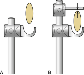
A pencil can be placed in three-point bending by placing the thumbs together in the center and the fingers at the ends and pushing on the center of the pencil with the thumbs. The resulting fulcrum directs a force vector opposite the direction of the terminal force vectors.1 The central force vector has twice the magnitude of the sum of the terminal force vectors and the opposite sign (Fig. 137-3).16 Three-point bending spinal instrumentation applies similar force vectors. They are usually, but not always, applied with an accompanying distraction force by using instrumentation such as Harrington distraction rods or universal spinal instrumentation.
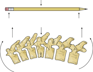
The bending moment generated by a three-point bending fixation construct is proportional to the length of the construct.17 Three-point bending implants usually involve application of dorsal instrumentation over multiple spinal segments (five or more spinal segments). The forces at the rostral and caudal implant-bone interfaces are usually dorsally directed. The central force is usually in the ventral direction. This central force is equal to the sum of the two dorsally directed forces and is normally located over the dorsal surface of the vertebra that requires decompression (see Fig. 137-3). If the dorsal surface of this central vertebra is damaged so that it would not resist the application of the force, the location of ventral force application can be moved to the vertebrae above and below the damaged vertebra. The result is four-point bending fixation. The effects are very similar to three-point bending fixation, but larger forces or longer moment arms (more spinal segments) are required to obtain the same bending moment and decompression. Using the previous example with a pencil, this concept can be visualized by moving the thumbs apart while keeping the fingers in the same location when bending the pencil.

The forces and lengths are as defined in Figure 137-4A, and the system is assumed to be at rest. The requirement that the sum of the three forces be zero can be used to derive the moment in terms of the central force,11 as follows:
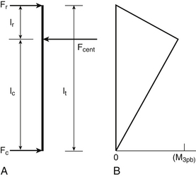


Figure 137-4B shows that the moment decreases linearly from the central loading point until it reaches a value of zero at the terminal loading points.
As discussed earlier, it is rare to apply isolated dorsal distraction forces; this is because dorsal distraction also results in flexion of the spine, as the IAR is ventral to the force application points. Because three-point bending fixation opposes this flexion, it is common to combine the two modes of force application. The application of sufficient dorsal distraction is needed so that the implant makes contact with the spine at the intermediate point along the construct (fulcrum), which is usually at the level of the pathology site; this can be accomplished by bending the rod so that it makes contact with the spine at the location at which the ventral force application is desired or by using a sleeve to increase the diameter of the rod at this location.14 Nevertheless, this technique has major disadvantages: (1) Achieving proper rod modeling is highly difficult; (2) multiple bends fatigue the rod and may result in failure; and (3) round rods can rotate at the hook interface so that the bend is no longer in the sagittal plane.
Terminal Three-Point Bending Fixation
The term terminal three-point bending fixation is used to define a three-point bending construct that corrects sagittal deformation situated at the rostral end of an implant. In this case, the fulcrum is situated near one end of the construct.1 The moment arm attained by a terminal construct is less than the moment arm attained for a similar three-point bending construct where the fulcrum is in the midportion.
This type of construct may be useful in the clinical scenario of a sagittal deformation where the rostral segment is translated in a ventral direction with respect to the more caudal segment.1,17 In this case, the use of a terminal three-point bending fixation construct results in reduction of translational deformation. It eliminates the pressure on the spinal cord by the dorsal surface of the spinal canal. Application of the ventral force by using the rostral terminus is much easier because the vertebra to be moved can be affixed to the rod, while the remainder of the rod is used as a lever (Fig. 137-5). In this application, the length of the rostral portion (lr) is normally quite short (one segment), and the length of the caudal portion (lc) is longer (two to four segments), which allows a large rostral force with application of a small caudal force.
Combined Distraction and Three-Point Bending Fixation
Combined distraction and three-point bending fixation creates a more complex loading state; this is particularly evident at the terminal rod hook, as shown in Figure 137-6 for the rostral terminus. The resultant force at the hook is the vector sum of all of the distraction and dorsal bending forces and is described by the following equation:
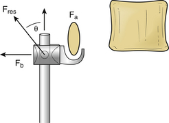

where Fa and Fb are the distraction and three-point bending forces, and Fres is the resultant force. The magnitude and direction of this force are shown by the following equation:
where θ is the angle between the resultant and axial forces.
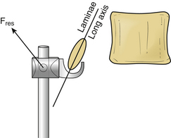
Combined distraction and three-point bending constructs result in the terminal force vectors being oriented at an angle with respect to the spinal axis. This may be a suboptimal orientation of the force vector for two reasons. First, the inclined force vector can result in loading of the lamina in a weak direction; this is particularly dramatic if the long axis of the lamina cross section is perpendicular to the loading direction, as shown in Figure 137-7. The lamina carries pure distraction or pure bending loads better than the combined load because its moment of inertia is higher in these directions. Second, when the rod terminus is being used to correct a kyphotic deformation, the inclined force vector distracts the rostral vertebra and rotates it dorsally. Both problems can be mitigated by clamping the rod to laminae between the center and the terminus, which divides the load between two or more laminae. Careful positioning of the clamps allows the forces on the terminal vertebra to be almost entirely distraction forces or entirely bending forces.
Tension Band (Compression) Fixation
Tension band fixation develops bending moments in the compressed segments that can cause flexion or extension according to its location. The magnitude of the bending moment for the tension band fixation construct (Mtbf) is the result of the compression force applied by the tension band (Ftbf) by the perpendicular distance from the IAR to the applied force (dIARtbf), as shown in Figure 137-8 and the following equation:


Where Si is the stiffness of the implant, and li is the length of the implant. For rigid constructs and wires, the force reaches zero with very little decrease in the interanchor distance because the stiffness of the implant is so high, as in the following equation:

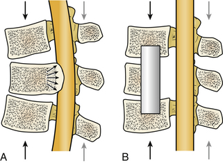
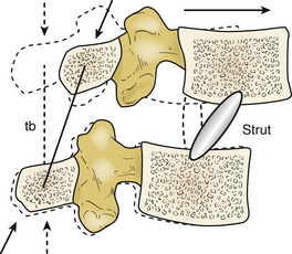
One problem with tension band fixation is that extradural masses (bone or disc fragments) can be thrust into the spinal canal during application of instrumentation. Decompression procedures may be appropriate before the application of the implant. Another disadvantage for this type of construct is the inability to bear axial loads by themselves; if axial load bearing is inadequate, it must be restored (Fig. 137-9). Another drawback is the inability to control translational movements well, as shown in Figure 137-10. This motion may be accentuated if the distance between the insertion points of the tension band is decreased. Significant spinal integrity must be present when tension band fixation is used.
Loading of Rigid or Semirigid Distraction and Compression Constructs
When the patient assumes an upright posture, the implant must bear a load approximately equal to the weight of the torso above it.17 The nature of the forces that the implant has to bear depends on the mode of insertion (compression, neutral, or distraction) and on the location of the implant.
The center of gravity line of the body generally falls ahead of the lumbar spine, which creates a net forward bending moment.18 Spinal structures ventral to the normal IAR (IARn) become compressed, and structures that are dorsal are tensioned during the assumption of the upright posture. For this reason, the physiologic loads on the implant depend on the location of the implant. The fact that any modification of the spinal structure during surgery changes the flexural rigidity of the functional spinal unit and the location of the IAR should also be considered.
In the case of disc or vertebral body replacement with a bone graft (strut), the IAR changes its location toward the position of the implant because the axial rigidity of the implant acts as a pivot point for intervertebral motion. It generates a bending moment, which causes extension in the spine. Forces that resist forward bending moment (moment of inertia) at the dorsal spine structures and implants located in this area are much lower than the forces applied to normal anatomy. This is because the moment arm available to resist the bending moment is longer (Fig. 137-11).
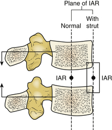
FIGURE 137-11 Effect of ventral strut on instantaneous axis of rotation (IAR) and forces resulting from physiologic loading.
When the strut is located dorsally to the normal IAR, dorsal structures and any dorsal tension band construct are subjected to much larger forces that resist forward bending. This situation is the result of a longer moment arm for forward bending and shorter moment arm for the dorsal structures (Fig. 137-12A). To compensate this construct, a compressive implant can be installed on the ventral side of the normal IAR. It supports part of the compressive load and moves the IAR ventrally to alleviate these large loads as shown in Figure 137-12B.
The net forces on an implant during use are found by a vector summation of the forces resulting from physiologic and surgical loading. In the case of upright posture, the addition of axial loading to the construct increases or decreases the net forces according to the location of the implant.
The forces borne by distractive implants located dorsal to the IAR and compressive implants located ventral to the IAR are reduced or change the sign on application of the physiologic loads. This activity is due to the ventral location of the center of gravity of the spine with respect to the IAR. The resulting bending moment applies a tensile force to dorsal spinal elements and a compressive force to ventral spinal elements. Reduction of the forces borne by the implant is a form of load sharing. It minimizes complications because the deformation caused by physiologic loading is in the same orientation as that from the surgical loading (dorsal distraction or ventral compression). However, reversal of the forces borne by the implant may cause problems if the implant is normally designed to bear only one type of load. An excellent example is the disengagement of hooks from the laminae in Harrington distraction rods. This disengagement occurs when the distance between the laminae increases in response to the physiologic loading, as shown in Figure 137-13A. This problem can be prevented by placing opposing hooks (claw) around the laminae so that the implant becomes a compressive implant on load reversal (Fig. 137-13B). Screw-based implants do not produce this problem, because they are rigidly attached to both the vertebra and the rod.
Comparison of Three-Point Bending and Tension Band Fixation
Both three-point bending and tension band fixation can be used to generate therapeutic bending moments in the spine. However, the methods by which they generate these moments are significantly different. The three-point bending fixation technique generates bending moments that are proportional to the length of the construct. This technique usually requires a long construct to optimize its efficacy.17 The moment arm applied by the three-point bending construct is parallel to the long axis of the spine (Fig. 137-14).
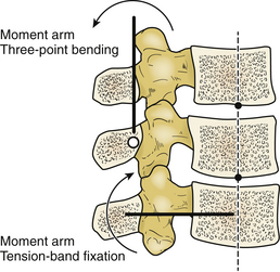
Tension band fixation techniques are independent of implant length. They may be used with only two segments. The moment arm applied by a tension band implant is perpendicular to the long axis of the spine (see Fig. 137-14).17
If the equations for three-point bending and tension band fixation are solved simultaneously, it can be proved mathematically that in achieving equal bending moments, the moment arm for three-point bending should be four times longer.1,17 Three-point bending implants are usually employed over more spinal segments, typically five or more, compared with tension band fixation implants, which typically employ two or three segments.
A ventrally directed force is often desirable at the point of spine fracture to reduce the fractured vertebra ventrally. Tension band fixation constructs may be undesirable because the effective ventrally directed force applied at the fulcrum (fracture) decreases with increasing distance between the attachment points. This decrease is a result of either a progressive increase of the lever arm (dIAR-ibf) as the spine extends or the spine buckling as the fracture site returns to a kyphotic orientation as shown in Figure 137-15. In addition, long constructs may cause hyperextension of the spine by creating terminal bending moments.1
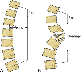
The spine is a very inhomogeneous structure composed of stiff, rigid vertebrae connected through much more flexible discs. In addition, a damaged spine often contains regions with almost no stiffness and rigidity, where portions of one or more vertebrae have been removed. The ventral forces and resulting displacements for tension band constructs vary greatly along the construct and from installation to installation. If a ventral force is required in a specific location, it is better to use a three-point bending fixture to place this force precisely.
Three-point bending fixation techniques often incorporate distraction forces applied at the terminal (and intermediate) implant-bone interfaces. These distraction forces increase the stresses applied to the bone as discussed earlier. However, the bending moment is not changed if the central ventral force and the terminal dorsal forces are not changed. Some authors have advocated using exaggerated distraction forces in conjunction with three-point bending to accomplish spinal column reduction and spinal canal decompression.4 However, this approach has not always met with success, because of the “sagittal bowstring” effect11 and fracture of the dorsal fixation site.
Benzel E.C. Biomechanics of spine stabilization: principles and practice. Rolling Meadows, IL: American Association of Neurological Surgeons; 2001.
Benzel E.C., Kayanja M., Fleischman A., et al. Spine biomechanics: fundamentals and future. Clin Neurosurg. 2006;53:98-105.
Boos N., Aebi M. Spinal disorders: fundamentals of diagnosis and treatment. Berlin: Springer-Verlag; 2008.
Dickman C.A., Fehlings M.G., Gokaslan Z.L. Spinal cord and spinal column tumors: principles and practice. New York: Thieme Medical; 2006.
Schlenk R.P., Kowalski R.J., Benzel E.C. Biomechanics of spinal deformity. Neurosurg Focus. 2003;14:e2.
White A.A., Panjabi M.M. Clinical biomechanics of the spine, ed 2. Philadelphia: Lippincott-Raven; 1990.
1. Benzel E.C. Biomechanics of spine stabilization: principles and practice. Rolling Meadows, IL: American Association of Neurological Surgeons; 2001.
2. Benzel E.C., Kayanja M., Fleischman A., Roy S. Spine biomechanics: fundamentals and future. Clin Neurosurg. 2006;53:98-105.
3. Benzel E.C. Biomechanics of lumbar and lumbosacral spine fractures. In: Rea G.L., editor. Spinal trauma: current evaluation and management. Rolling Meadows, IL: American Association of Neurological Surgeons, 1993.
4. Breig A. Adverse mechanical tension in the central nervous system: an analysis of cause and effect: relief by functional neurosurgery. New York: Almqvist & Wiskell; 1978.
5. Carson W.L., Duffield R.C., Arendt M., et al. Internal forces and moments in transpedicular spine instrumentation. Spine. 1990;15:893-901.
6. Goel V.K., Weinsein J.N. Biomechanics of the spine: clinical and surgical perspective. Boca Raton, FL: CRC Press; 1989.
7. Goel V.K., Lim T.-H., Gwon J., et al. Effects of rigidity on an internal fixation device, a comprehensive biomedical investigation. Spine (Phila Pa 1976). 1991;16:S155-S161.
8. Lindahl O. Mechanical properties of dried defatted spongy bone. Acta Orthop Scand. 1976;47:11.
9. White A.A., Panjabi M.M. Clinical biomechanics of the spine, ed 2. Philadelphia: Lippincott-Raven; 1990.
10. Yoganandan N., Larson S.J., Pintar F., et al. Biomechanics of lumbar pedicle screw/plate fixation in trauma. Neurosurgery. 1990;27:873-881.
11. Benzel E.C. Biomechanics of spine stabilization: principles and practice. New York: McGraw-Hill; 1995.
12. Benzel E.C., Larson S.J. Operative stabilization of the posttraumatic thoracic and lumbar spine: a comparative analysis of the Harrington distraction rod and the modified Weiss spring. Neurosurgery. 1986;19:378-385.
13. Benzel E.C., Kesterson L., Marchand E.P. Texas Scottish Rite Hospital rod instrumentation for thoracic and lumbar spine trauma. J Neurosurg. 1991;75:382-387.
14. Edwards C.C., Levine A.M. Early rod-sleeve stabilization of the injured thoracic and lumbar spine. Orthop Clin North Am. 1986;17:121-145.
15. DeWald R. Spinal deformities: the comprehensive text. New York: Thieme Medical; 2003.
16. Schlenk R.P., Kowalski R.J., Benzel E.C. Biomechanics of spinal deformity. Neurosurg Focus. 2003;14:e2.
17. Dickman C.A., Fehlings M.G., Gokaslan Z.L. Spinal cord and spinal column tumors: principles and practice. New York: Thieme Medical; 2006.
18. Boos N., Aebi M. Spinal disorders: fundamentals of diagnosis and treatment. Berlin: Springer-Verlag; 2008.
[/level-membership-for-neurosurgery-category][not-level-membership-for-neurosurgery-category]
Chapter 137 Spinal Implant Attributes
Distraction, Compression, and Three-Point Bending
Instrumentation techniques exert forces to the spine through six basic mechanisms: distraction, three-point bending, tension band fixation, fixed moment arm cantilever beam fixation, non–fixed moment arm cantilever beam fixation, and applied moment arm cantilever beam fixation.1,2 All of these mechanisms can be used individually or in combination. This chapter discusses in detail how various types of distraction, compression, and three-point bending implants carry these forces and redistribute them to the remainder of the spine and related tissues. Strategies are presented that can help prevent overloading any portion of the spine-implant combination (construct) and subsequent failure. The information presented in this chapter is an overview; more in-depth information may be gleaned from numerous sources.3–10 Implant-specific information is also available.11–14
Distraction Fixation
The use of distraction can be very effective in reestablishing spinal height. It can be applied from either a ventral interbody or a dorsal approach. However, it is uncommon to use distraction alone because it is difficult to apply forces directly in line of the instantaneous axis of rotation (IAR) or symmetrically around it. When distraction is applied away from the IAR, the resultant force develops a bending moment, as shown in Figure 137-1.
If we know the magnitude, the point and line of application of the distraction force, and the location of the IAR, we may predict the response of the spine segment.15 In these cases, the bending moment results in compression of the spine on the opposite side of the IAR from the site of distraction force application (Fig. 137-2).
The ability to resist bending (originated by the distraction) is called moment of inertia15; this is usually derived from intrinsic spinal elements (e.g., ligaments). The moment of inertia can be increased by tensile structures (ligamentous or implant) that are farther from the IAR than the distraction forces. The bending moment can be eliminated by balancing the distraction and tensile forces as shown in the following equation:
where Fd and dd are the distraction force and lever arm length, and Ft and dt are the tensile force and moment arm length (see Fig. 137-1).
The development of bending moments is particularly problematic when the isolated distraction forces are applied dorsal to the IAR. This difficulty is due to the propensity to exaggerate pathologically or cause a kyphotic deformity. Simple dorsal distraction is uncommonly applied, although it can be combined with three-point bending fixation to impart desirable results.
Three-Point Bending Fixation
A pencil can be placed in three-point bending by placing the thumbs together in the center and the fingers at the ends and pushing on the center of the pencil with the thumbs. The resulting fulcrum directs a force vector opposite the direction of the terminal force vectors.1 The central force vector has twice the magnitude of the sum of the terminal force vectors and the opposite sign (Fig. 137-3).16 Three-point bending spinal instrumentation applies similar force vectors. They are usually, but not always, applied with an accompanying distraction force by using instrumentation such as Harrington distraction rods or universal spinal instrumentation.
The bending moment generated by a three-point bending fixation construct is proportional to the length of the construct.17 Three-point bending implants usually involve application of dorsal instrumentation over multiple spinal segments (five or more spinal segments). The forces at the rostral and caudal implant-bone interfaces are usually dorsally directed. The central force is usually in the ventral direction. This central force is equal to the sum of the two dorsally directed forces and is normally located over the dorsal surface of the vertebra that requires decompression (see Fig. 137-3). If the dorsal surface of this central vertebra is damaged so that it would not resist the application of the force, the location of ventral force application can be moved to the vertebrae above and below the damaged vertebra. The result is four-point bending fixation. The effects are very similar to three-point bending fixation, but larger forces or longer moment arms (more spinal segments) are required to obtain the same bending moment and decompression. Using the previous example with a pencil, this concept can be visualized by moving the thumbs apart while keeping the fingers in the same location when bending the pencil.
The forces and lengths are as defined in Figure 137-4A, and the system is assumed to be at rest. The requirement that the sum of the three forces be zero can be used to derive the moment in terms of the central force,11 as follows:
Figure 137-4B shows that the moment decreases linearly from the central loading point until it reaches a value of zero at the terminal loading points.
As discussed earlier, it is rare to apply isolated dorsal distraction forces; this is because dorsal distraction also results in flexion of the spine, as the IAR is ventral to the force application points. Because three-point bending fixation opposes this flexion, it is common to combine the two modes of force application. The application of sufficient dorsal distraction is needed so that the implant makes contact with the spine at the intermediate point along the construct (fulcrum), which is usually at the level of the pathology site; this can be accomplished by bending the rod so that it makes contact with the spine at the location at which the ventral force application is desired or by using a sleeve to increase the diameter of the rod at this location.14 Nevertheless, this technique has major disadvantages: (1) Achieving proper rod modeling is highly difficult; (2) multiple bends fatigue the rod and may result in failure; and (3) round rods can rotate at the hook interface so that the bend is no longer in the sagittal plane.
Terminal Three-Point Bending Fixation
The term terminal three-point bending fixation is used to define a three-point bending construct that corrects sagittal deformation situated at the rostral end of an implant. In this case, the fulcrum is situated near one end of the construct.1 The moment arm attained by a terminal construct is less than the moment arm attained for a similar three-point bending construct where the fulcrum is in the midportion.
This type of construct may be useful in the clinical scenario of a sagittal deformation where the rostral segment is translated in a ventral direction with respect to the more caudal segment.1,17 In this case, the use of a terminal three-point bending fixation construct results in reduction of translational deformation. It eliminates the pressure on the spinal cord by the dorsal surface of the spinal canal. Application of the ventral force by using the rostral terminus is much easier because the vertebra to be moved can be affixed to the rod, while the remainder of the rod is used as a lever (Fig. 137-5). In this application, the length of the rostral portion (lr) is normally quite short (one segment), and the length of the caudal portion (lc) is longer (two to four segments), which allows a large rostral force with application of a small caudal force.
[/not-level-membership-for-neurosurgery-category]
