[level-membership-for-neurosurgery-category]
Chapter 138 Spinal Implant Attributes
Cantilever Beam Fixation
Cantilever
A cantilever beam is simply defined as a beam that is rigidly supported only at one end and carries a load. Examples of this commonly used engineering construct are numerous (Fig. 138-1). Spinal instrumentation constructs using cantilever beams are also common.1,2 It is important to recognize, however, that spinal instrumentation constructs are rarely composed of pure cantilever beams and may function otherwise in different clinical scenarios and when challenged with other stresses or moments.

FIGURE 138-1 Cantilever street signs on the grounds of the Wood National Cemetery, Milwaukee, Wisconsin.
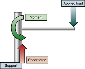
An idealized cantilever beam is shown in Figure 138-2. A load applied to the beam is resisted by shear stress and a moment at the point of attachment to the support. In this idealized situation, with axial loading, the beam experiences a shear stress parallel to the z-axis (vertical) and a moment. This moment consists of a force and an instantaneous axis of rotation about which the force is applied.3
Cantilevers in Spinal Instrumentation
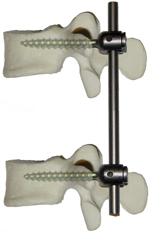
Cantilevers are frequently used in modern constrained spinal instrumentation. Figure 138-3 depicts a simple idealized short-segment nonsegmental spinal instrumentation construct. Such a construct has been termed cantilever beam fixation1,2 Brief analysis reveals the presence of four potential cantilevers. Each screw is a cantilever beam supported by the vertebral body support. Each rod is a cantilever beam supported by a screw support. Analysis of such a complex system requires either significant simplification or separate analysis of each component before considering the properties of the entire system.
Bone-Screw Cantilever
Resistance to Shear Stress
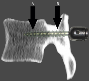
The shear stress resistance of a typical screw is typically much greater than the resistance of the bone in which is embedded. Resistance to shear stress at the bone-screw interface is primarily determined by the mechanical properties of the bone composing the vertebra. An idealized diagram of a vertebral body is shown in Figure 138-4. The screw traverses a finite thickness of cortical bone, entering the cancellous bone of the central vertebral body. Shear stress resistance is a function of the relative contributions of the bone-screw interfaces in these locations. This contribution is related to the yield strength of the material, the stress at which a material begins to deform plastically, and the area of contact. Although the cancellous bone has significantly lower yield strength, this property is mitigated by the larger area of the bone-screw interface. The total shear stress resistance is the sum of the values for the engaged areas of cortical and cancellous bone.
Resistance to Bending Moment
Resistance to y-plane bending moment is more complex. An idealized diagram of a screw and vertebral body is depicted in Figure 138-5. The effect of differing material properties between the screw, cortical bone, and cancellous bone produces a complex interaction.
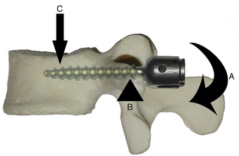
A refined definition of a cantilever is a load-bearing member, such as a beam, that projects beyond a fulcrum and is supported by a balancing member or a downward force behind the fulcrum. This definition applies more accurately to resistance to bending moment at the bone-screw interface below the threshold for cortical bone failure—its yield strength. Because of the difference in yield strength of the two types of bone, the cortical bone at the entrance to the vertebral body, particularly in the region of the pedicle, can be regarded as a fulcrum. The screw functions as the load-bearing beam. A load is applied to the head of the screw across the instantaneous axis of rotation at the cortical fulcrum, creating a moment. The magnitude of this moment varies in accordance with the formula: moment = force × distance (from the fulcrum). The resisting moment is generated by downward stress applied by the body of the screw behind the fulcrum. With only the short screw head protruding beyond the cortex, the applied moment may be quite low because the length of the level arm is minimal unless extended by connection to other implants.
Failure at the bone-screw interface occurs in response to a bending moment if the yield strength of either the fulcrum (cortical bone) or the downward force (cancellous bone) behind the fulcrum is exceeded.4 The yield strength for both regions is increased with increased contact area. This is a function of both screw diameter (cortical and cancellous) and screw length (relevant only for the cancellous portion). An increase in screw length increases contact area only in the cancellous region, whereas contact area is fixed for a given screw diameter and a given thickness of cortical bone at the entrance. In addition, longer screws increase resistance to a bending moment by increasing the distance between the cortical fulcrum and the distal tip of the screw, increasing the moment of the resistive force in the cancellous region.
In response to a bending moment, the mechanical properties of the screw shaft may also be relevant. The bending resistance of the screw is related to the area moment of inertia, determined primarily by the minor diameter of the screw. For a screw of circular cross section, elastic resistance to a bending moment is proportional to the fourth power of the minor diameter.5 The bending moment is least at the proximal and distal end of the screw and is inversely proportional to the distance from the fulcrum. The bending moment reaches its maximum at the point of the cortical fulcrum. The advantage of a larger-diameter screw lies not only in the increased contact area between the screw and the bone behind the fulcrum but also in the larger area moment of inertia. The use of a longer screw increases both the area of bone-screw contact and the length of the lever arm in cancellous bone behind the fulcrum, although this effect occurs at the expense of increasing bending moment at the screw entry point.
Screw-Rod Interface
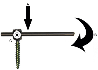
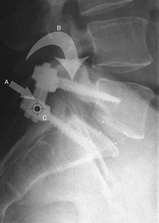
Under certain circumstances, the screw-rod interface may also function as a cantilever. In this case, the screw functions as the support and the rod as the beam. A simplified diagram is shown in Figure 138-6. When functioning as a cantilever, a shear stress is applied parallel to the long axis of the screw (the support), and a coplanar moment is applied to the rod (the beam) with an instantaneous axis of rotation near the screw-rod junction. Certain clinical applications place significant cantilever stress on the screw-rod junction, most commonly reduction and internal fixation of a mobile spondylolisthesis (Fig. 138-7).
In the example of a construct such as depicted in Figure 138-3, this loading mode is unlikely to be encountered, and the screw-rod interface rarely functions as a cantilever. In most instances, including that depicted in Figure 138-3, the screw and rod frequently function as a single unit, with the rod acting as an extension of the beam (the screw) of the bone-screw cantilever. Lengthening of the rod significantly increases the moment applied across the cortical fulcrum at the entrance of the screw into the vertebral body. All elements of the beam experience a bending moment, although stress within the rod and screw increases toward the fulcrum. The maximum bending resistance of the unit is determined by the material properties of the components and the balance between the area moment of inertia and forces applied to each. Generally, however, thin components placed closest to the fulcrum are most subject to failure.
Clinical Modes of Failure and Strategies to Reduce Their Incidence
Bone-Screw Interface
Strategies to Increase the Resistive Moment
• The use of larger-diameter screws provides several advantages. First, larger-diameter screws increase the contact area between the screw and both the cortical and the cancellous bone. Increased contact area increases the yield strength in both regions.6–8 Second, larger-diameter screws possess an increased area moment of inertia, also improving the bending resistance.9 Disadvantages of this strategy include frequent anatomic constraints, in particular, with midthoracic transpedicular screws, where pedicle diameter may substantially limit screw diameter.
• Longer shaft screws also provide several advantages. The use of longer screws also increases the contact area between the screw and bone, although only in the cancellous region. For a given screw diameter and a given thickness of cortical bone, contact area in the cortical region is fixed. This increased contact area increases the yield strength of the cancellous region. Longer screws likewise increase the length of the lever arm behind the fulcrum; this produces an increase in bending resistance proportional to the increase in screw length. Much has been written about the relative merits of increased screw length, usually noting an increase in pull-out strength.10 In the situation where screws are used as cantilevers, bending resistance is a more relevant consideration.
• The use of additional screws in a given vertebra has been shown to increase the bending resistance in certain instances. This strategy is primarily relevant for lateral vertebral body screws where the choice of one or two screws per vertebra is accompanied by significant technical limitations. Doubling the number of screws per level theoretically doubles the bending resistance of the parallel cantilevers. In practice, however, the use of additional screws is associated with only a modest increase in bending resistance, which is level-dependent and introduces a new failure mode—failure by fracture of the cortical bone.11
• Augmentation of cancellous bone with various types of bone cement has also been used in an effort to increase the yield strength. The disadvantages of this strategy are primarily technical and include cement extravasation, emboli, potential difficulty with revision, and permanence. This strategy has been tested primarily with regard to pure pull-out.6,12–14
• Augmentation of cortical bone by the use of a staple at the entry point of a cantilevered anterior vertebral body screw may increase the effective yield strength of the cortical bone in that region.4,15 This technique may be particularly relevant at the rostral and caudal ends of the construct where deformational forces are predicted to be greatest.
Strategies to Decrease the Applied Moment
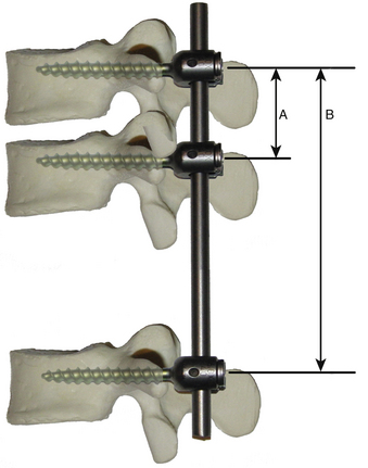
• The use of additional intervening screws (segmental fixation) has been examined in detail in the clinical and in the laboratory environment. For an otherwise mobile spine, the primary advantage of using intervening screws is related to the decrease in the length of the lever arm applied to the cantilever. Consider the diagram depicted in Figure 138-8. The rostral bone-screw interface experiences a moment proportional to the length of the lever arm, in this case determined primarily by the length of rod between fixation points. An intervening screw substantially decreases the length of this lever arm and proportionally decreases the magnitude of the applied moment. The addition of an intervening screw also changes the function of the other two screws, which function as a cantilever with the rod as the beam. The middle screw acts as a fulcrum, and the remote screw acts as an anchor. Also, these screws are subjected to a pure pull-out stress depending on the direction of the moment.
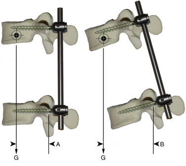
• Numerous strategies have been designed to modify the magnitude of the applied bending moment. Figure 138-9 is a simplified diagram of the forces acting on the beam of a bone-screw cantilever. At rest, the primary force acting on the lever arm is gravity. The length of the lever arm is the horizontal distance between the fulcrum and the distal end of the lever arm. When the distal end of the lever arm is in line vertically with the fulcrum, the bone-screw interface experiences primary shear force, which it is better equipped to neutralize. Proper posture during the healing process helps protect the bone-screw interface from potentially excessive moments. Attention to sagittal balance, in particular, excessively positive (kyphotic) balance, may produce the same effect. A large study of surgical outcomes after adult scoliosis surgery confirmed that nonunion, loss of correction, and instrumentation failure all are more common when acceptable sagittal balance is not achieved.16 Bracing, in addition to encouraging proper posture, decreases the magnitude of the moment by way of a buttressing effect.
• Many studies have confirmed the utility of anterior column reconstruction in cases where this is compromised.17 Ventral column support has at least two potential effects on a dorsal nonsegmental instrumentation construct. First, provision of anterior column support decreases shear stress at the bone-screw interface through load sharing. Second, rigid anterior support in some instances may modify the function of the instrumentation. If the anterior column is bearing most of the axial stress, the instantaneous axis of rotation at an individual vertebral body may be shifted forward such that the construct functions as a tension band and the bone-screw interface experiences primarily shear stress.
Screw-Rod Interface
In a typical clinical situation where contemporary instrumentation systems are used, the bending resistances of the screw head, screw-rod coupler, and rod are rarely exceeded. However, cyclic loading of the metallic components occurs with activity. Over time, this cyclic loading results in the development of progressive and localized damage within the metallic components, and the bending resistance is reduced. With continued cyclic loading, the bending resistance may become less than the applied moment, and failure may occur.1 There has been a trend in instrumentation design toward consideration of this degradation, which has seemingly decreased the incidence of failure in this region. Nevertheless, numerous strategies exist that are designed to reduce the incidence of failure at the screw-rod interface.
Strategies to Reduce the Incidence of Implant Failure at the Screw-Rod Interface
• Use of larger-diameter screws generally increases the bending resistance of the screw in response to an applied moment. This increased resistance is particularly important in the critical area adjacent the entry point of the screw into the bone where the bending moment is greatest.
• Formerly, many spinal instrumentation systems included components with particularly small diameter at the screw-rod interface. This deficiency has been largely corrected in modern implants.1
• Formerly, patients were subjected to long periods of bed rest to reduce the incidence of implant failure before the occurrence of fusion. It is now generally accepted that early mobilization decreases the incidence of complications and improves clinical outcomes. Bracing has been used to decrease the number and magnitude of load cycles applied to the instrumented spine. Although a detailed discussion of bracing techniques is beyond the scope of this chapter, it is important to consider that bracing primarily limits bending moments and must engage segments both above and below the instrumented segments to act as more than an “irritative reminder.” Bracing of the L5-S1 segment requires extension to the thigh for optimal effectiveness.
• Application of reduction forces is often an integral part of the surgical procedure. When these forces are applied in the axial plane, as in the reduction of a spondylolisthesis, the screw-rod junction experiences a cantilever force. However, when application of these forces is not an integral portion of the procedure, every effort should be made to avoid prestressing of the instrumentation during placement. This situation is facilitated by careful contouring of the rod, judicious adjustment of screw head height, and avoidance of unnecessary use of rod reduction instruments (“persuaders”).
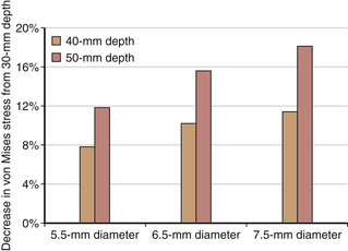
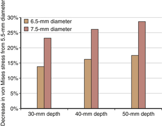
To illustrate the preceding concepts, a simple two-dimensional finite element model of vertebra-screw-rod was developed, and parametric studies were conducted using the following variables: diameter of screw 5.5 mm, 6.5 mm, and 7.5 mm and depth of screw insertion into the cortical shell–cancellous core of the vertebra 30 mm, 40 mm, and 50 mm. Assuming linear elastic analysis, a vertical load of 50 N was applied on the screw end. The maximum von Mises stress occurred at the contact of the screw with the cortical shell. Stresses decreased with increased insertion depth for the same screw diameter and decreased with increased screw diameter for the same insertion depth (Figs. 138-10 and 138-11). Although the analysis was limited to illustrate the load-sharing concept between the bone and the screw, local principal stress and strain responses may approach or exceed the yield strain of a human vertebra.
Costanzo F., Plesha M.E., Gray G.L. Engineering mechanics: statics and dynamics. Boston: McGraw-Hill; 2010.
Hollowell J.P., Yoganandan N., Benzel E.C. Spinal implant attributes: cantilever beam fixation. In: Benzel E.C., editor. Spine surgery. Techniques, complication avoidance, and management. ed 2. Philadelphia: Churchill Livingstone; 2005:1418-1429.
Kim Y.J., Bridwell K.H., Lenke L.G., et al. Pseudarthrosis in long adult spinal deformity instrumentation and fusion to the sacrum: prevalence and risk factor analysis of 144 cases. Spine (Phila Pa 1976). 2006;31:2329-2396.
Masaki T., Sasso Y., Miura T., et al. An experimental study on initial fixation strength in transpedicular screwing augmented with calcium phosphate cement. Spine (Phila Pa 1976). 2009;34:E724-E728.
Rajpal S., Resnick D.K. Rod cantilever techniques. Neurosurgery. 2008;63:A157-A162.
1. Hollowell J.P., Yoganandan N., Benzel E.C. Spinal implant attributes: cantilever beam fixation. In: Benzel E.C., editor. Spine surgery. Techniques, complication avoidance, and management. ed 2. Philadelphia: Churchill Livingstone; 2005:1418-1429.
2. Rajpal S., Resnick D.K. Rod cantilever techniques. Neurosurgery. 2008;63:A157-A162.
3. Costanzo F., Plesha M.E., Gray G.L. Engineering mechanics: statics and dynamics. Boston: McGraw-Hill; 2010.
4. Mahar A.T., Brown D.S., Oka R.S., et al. Biomechanics of cantilever “plow” during anterior thoracic scoliosis correction. Spine J. 2006;6:572-576.
5. Anderson P.A., Oza A.L., Puschak T.J., et al. Biomechanics of occipitocervical fixation. Spine (Phila Pa 1976). 2006;31:755-761.
6. Kliner D.W., Wybo C.D., Sterba W., et al. Biomechanical analysis of different techniques in revision spinal instrumentation: larger diameter screws versus cement augmentation. Spine (Phila Pa 1976). 2008;33:2618-2622.
7. Skinner S.R., Maybee J., Transfeldt E., et al. Experimental pullout testing and comparison of variables in transpedicular screw fixation: a biomechanical study. Spine (Phila Pa 1976). 1990;15:195-201.
8. Zhang Q.H., Tan S.H., Chou S.M. Investigation of fixation screw pull-out strength on human spine. J Biomech. 2004;37:479-485.
9. Wittenberg R.H., Lee K.S., Shea M., et al. Effect of screw diameter, insertion technique, and bone cement augmentation of pedicular screw fixation strength. Clin Orthop Relat Res. 1993;296:278-287.
10. Seller K., Wahl D., Krauspe R., et al. Pullout strength of anterior spinal instrumentation: a product comparison of seven screws in calf vertebral bodies. Eur Spine J. 2007;16:1047-1054.
11. Mohamad F., Oka R., Mahar A., et al. Biomechanical comparison of the screw-bone interface: optimization of 1 and 2 screw constructs by varying screw diameter. Spine (Phila Pa 1976). 2006;31:E535-E539.
12. Chen L.H., Tai C.L., Lai P.L., et al. Pullout strength for cannulated pedicle screws with bone cement augmentation in severely osteoporotic bone: influences of radial hole and pilot hole tapping. Clin Biomech (Bristol, Avon). 2009;24:613-618.
13. Frankel B.M., Jones T., Wang C. Segmental polymethylmethacrylate-augmented pedicle screw fixation in patients with bone softening caused by osteoporosis and metastatic tumor involvement: a clinical evaluation. Neurosurgery. 2007;61:531-537.
14. Masaki T., Sasso Y., Miura T., et al. An experimental study on initial fixation strength in transpedicular screwing augmented with calcium phosphate cement. Spine (Phila Pa 1976). 2009;34:E724-E728.
15. Snyder B.D., Zaltz I., Hall J.E., et al. Predicting the integrity of vertebral bone screw fixation in anterior spinal instrumentation. Spine (Phila Pa 1976). 1995;20:1568-1574.
16. Kim Y.J., Bridwell K.H., Lenke L.G., et al. Pseudarthrosis in long adult spinal deformity instrumentation and fusion to the sacrum: Prevalence and risk factor analysis of 144 cases. Spine (Phila Pa 1976). 2006;31:2329-2396.
17. Oda I., Cunningham B.W., Abumi K., et al. The stability of reconstruction methods after thoracolumbar total spondylectomy. Spine (Phila Pa 1976). 1999;24:1634-1638.
[/level-membership-for-neurosurgery-category][not-level-membership-for-neurosurgery-category]
Chapter 138 Spinal Implant Attributes
Cantilever Beam Fixation
Cantilever
A cantilever beam is simply defined as a beam that is rigidly supported only at one end and carries a load. Examples of this commonly used engineering construct are numerous (Fig. 138-1). Spinal instrumentation constructs using cantilever beams are also common.1,2 It is important to recognize, however, that spinal instrumentation constructs are rarely composed of pure cantilever beams and may function otherwise in different clinical scenarios and when challenged with other stresses or moments.
FIGURE 138-1 Cantilever street signs on the grounds of the Wood National Cemetery, Milwaukee, Wisconsin.
An idealized cantilever beam is shown in Figure 138-2. A load applied to the beam is resisted by shear stress and a moment at the point of attachment to the support. In this idealized situation, with axial loading, the beam experiences a shear stress parallel to the z-axis (vertical) and a moment. This moment consists of a force and an instantaneous axis of rotation about which the force is applied.3
Cantilevers in Spinal Instrumentation
Cantilevers are frequently used in modern constrained spinal instrumentation. Figure 138-3 depicts a simple idealized short-segment nonsegmental spinal instrumentation construct. Such a construct has been termed cantilever beam fixation1,2 Brief analysis reveals the presence of four potential cantilevers. Each screw is a cantilever beam supported by the vertebral body support. Each rod is a cantilever beam supported by a screw support. Analysis of such a complex system requires either significant simplification or separate analysis of each component before considering the properties of the entire system.
Bone-Screw Cantilever
Resistance to Shear Stress
The shear stress resistance of a typical screw is typically much greater than the resistance of the bone in which is embedded. Resistance to shear stress at the bone-screw interface is primarily determined by the mechanical properties of the bone composing the vertebra. An idealized diagram of a vertebral body is shown in Figure 138-4. The screw traverses a finite thickness of cortical bone, entering the cancellous bone of the central vertebral body. Shear stress resistance is a function of the relative contributions of the bone-screw interfaces in these locations. This contribution is related to the yield strength of the material, the stress at which a material begins to deform plastically, and the area of contact. Although the cancellous bone has significantly lower yield strength, this property is mitigated by the larger area of the bone-screw interface. The total shear stress resistance is the sum of the values for the engaged areas of cortical and cancellous bone.
Resistance to Bending Moment
Resistance to y-plane bending moment is more complex. An idealized diagram of a screw and vertebral body is depicted in Figure 138-5. The effect of differing material properties between the screw, cortical bone, and cancellous bone produces a complex interaction.
A refined definition of a cantilever is a load-bearing member, such as a beam, that projects beyond a fulcrum and is supported by a balancing member or a downward force behind the fulcrum. This definition applies more accurately to resistance to bending moment at the bone-screw interface below the threshold for cortical bone failure—its yield strength. Because of the difference in yield strength of the two types of bone, the cortical bone at the entrance to the vertebral body, particularly in the region of the pedicle, can be regarded as a fulcrum. The screw functions as the load-bearing beam. A load is applied to the head of the screw across the instantaneous axis of rotation at the cortical fulcrum, creating a moment. The magnitude of this moment varies in accordance with the formula: moment = force × distance (from the fulcrum). The resisting moment is generated by downward stress applied by the body of the screw behind the fulcrum. With only the short screw head protruding beyond the cortex, the applied moment may be quite low because the length of the level arm is minimal unless extended by connection to other implants.
Failure at the bone-screw interface occurs in response to a bending moment if the yield strength of either the fulcrum (cortical bone) or the downward force (cancellous bone) behind the fulcrum is exceeded.4 The yield strength for both regions is increased with increased contact area. This is a function of both screw diameter (cortical and cancellous) and screw length (relevant only for the cancellous portion). An increase in screw length increases contact area only in the cancellous region, whereas contact area is fixed for a given screw diameter and a given thickness of cortical bone at the entrance. In addition, longer screws increase resistance to a bending moment by increasing the distance between the cortical fulcrum and the distal tip of the screw, increasing the moment of the resistive force in the cancellous region.
In response to a bending moment, the mechanical properties of the screw shaft may also be relevant. The bending resistance of the screw is related to the area moment of inertia, determined primarily by the minor diameter of the screw. For a screw of circular cross section, elastic resistance to a bending moment is proportional to the fourth power of the minor diameter.5 The bending moment is least at the proximal and distal end of the screw and is inversely proportional to the distance from the fulcrum. The bending moment reaches its maximum at the point of the cortical fulcrum. The advantage of a larger-diameter screw lies not only in the increased contact area between the screw and the bone behind the fulcrum but also in the larger area moment of inertia. The use of a longer screw increases both the area of bone-screw contact and the length of the lever arm in cancellous bone behind the fulcrum, although this effect occurs at the expense of increasing bending moment at the screw entry point.
