[level-membership-for-physical-medicine-and-rehabilitation-category]
CHAPTER 30 Spinal Cord Stimulation for Chronic Pain Management Implantation Techniques
INTRODUCTION
The fact that electricity might beneficially affect painful conditions has been known since antiquity.1–4
Spinal cord stimulation (SCS) was introduced by Shealey in 1967.5 Initially, the electrodes were placed over the dorsal columns in the subarachnoid space through a laminectomy. Subsequently, the electrodes were implanted, always through a laminectomy, between the two layers of the dura or epidurally. Some authors demonstrated efficacy of the procedure even with electrodes implanted ventrally to the spinal cord.6–8 This did not prove to be a practical way of conducting spinal cord stimulation and was subsequently abandoned. In 1975, Dooley described percutaneous implantation of electrodes in the dorsal epidural space. Manufacturers involved in the early stages of SCS included Medtronic, Avery, Cordis, Clinical Technology Corporation. Initially, the stimulating systems were only radiofrequency (RF)-driven passive receivers. In the mi-1970s, Cordis introduced the first pulse generator powered by a lithium battery. This was then followed by the Itrel pulse generator manufactured by Medtronic. In the first stages, stimulation was delivered through a unipolar electrode. Subsequently, bipolar arrays were made available. Many different types of percutaneous and plate-type arrays were developed. In all of them, however, the contact combinations were hardwired, and could no be reprogrammed after the pulse generator was implanted. A very important advance stemmed by the collaboration of Joseph Waltz and the Neuromed company in the early 1980s; they produced the first percutaneous quadripolar electrode with contact combinations that could be reprogrammed noninvasively through the external transmitter.9,10
CURRENTLY AVAILABLE EQUIPMENT
Electrodes
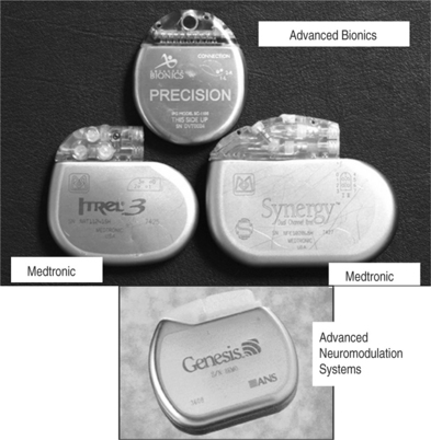
There are two main types of electrodes, the catheter-type (otherwise commonly referred to as ‘percutaneous’ leads) and the plate-type (otherwise commonly referred to as ‘laminotomy’ or ‘surgical’ leads) (Fig. 30.1). Percutaneous electrodes are commonly used both for trial stimulation or for permanent implantation. The most commonly used electrodes are either quadri- or octopolar. The general trend is to utilize one or two quadripolar electrodes for limb pain, and one or two octopolar electrodes for axial pain. A percutaneous electrode recently introduced by Advanced Bionics (Sylmar, CA) has 16 electrical contacts. The electrodes might be connected directly to the pulse generator/receiver, or they can be connected to an intermediate subcutaneous extension which, in turn, interfaces with the pulse generator/receiver.
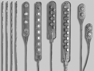
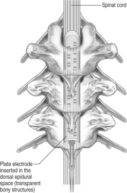
Plate-type electrodes require surgical implantation under direct vision (Fig. 30.2). The amount of actual bony removal varies and is often limited to a small portion of the lamina and spinous process. The simplest quadripolar plate electrode is the Medtronic Resume and Resume-TL, and the Advanced Neuromedulation Systems Lamitrode 4 (Medtronic Inc., Minneapolis, MN; Advanced Neuromedulation Systems, Plano, TX), with all four contacts arranged linearly in one paddle. The Medtronic Specify and the ANS Lamitrode 44 have eight contacts arranged in two parallel columns. Another electrode (ANS Peritrode) consists of two smaller paddles, each with two contacts; this configuration allows the surgeon to place the paddles in two different locations or with two different orientations and therefore offers a greater degree of flexibility. Plate electrodes with one or two columns of eight contacts are also available (ANS Lamitrode 88 and Lamitrode 8).
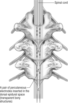
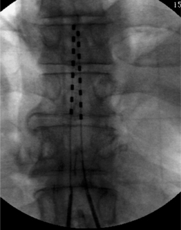
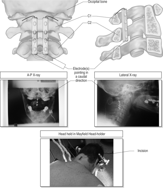
With modern technology, both types of electrodes are safe and effective ways of delivering electrical stimulation to the spinal cord. The percutaneous technique is appealing because it allows one to insert the electrode without muscle dissection and bony removal (Fig. 30.3). This is a substantial advantage when one wants to perform a trial stimulation to assess candidacy for a permanent implant. Percutaneously placed electrodes can also be advanced over several segments in the epidural space, thus allowing testing of several spinal cord levels. By inserting multiple parallel electrodes, various configuration matrices can be constructed that allow creating extremely focused electrical fields. Placement of percutaneous electrodes must be performed under fluoroscopic guidance (Fig. 30.4). This requires wearing heavy shielded garments and potentially exposes the implanting physician to non-negligible levels of radiation. The plate electrodes require open surgical intervention. Bony removal can be very limited. In the thoracic area the lower two-thirds of the spinous process and a small portion of the lamina usually have to be removed. In the cervical area, bony removal is often not necessary, and this is particularly true when placing electrodes at the C1–2 level. Most ‘laminotomy’ implants can be done through a small (1–1.5) skin incision. By advancing the electrode in a cephalad or caudal direction, one can explore at least three spinal levels in the thoracic and 4–5 in the cervical spine. (Fig. 30.4) Multiple arrays or different electrode configurations can be also constructed by utilizing more than one plate electrode. In the author’s experience, the main advantage of plate electrodes resides in their greater inherent stability in the dorsal epidural space and lesser propensity to migrate. Plate electrodes are the only option in case of previous spine surgery at the planned implant levels. The pattern of stimulation–induced paresthesiae provided by plate electrodes might be superior to the ones produced by the percutaneous electrodes. In a randomized, prospective study, North et al. proved that the performance of plate electrodes significantly exceeded that of percutaneous electrodes.10 Concordance of stimulation paresthesiae with pain was statistically better for plate electrodes. Plate electrodes are electrically more efficient. This is due to the fact that all the current is directed toward the dura instead of being dispersed circumferentially, as in the percutaneous electrodes. Plate electrodes therefore have a lower current requirement. Another advantage of plate electrodes with two columns of contacts lies in the fact that, unlike two parallel percutaneous electrodes, the relation among the electrical contacts is fixed and completely predictable. Some situations clearly command one of the two methods (i.e. a percutaneous system in the case of an outpatient percutaneous trial, or a plate electrode in the case of prior spine surgery). In most other situations, the choice is usually dictated by individual preferences and patterns of practice. A skilled implanter can usually achieve a similar stimulation matrix with either a plate or a percutaneous electrode. The differences between plate and percutaneous electrodes is likely to become more blurred with the development of miniaturized plate electrodes that can be introduced epidurally through a percutaneous device
WHAT STRUCTURES ARE BEING STIMULATED
The spinal canal contains several nervous and non-nervous structures that, when stimulated electrically, give rise to a variety of responses. The electrical properties of the intraspinal contents can be characterized as the ones of an nonhomogeneous conductor (Fig. 30.6) Knowledge of the different type of responses and their correlation with the underlying anatomical substrate is extremely important in implementing strategies for spinal cord stimulation.11,12
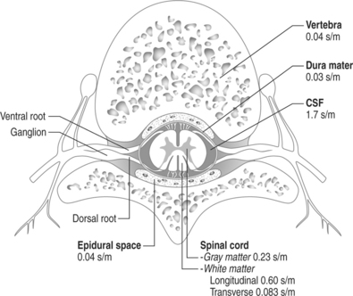
Fig. 30.6 Schematic drawing of the various intraspinal structures as they relate to spinal cord stimulation.
The width of the cerebrospinal (CSF) space is the most important factor in determining the stimulation parameters, particularly the perception and discomfort thresholds (Fig. 30.7). Dorsal root fibers in general have a lower stimulation threshold than dorsal column fibers and this is particularly evident with increasing thickness of the CSF layer. This is due in large part to the fact that dorsal root fibers have a very high conductivity at their entry into the spinal cord.
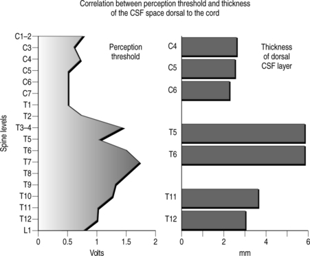
Activation of the dorsal columns usually occurs at a threshold that is at least 0.5–1.0 volt higher than the segmentary pathway. A thicker dorsal CSF space usually favors more selective activation of the segmentary sensory system as opposed to the dorsal column fibers. It is common to observe that, initially, systems are simultaneously activated, but after a few weeks the stimulation pattern is confined to a segmentary band. For this reason electrode placement in the upper thoracic spine (where the CSF space is the widest) seldom results in satisfactory long-term stimulation of the dorsal lemniscal pathway.
OPERATIVE TECHNIQUE
Percutaneous electrode placement
The fluoroscopy equipment is commonly utilized in both the anteroposterior (AP) and lateral planes at the time of needle insertion. This will allow monitoring of the depth of penetration and the laterality of the needle. The Tuohy needle is inserted with as shallow an angle as one possibly can obtain. While in the thoracic area this can be accomplished with either a midline or paramedian approach; in the upper lumbar area a paramedian approach is required. Besides lessening the risk of a dural puncture, a shallow trajectory greatly facilitates the subsequent insertion of the electrode in the epidural space. An excessively steep angle of entry of the electrode into the epidural space will also increase the risk of electrode fracture or dislodgment. A paramedian needle insertion is always more desirable, not only because it allows a more shallow angle of needle placement, but also because it avoids placing the electrode between two adjacent spinous processes. During lordotic extension of the trunk, the electrode can be pinched between the two spinous processes, leading to premature electrode fatigue and fracture.
Plate electrode placement
Patient positioning
In the semilateral position the patient lies comfortably in a bench-park type position, allowing the operative field to include the spine as well as the flank, abdomen or buttock for the pulse generator implant. If the pain is predominant on one side, the patient is asked to lie on the least affected side. In this position, airway management is safer than in the prone decubitus and the anesthesiologist feels more comfortable waking up and extubating the patient intraoperatively. One has to be aware that, because of variable degree of rotation of the body, 3-D spatial rapport and angles may vary; this can render 3-D visualization of the operated structures less intuitive. This problem is compounded in the cervical area since one has both rotation and flexion/extension of the spine.
Strategies at different spine levels
In the planning phase of the procedure, the implanting surgeon must be aware of the varying angulation of the spinous processes at the different spine levels. The surgeon must also be aware of the correlation between the various spine levels and the patterns of stimulation-induced paresthesiae.12,13
Implantation of the radio receiver/pulse generator
There are two types of spinal cord stimulation systems: (1) those with three parts, namely the electrode, an extension cable and the radio receiver/pulse generator, and (2) those with two parts only, namely the electrode and the radio receiver. In this latter situation, the electrode extension is long enough to connect directly to the radio receiver/pulse generator. The position of the pulse generator/receiver is crucial. If placed in an uncomfortable position, the unit will eventually have to be moved to a different location. The most common placement sites include the abdomen, the fat pad in the posterior iliac area, the infraclavicular area and the lateral chest wall area (Fig. 30.9).
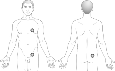
Posterior iliac area
This location is typically the most convenient region for the stimulating unit. The exact site of the placement is crucial, and it is at the level of the fat pad present laterally in the posterior iliac area, usually slightly below the iliac crest level. The main advantage of this location lies in the fact that, independently from the size of the patient or his/her body fat, the implant tends to remain stable without excessive motion. The subcutaneous tissue in that location is firm, and the presence of the underlying iliac wing acts as a stabilizing element. Even if the patient loses a large amount of body fat, the posterior iliac area does not change dramatically (unlike the abdominal adipose tissue). This area is also ideal for placement of radiofrequency receivers. The presence of the underlying iliac wing provides a firm background and allows the antenna to consistently make good contact with the implanted unit. The radio receiver/pulse must not be placed low in the buttock, since that location would make sitting extremely uncomfortable.
Intraoperative testing
If the procedure is performed under monitored or local anesthesia, the patient is woken up after the electrode(s) is placed in the desired position. The patient must be fully awake, cooperative, and with normal cognitive abilities before starting the intraoperative testing. Failure in this respect will inevitably result in incorrect positioning of the electrode. It is extremely important to assure that the patient is comfortable during the stimulation trial. When testing, the implanter must be aware of the different responses that stimulation of the various intraspinal structures will elicit. The strategy for electrode placement in both the transverse and longitudinal direction varies according to the pain topography and intraoperative elicited responses.12 As a general rule, one wants to achieve a complete paresthesia coverage of the painful area at the lowest possible stimulation threshold and with the least amount of extraneous stimulation.
If the implantation is performed under general anesthesia, one can rely on three factors.
1 Diascorides T. Goodyear J., editor. The Greek herbal of Diascorides. London: Oxford University Press, 1934.
2 Galen C. Tallmadge M., editor. De usu partium. Ithaca, NY: Cornell University Press, 1968.
3 Kellaway P. The part played by electric fish in the early history of bioelectricity and electrotherapy. Bull Hist Med. 1946;20:112-137.
4 Stillings D. A survey of the history of electrical stimulation for pain to 1900. Med Instrum. 1975;9:255-259.
5 Shealy CN, Mortimer JT, Reswick JB. Electrical inhibition of pain by stimulation of the dorsal columns. Preliminary clinical report. Anesth Anal Cur Res. 1967;46:489-491.
6 Hoppenstein R. Electrical stimulation of the ventral and dorsal columns of the spinal cord for relief of chronic intractable pain. Surg Neurol. 1975;4:187-194.
7 Larson SJ, Sances A, Cusick JF, et al. A comparison between anterior and posterior implant systems. Surg Neurol. 1975;4:180-186.
8 Lazorthes Y, Verdie JCL, Arbus L. Stimulation analgesique medullaire anterieure et posterieure par technique d’implantation percutanee. Acta Neurochir. 1978;40:253-276.
9 Waltz JM, Andreesen WH. Computerized percutaneous multi-level spinal cord stimulation in motor disorders. Appl Neurophys. 1982;45:73-92.
10 North RB, Kidd DH. A prospective randomized comparison of spinal cord stimulation electrode design. Acta of the 8th World Congress, The Pain Clinic. Tenerife, Spain, May 6–8 1998:p. 57.
11 Barolat G, Zeme S, Ketcik B. Multifactorial analysis of epidural spinal cord stimulation. Stereotactic Functional Neurosurg. 1991;56:77-103.
12 Barolat G, et al. Mapping of sensory responses to epidural stimulation of the intraspinal neural structures in man. J. Neurosurg. 1993;78:233-239.
13 Barolat G. Experience with 509 plate-electrodes implanted epidurally from C1 to L1. Stereotactic Functional Neurosurg. 1993;61:60-79.
[/level-membership-for-physical-medicine-and-rehabilitation-category][not-level-membership-for-physical-medicine-and-rehabilitation-category]
CHAPTER 30 Spinal Cord Stimulation for Chronic Pain Management Implantation Techniques
INTRODUCTION
The fact that electricity might beneficially affect painful conditions has been known since antiquity.1–4
Spinal cord stimulation (SCS) was introduced by Shealey in 1967.5 Initially, the electrodes were placed over the dorsal columns in the subarachnoid space through a laminectomy. Subsequently, the electrodes were implanted, always through a laminectomy, between the two layers of the dura or epidurally. Some authors demonstrated efficacy of the procedure even with electrodes implanted ventrally to the spinal cord.6–8 This did not prove to be a practical way of conducting spinal cord stimulation and was subsequently abandoned. In 1975, Dooley described percutaneous implantation of electrodes in the dorsal epidural space. Manufacturers involved in the early stages of SCS included Medtronic, Avery, Cordis, Clinical Technology Corporation. Initially, the stimulating systems were only radiofrequency (RF)-driven passive receivers. In the mi-1970s, Cordis introduced the first pulse generator powered by a lithium battery. This was then followed by the Itrel pulse generator manufactured by Medtronic. In the first stages, stimulation was delivered through a unipolar electrode. Subsequently, bipolar arrays were made available. Many different types of percutaneous and plate-type arrays were developed. In all of them, however, the contact combinations were hardwired, and could no be reprogrammed after the pulse generator was implanted. A very important advance stemmed by the collaboration of Joseph Waltz and the Neuromed company in the early 1980s; they produced the first percutaneous quadripolar electrode with contact combinations that could be reprogrammed noninvasively through the external transmitter.9,10
CURRENTLY AVAILABLE EQUIPMENT
Electrodes
There are two main types of electrodes, the catheter-type (otherwise commonly referred to as ‘percutaneous’ leads) and the plate-type (otherwise commonly referred to as ‘laminotomy’ or ‘surgical’ leads) (Fig. 30.1). Percutaneous electrodes are commonly used both for trial stimulation or for permanent implantation. The most commonly used electrodes are either quadri- or octopolar. The general trend is to utilize one or two quadripolar electrodes for limb pain, and one or two octopolar electrodes for axial pain. A percutaneous electrode recently introduced by Advanced Bionics (Sylmar, CA) has 16 electrical contacts. The electrodes might be connected directly to the pulse generator/receiver, or they can be connected to an intermediate subcutaneous extension which, in turn, interfaces with the pulse generator/receiver.
Plate-type electrodes require surgical implantation under direct vision (Fig. 30.2). The amount of actual bony removal varies and is often limited to a small portion of the lamina and spinous process. The simplest quadripolar plate electrode is the Medtronic Resume and Resume-TL, and the Advanced Neuromedulation Systems Lamitrode 4 (Medtronic Inc., Minneapolis, MN; Advanced Neuromedulation Systems, Plano, TX), with all four contacts arranged linearly in one paddle. The Medtronic Specify and the ANS Lamitrode 44 have eight contacts arranged in two parallel columns. Another electrode (ANS Peritrode) consists of two smaller paddles, each with two contacts; this configuration allows the surgeon to place the paddles in two different locations or with two different orientations and therefore offers a greater degree of flexibility. Plate electrodes with one or two columns of eight contacts are also available (ANS Lamitrode 88 and Lamitrode 8).
With modern technology, both types of electrodes are safe and effective ways of delivering electrical stimulation to the spinal cord. The percutaneous technique is appealing because it allows one to insert the electrode without muscle dissection and bony removal (Fig. 30.3). This is a substantial advantage when one wants to perform a trial stimulation to assess candidacy for a permanent implant. Percutaneously placed electrodes can also be advanced over several segments in the epidural space, thus allowing testing of several spinal cord levels. By inserting multiple parallel electrodes, various configuration matrices can be constructed that allow creating extremely focused electrical fields. Placement of percutaneous electrodes must be performed under fluoroscopic guidance (Fig. 30.4). This requires wearing heavy shielded garments and potentially exposes the implanting physician to non-negligible levels of radiation. The plate electrodes require open surgical intervention. Bony removal can be very limited. In the thoracic area the lower two-thirds of the spinous process and a small portion of the lamina usually have to be removed. In the cervical area, bony removal is often not necessary, and this is particularly true when placing electrodes at the C1–2 level. Most ‘laminotomy’ implants can be done through a small (1–1.5) skin incision. By advancing the electrode in a cephalad or caudal direction, one can explore at least three spinal levels in the thoracic and 4–5 in the cervical spine. (Fig. 30.4) Multiple arrays or different electrode configurations can be also constructed by utilizing more than one plate electrode. In the author’s experience, the main advantage of plate electrodes resides in their greater inherent stability in the dorsal epidural space and lesser propensity to migrate. Plate electrodes are the only option in case of previous spine surgery at the planned implant levels. The pattern of stimulation–induced paresthesiae provided by plate electrodes might be superior to the ones produced by the percutaneous electrodes. In a randomized, prospective study, North et al. proved that the performance of plate electrodes significantly exceeded that of percutaneous electrodes.10 Concordance of stimulation paresthesiae with pain was statistically better for plate electrodes. Plate electrodes are electrically more efficient. This is due to the fact that all the current is directed toward the dura instead of being dispersed circumferentially, as in the percutaneous electrodes. Plate electrodes therefore have a lower current requirement. Another advantage of plate electrodes with two columns of contacts lies in the fact that, unlike two parallel percutaneous electrodes, the relation among the electrical contacts is fixed and completely predictable. Some situations clearly command one of the two methods (i.e. a percutaneous system in the case of an outpatient percutaneous trial, or a plate electrode in the case of prior spine surgery). In most other situations, the choice is usually dictated by individual preferences and patterns of practice. A skilled implanter can usually achieve a similar stimulation matrix with either a plate or a percutaneous electrode. The differences between plate and percutaneous electrodes is likely to become more blurred with the development of miniaturized plate electrodes that can be introduced epidurally through a percutaneous device
WHAT STRUCTURES ARE BEING STIMULATED
The spinal canal contains several nervous and non-nervous structures that, when stimulated electrically, give rise to a variety of responses. The electrical properties of the intraspinal contents can be characterized as the ones of an nonhomogeneous conductor (Fig. 30.6) Knowledge of the different type of responses and their correlation with the underlying anatomical substrate is extremely important in implementing strategies for spinal cord stimulation.11,12
Fig. 30.6 Schematic drawing of the various intraspinal structures as they relate to spinal cord stimulation.
The width of the cerebrospinal (CSF) space is the most important factor in determining the stimulation parameters, particularly the perception and discomfort thresholds (Fig. 30.7). Dorsal root fibers in general have a lower stimulation threshold than dorsal column fibers and this is particularly evident with increasing thickness of the CSF layer. This is due in large part to the fact that dorsal root fibers have a very high conductivity at their entry into the spinal cord.
[/not-level-membership-for-physical-medicine-and-rehabilitation-category]
