Chapter 10 Scientific and Clinical Basis for Double-Bundle Anterior Cruciate Ligament Reconstruction in Primary and Revision Knees
INDICATIONS
Scientific Background: Anatomy and Biomechanics
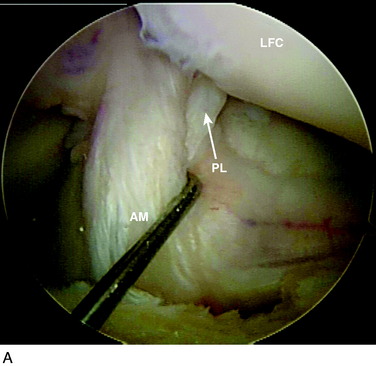
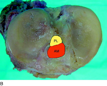
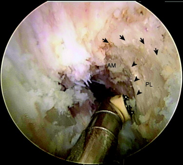
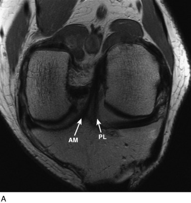
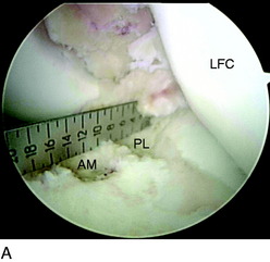
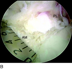
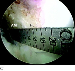
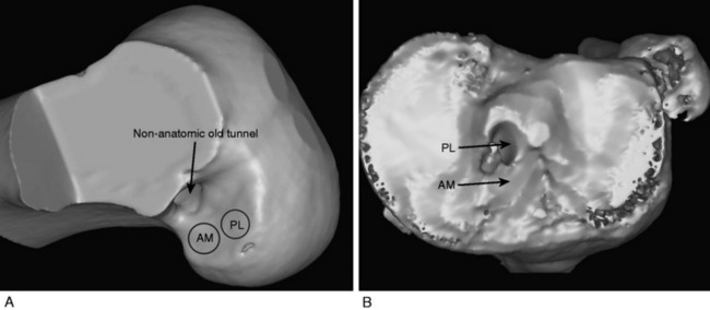
The anterior cruciate ligament (ACL) consists of dense connective tissue enveloped in a synovial membrane, which places the ligament in an intra-articular but extrasynovial position.2,5 It attaches proximally on the posterior aspect of the lateral femoral condyle (LFC) and runs in an oblique course distally through the intercondylar notch to insert between the medial and the lateral tibial spines. Many authors have studied the ACL bundle anatomy and reached a general consensus that the ACL consists of two bundles: an anteromedial (AM) bundle and a posterolateral (PL) bundle (Fig. 10-1A). The AM bundle is slightly larger in diameter than the PL bundle. The bundles are named for their relative positions on their tibial insertion sites4 (see Fig. 10-1B). Recently, the two-bundle anatomy was also verified in a fetal study by Ferretti and coworkers.6
The authors have studied the bony topography of the femoral attachment of ACL extensively. Using fetal specimens, cadavers, and in vivo arthroscopic observation, we have identified two osseous ridges that define the origins of the AM and PL bundles. The lateral intercondylar ridge runs proximal to distal through the entire ACL femoral attachment. With the knee in extension, no fibers of the ACL are attached anterior to this ridge. A second osseous ridge, the lateral bifurcate ridge, divides the femoral attachments of the AM and the PL bundles. It is important to note that when the knee is in full extension (anatomic position), the femoral origin of the AM bundle is located at the posterior and proximal portion of the lateral intercondylar wall, whereas the origin of the PL bundle is located slightly distally. The two bundles are parallel in extension. As the knee is flexed to 90°, which is the typical position during ACL reconstruction, the origins of the two bundles change from a vertical alignment to a horizontal alignment and the bundles cross.4 The lateral intercondylar ridge delineates the superior border of ACL femoral attachment (Fig. 10-2), whereas the lateral bifurcate ridge runs from superior to inferior and separates the femoral AM and PL attachments.
Biomechanically, the two bundles are not isometric throughout the range of knee motion. Generally, the AM bundle maintains at a constant level of tension throughout the range of motion, with some increase when the knee is flexed that reaches a maximum at 60°.7 The tension of the PL bundle is more variable because it tightens in knee extension and slackens in flexion past 30°. Thus, the AM and PL bundles have varying contributions to knee stability at different flexion angles. The AM bundle limits anteroposterior (AP) translation throughout knee motion, whereas the PL bundle plays an important role in limiting not only anterior tibial translation but also rotation.3,7,10
Biomechanical studies have emphasized the importance of both bundles in knee stability. Yagi and associates13 showed that double- bundle (DB) ACL reconstruction better restores knee biomechanics than single-bundle (SB) ACL reconstruction. The addition of a PL bundle produces in situ forces within each bundle that closely match the in situ forces found in a native ACL ligament. Tashman and colleagues11 studied the in vivo kinematics after ACL reconstruction with the use of high-speed stereoradiography. This study demonstrated that SB ACL reconstruction sufficiently restored AP tibial stability. An unexplained increase of 3° to 4° in adduction and external tibial rotation was reported. Zantop and coworkers15 showed that isolated transection of the AM bundle increased anterior tibial translation at 60° and 90° of knee flexion significantly, whereas isolated transection of the PL bundle significantly increased anterior tibial translation at 30° of flexion. In addition, PL bundle transection led to significantly increased rotation at 0° and 30° in response to a combined rotatory load when compared with the intact knee and the AM bundle–deficient knees. This study supports the concept that SB (AM bundle) reconstruction cannot restore native knee stability, particularly rotatory stability.
Revision Knees
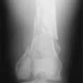
DB ACL reconstruction as a revision procedure may be indicated when an SB ACL reconstruction has failed owing to graft rupture or when an SB graft is intact but does not provide adequate stability. In the latter case, depending on the position of the original tunnels, the surgeon may either augment the intact SB graft with an additional graft or implant two new grafts. In the authors’ practice, patients frequently present with an intact SB graft but complain of clinical symptoms of instability and demonstrate a positive pivot shift on examination. In these cases, there is often a mismatch in the femoral and tibial tunnel placements. For example, the tibial tunnel occupies the position of the PL bundle and the femoral tunnel is located in a high position in the notch above the AM bundle attachment (Fig. 10-3). This pattern of mismatch is often a result of the transtibial technique for femoral tunnel preparation, in which the femoral tunnel position is dictated by the tibial tunnel position. The graft in this case may provide stability in the AP plane but does not provide adequate rotational stability and results in symptomatic instability.
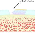
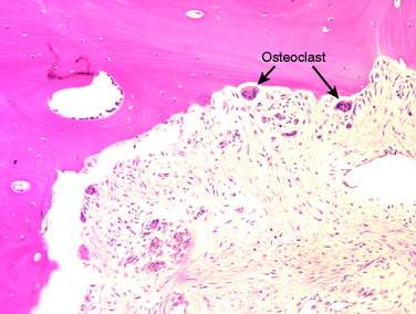
A nonanatomic tunnel placement, or tunnel mismatch, may lead to graft laxity and ultimate failure. In the laboratory, increased osteoclastic activity has been observed at the graft-bone interface in such mismatched tunnels (Fig. 10-4). When a graft is placed at a nonanatomic position relative to the native ACL, it experiences large tensile forces secondary to this abnormal position. These abnormal forces compromise biologic healing and ultimately may contribute to graft laxity and failure.
CLINICAL EVALUATION
Primary Knees
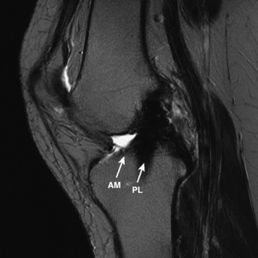
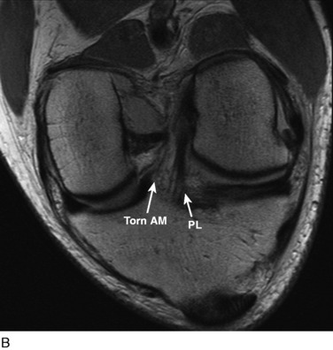
The other diagnostic study of importance is magnetic resonance imaging (MRI). At the authors’ center, a special protocol to study the ACL consists of a series of images in the plane of the two bundles of the ACL (Fig. 10-5A) in addition to the usual coronal, axial, and sagittal images. This provides improved visualization of the individual AM and PL bundles, allowing identification of individual bundle ruptures (see Fig. 10-5B) and the location of the rupture as either off the femur or the tibia or in mid-substance. In addition, assessment is performed of the condition of the other knee ligaments, menisci, cartilage, and bony structures.
Revision Knees
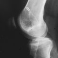
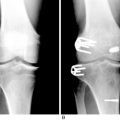
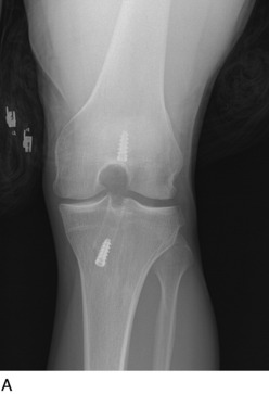
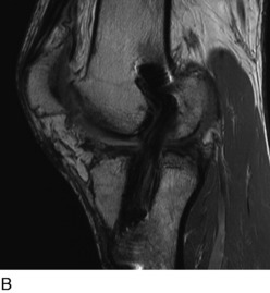
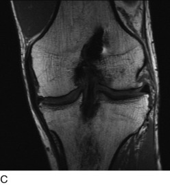
Radiographs are required to determine fixation methods used in the primary procedure (Fig. 10-6A). Joint space narrowing, osteochondral lesions, and tunnel width are identified. MRI is performed to determine whether the original graft is intact or ruptured, assess tunnel location and width (see Fig. 10-6B and C), and identify additional pathology involving the cartilage or menisci.
INTRAOPERATIVE EVALUATION
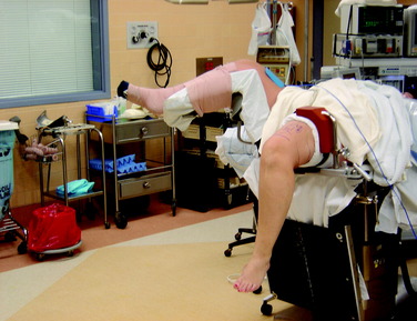
Once the patient is anesthetized with either a general or a spinal anesthetic, an examination under anesthesia is performed. Range of motion of both the injured and the noninjured knee is compared. The Lachman, pivot shift, and anterior drawer tests are performed to assess laxity under anesthesia. The operative limb is elevated for 3 minutes to allow exsanguination, and a tourniquet is then inflated to 350 mm Hg. The thigh is placed in a thigh holder and the bed is positioned with the distal portion flexed. The nonoperative leg is placed in a well-padded leg holder in the abducted position (Fig. 10-7). At this point, the operative lower extremity is prepared and draped with alcohol and povidone-iodine (Betadine).
Critical Points Operative Techniques
OPERATIVE TECHNIQUE
Primary Knees
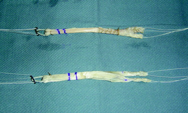
While the patient’s limb is being positioned, prepared, and draped, an assistant begins graft preparation. All allografts are obtained from a tissue bank certified by the American Association of Tissue Banks and inspected by the U.S. Food and Drug Administration (Lifenet, Virginia Beach, VA). The tibialis anterior grafts are thawed and rinsed on the back table in antibiotic solution. The allografts are frequently 24 to 30 cm in length and, when doubled over, provide 12- to 15-cm double-stranded grafts. The tendon allografts are trimmed of excess or loose tissue. When folded over, the AM graft is approximately 8 mm in diameter and the PL graft is approximately 7 mm (Fig. 10-8). Smaller-diameter grafts may be chosen in patients with small knees. The ends of the grafts are sutured using a baseball stitch with No. 2 Ti-Cron sutures for a length of 2.5 cm. An EndoButton CL (Smith & Nephew, Andover, MA) is applied to each graft, resulting in a double-stranded graft. The authors most commonly use a 15-mm-long loop. In cases in which patients refuse the use of allograft tissue, a hamstring autograft may be used. The hamstrings are prepared in the same fashion as the tibialis anterior allografts. The semitendinosus tendon is used for the AM bundle and the gracilis tendon is used for the PL bundle. Typically, the diameter of each hamstring autograft is smaller than that of the allograft tissue. Usually, the semitendinosus tendon graft measures 7 to 8 mm and the gracilis tendon graft, 5 to 6 mm. The authors prefer allograft tissue owing to consistency of size to restore the entire footprint of the AM and PL bundles of the ACL.
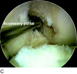
Arthroscopy is performed for diagnosis and treatment of associated injuries. Placing the portals in the correct location is critical for visualization and technical ease during the procedure. First, the anterolateral (AL) portal is established off the lateral edge of the patellar tendon at the level of the inferior pole of the patella. This portal is placed slightly higher than a traditional AL portal to obtain a broader view with the arthroscope. This portal is created with a No. 11 blade with the knee at 45° of flexion to avoid injuring the patella. An AM portal is required, along with an accessory anteromedial portal (AAM) (Fig. 10-9). The AM portal is placed along the medial border of the patellar tendon, inferior to the level of the AL portal. To establish the AAM portal, the arthroscope is placed in the AM portal, and an 18-gauge spinal needle is inserted medial and distal to this portal just above the medial meniscus. The trajectory of the needle aims to reach the center of the femoral footprint of the PL bundle. Care must be taken to ensure that the spinal needle does not pierce the medial meniscus and avoids contact with the medial femoral condyle because reamers must pass through this portal without damaging the medial femoral condyle. Once the needle is placed in the correct position, the AAM portal is made with a No. 11 blade. With the camera in the AL portal, a portion of the fat pad is débrided to allow visualization of the ACL insertions. Associated injuries are addressed before the ACL reconstruction.
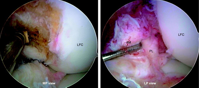
The rupture pattern of the ACL is evaluated by carefully probing the ligament. A meticulous, gentle dissection of the ACL bundles is performed using a thermal device (Arthrocare Corporation, Sunnyvale, CA), taking great care to preserve the soft tissue remnants at the tibial and femoral attachments and any intact bundle fibers. The determination is made whether one or both bundles are torn and whether the tear involves the femoral or tibial attachment. If one of the bundles is intact, it is preserved and augmented by reconstructing the ruptured bundle only. Preserving the soft tissue attachments allows anatomic identification of the proper locations for tunnel placement. Placing the arthroscope in the AM portal allows improved visualization of the femoral footprints. Furthermore, placement of the arthroscope in the AM portal makes notchplasty unnecessary in almost every case because of the excellent view obtained through this portal (Fig. 10-10).
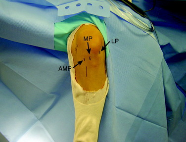
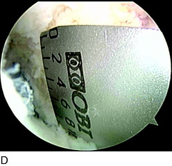
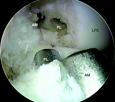
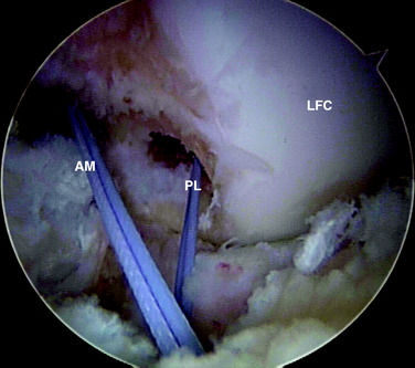
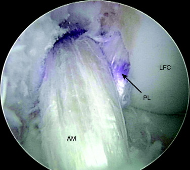
In chronic cases, the ACL rupture pattern and insertion sites may not be as visible compared with acute cases. A strong understanding of ACL anatomy is essential for accurate identification of the footprints of the bundles. The identification of two ridges, the lateral intercondylar ridge and the lateral bifurcate ridge previously described, assists to guide femoral tunnel placement (see Fig. 10-2). With the knee at 90° of flexion, the lateral intercondylar ridge (also known as the resident’s ridge) marks the superior border of the AM and PL bundles. No ACL tissue attaches above this ridge. The lateral bifurcate ridge is a bony prominence that divides the AM and PL insertions. When the knee is flexed 90°, the AM bundle femoral insertion is located posterior to the lateral bifurcate ridge and the PL bundle femoral footprint is located anterior to the lateral bifurcate ridge. Once identified, the femoral footprints of both the AM and the PL bundles are marked with the thermal device. A curved Steadman awl is used to create a small hole in the center of the femoral AM and PL footprints for subsequent guidewire placement. The tibial footprints are also marked by the thermal device. Both the tibial and the femoral footprints are measured for length and width to determine tunnel diameter and graft size (Fig. 10-11).
Next, the AM and PL tibial tunnels are prepared. A 3- to 4-cm skin incision is made over the AM surface of the tibia at the level of the tibial tubercle. The PL tibial tunnel is drilled first. With the arthroscope in the AL portal, the elbow ACL tibial drill guide is set at 45° and the tip of the drill guide is placed on the tibial footprint of the PL bundle via the AAM portal. The tibial PL bundle footprint is adjacent to the posterior root of the lateral meniscus and posterolateral to the AM bundle of the ACL (Fig. 10-12). On the tibial cortex, the tibial drill for the PL tunnel starts just anterior to the superficial medial collateral ligament fibers. Once the tibial drill guide is set, a 3.2-mm guidewire is passed into the base of the PL tibial footprint. The AM tibial tunnel is similarly drilled with the elbow ACL tibial drill guide set at 45° inserted through the AM portal. On the tibial cortex, the starting point for the AM bundle is midway between the PL starting point and the tibial tuberosity. There should be an adequate distance between these two pins to ensure sufficient bony bridge between the tunnels (Fig. 10-13). The AM and PL tibial tunnels are then overdrilled using a cannulated drill. The PL tunnel is usually accomplished with a 6-mm drill and the AM with a 7-mm drill. A curette is placed over the tip of the guidewire during reaming to protect the femoral articular cartilage. A dilator is used to widen the tunnels to the specific diameters, which are most commonly 8 mm for the AM tunnel and 7 mm for the PL tunnel.
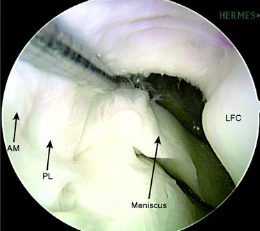
FIGURE 10-12 The PL bundle inserts on the tibia adjacent to the posterior horn attachment of the lateral meniscus.
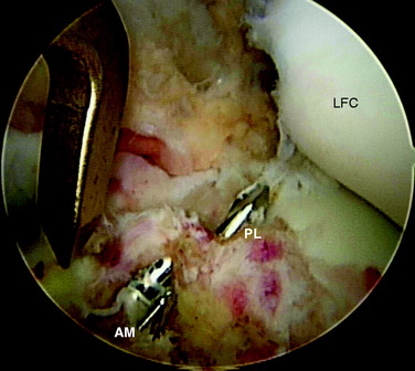
FIGURE 10-13 Guidewires for the AM and PL tibial tunnels are placed, centered in the insertions of the AM and PL bundles.
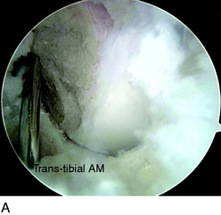
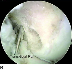
The femoral AM tunnel is the last tunnel to be drilled. The arthroscope is placed in the AM portal for this part of the procedure. First, a transtibial approach is attempted with a guidewire placed through the AM tibial tunnel (Fig. 10-14A). However, in some cases, the correct position for the AM femoral tunnel cannot be reached with this technique. Often, this places the guidewire too high and too far anterior on the medial wall of the lateral femoral condyle, outside of the anatomic footprint. In these cases, a transtibial technique through the PL tibial tunnel is attempted (see Fig. 10-14B). In some cases, the trajectory of the guidewire is still too high. When the center of the AM femoral footprint cannot be reached through either the AM or the PL tibial tunnel, the guidewire is placed through the AAM portal (see Fig. 10-14C). Usually, the knee must be flexed greater than 90° to position the pin appropriately in the center of the AM bundle attachment.
With the tip of the guidewire in place at the center of the AM femoral footprint, a cannulated acorn drill is inserted over the guidewire, drilling to a depth of 20 to 30 mm. A smaller depth is used when drilling through the AAM portal than transtibially owing to the shorter distance to the femoral cortex. The far cortex of the AM femoral tunnel is breached with a 4.5-mm EndoButton drill, and the depth gauge is used to measure the distance to the far cortex. The appropriate depth for the EndoButton to flip is calculated (the tunnel length minus 7 mm if a 15-mm loop is used), and the tunnel is reamed by hand to this depth with an 8-mm reamer. An assistant marks both the AM and the PL grafts with a marking pen at the appropriate distance from the EndoButton for the tunnel length. The final appearance of the tunnels after completion of preparation is shown in Figure 10-15.
The next step is graft passage, beginning with the PL graft. A Beath pin with a very long looped suture in the eyelet is passed through the AAM portal and out through the PL femoral tunnel. The looped suture is visualized intra-articularly and retrieved with an arthroscopic suture grasper through the PL tibial tunnel. This process is repeated for the AM graft, passing the Beath pin through whichever tunnel or portal was used to drill the AM femoral tunnel, and retrieving it through the AM tibial tunnel. The sutures from the Beath pin cross over each other with the knee in flexion (Fig. 10-16). Both Beath pins are passed before inserting the PL graft into the joint to protect it from injury. Subsequently, the PL graft is passed through the PL tibial tunnel into the PL femoral tunnel. Once the graft markings are seen, the EndoButton is flipped. During PL graft passage, the knee must be hyperflexed, just as it was during PL femoral tunnel preparation.
After passing the PL graft, the AM graft is passed retrograde and the EndoButton is flipped onto the lateral femoral cortex (Fig. 10-17). Preconditioning of the grafts is performed by flexing and extending the knee from 0° to 120°, approximately 20 to 30 times. Fixation on the tibial side is performed with bioabsorbable screws that are the same size in diameter as the grafts. We don’t actually measure the tension, but manually tension the graft and then confirm adequate tension by checking Lachman test and graft tension intraoperatively after fixation. The PL graft is fixed with the knee in extension, and the AM graft is fixed at 60° of flexion. After tibial fixation, a final arthroscopic inspection is performed to confirm the correct position and tension of the grafts. The surgeon verifies that there is no roof impingement or posterior cruciate ligament (PCL) impingement. Interestingly, these phenomena have not been observed in the setting of an anatomic DB ACL reconstruction.
Revision Knees
The AL, AM, and AAM portals are established as previously described. A careful arthroscopic examination is performed to assess the position and integrity of the graft. The graft may be intact but quite lax and stretched out, rendering it nonfunctional. If the graft is intact and functional, the location of the femoral and tibial tunnels must be judged. If the intact, functional graft is in an acceptable position for an AM or PL bundle, an augmentation procedure is performed in which the absent bundle is reconstructed, leaving the intact graft alone. Commonly, the tunnels for the intact graft are mismatched. Most often, the tibial tunnel is located in the area of the PL bundle attachment, and the femoral tunnel is placed anterior and superior to the AM bundle attachment (Fig. 10-18). In this case, the graft must be resected and new femoral tunnels established. Depending on the size of the original tibial tunnel, either one large tunnel for both AM and PL bundles or two separate tunnels may be used. If tunnel widening is excessive, the surgeon should consider bone-grafting the tunnel and staging the revision DB ACL reconstruction.
OTHER AUTHORS’ OUTCOMES
The literature contains few studies of outcomes after DB ACL reconstruction with techniques similar to those reported in this chapter. Most studies have short-term follow-up and employed different surgical techniques (e.g., use of a single tibial tunnel for both grafts along with two femoral tunnels). A few studies in the literature suggest improved rotational stability with DB techniques,1,8,9,12,14 but well-designed outcome studies with long-term follow-up are lacking.
1 Aglietti P., Giron F., Cuomo P., et al. Single- and double-incision double-bundle ACL reconstruction. Clin Orthop Relat Res. 2007;454:108-113.
2 Arnoczky S.P. Anatomy of the anterior cruciate ligament. Clin Orthop Relat Res. 1983;172:19-25.
2a Baer G.S., Shen W., Nozaki N., et al. Effect of knee flexion angle on tunnel length and articular cartilage damage during anatomic double-bundle ACL reconstruction. AANA Annual Meeting. Washington, DC; 2008
3 Buoncristiani A.M., Tjoumakaris F.P., Starman J.S., et al. Anatomic double-bundle anterior cruciate ligament reconstruction. Arthroscopy. 2006;22:1000-1006.
4 Chhabra A., Starman J.S., Ferretti M., et al. Anatomic, radiographic, biomechanical, and kinematic evaluation of the anterior cruciate ligament and its two functional bundles. J Bone Joint Surg Am. 2006;88(suppl 4):2-10.
4a Colvin A., Shen W., lrrgang J. The double bundle concept application for revision ACL surgery. Las Vegas: AAOS, 2009.
5 Dienst M., Burks R.T., Greis P.E. Anatomy and biomechanics of the anterior cruciate ligament. Orthop Clin North Am. 2002;33:605-620. v
6 Ferretti M., Levicoff E.A., Macpherson T.A., et al. The fetal anterior cruciate ligament: an anatomic and histologic study. Arthroscopy. 2007;23:278-283.
6a Fu F., Shen W., Okeke N., et al. Primary anatomic ACL double bundle reconstruction: 2 years follow-up of first 100 consecutive patients. Am J Sports Med. 2008;90:249-255.
7 Gabriel M.T., Wong E.K., Woo S.L., et al. Distribution of in situ forces in the anterior cruciate ligament in response to rotatory loads. J Orthop Res. 2004;22:85-89.
8 Jarvela T. Double-bundle versus single-bundle anterior cruciate ligament reconstruction: a prospective, randomized clinical study. Knee Surg Sports Traumatol Arthrosc. 2007;15:500-507.
9 Muneta T., Koga H., Mochizuki T., et al. A prospective randomized study of 4-strand semitendinosus tendon anterior cruciate ligament reconstruction comparing single-bundle and double-bundle techniques. Arthroscopy. 2007;23:618-628.
10 Sakane M., Fox R.J., Woo S.L., et al. In situ forces in the anterior cruciate ligament and its bundles in response to anterior tibial loads. J Orthop Res. 1997;15:285-293.
11 Tashman S., Collon D., Anderson K., et al. Abnormal rotational knee motion during running after anterior cruciate ligament reconstruction. Am J Sports Med. 2004;32:975-983.
12 Yagi M., Kuroda R., Nagamune K., et al. Double-bundle ACL reconstruction can improve rotational stability. Clin Orthop Relat Res. 2007;454:100-107.
13 Yagi M., Wong E.K., Kanamori A., et al. Biomechanical analysis of an anatomic anterior cruciate ligament reconstruction. Am J Sports Med. 2002;30:660-666.
14 Yasuda K., Kondo E., Ichiyama H., et al. Clinical evaluation of anatomic double-bundle anterior cruciate ligament reconstruction procedure using hamstring tendon grafts: comparisons among 3 different procedures. Arthroscopy. 2006;22:240-251.
15 Zantop T., Herbort M., Raschke M.J., et al. The role of the anteromedial and posterolateral bundles of the anterior cruciate ligament in anterior tibial translation and internal rotation. Am J Sports Med. 2007;35:223-227.