[level-membership-for-orthopaedics-category]
Chapter 16 Radiologic Aspects of Orthopedic Diseases
This chapter contains a radiologist’s viewpoints and suggestions regarding the interpretation of bone roentgenograms. It is hoped this will serve as a useful and practical guide for the busy physician. Principles concerning roentgenographic positioning, anatomy, and pathology are presented by using a regional anatomic approach. Additionally, the musculoskeletal applications of specialized radiologic modalities are discussed. This includes comments on nuclear medicine procedures, diagnostic ultrasound, arthrography, and angiography. Importantly, the imaging technologies of computed tomography (CT) and magnetic resonance imaging (MRI) as they pertain to the evaluation of orthopedic problems are detailed.
General Considerations of Roentgenographic Bone Anatomy
Before beginning a detailed discussion of regional roentgenographic anatomy and pathology, a consideration of pertinent radiologic bone anatomy is important. A bone can be evaluated according to its various components (Fig. 16-1).
APOPHYSIS
There are several apophyses throughout the skeletal system; the best example is the greater trochanter of the proximal portion of the femur. Apophyses do not contribute to bone growth but are considered accessory ossification centers. They tend to appear later than the epiphyses in normal bone development and form protrusions to which ligaments and tendons attach.
BONE VESSELS
There is only indirect evidence of the presence of blood vessels on roentgenograms, and it is the nutrient canals and foramina. They enter the medullary cavity by way of foramina, most often near the midshaft of a long bone, and result in radiolucent channels. When viewed on the roentgenogram, these channels can be confused with a fracture. Prominent nutrient canals frequently are seen in the diaphyses of the femur and tibia. Y-shaped nutrient canals occur in the midportion of the iliac bones of the pelvis and in the subspinous region of the scapulae.
Analytic Approach to Bone Changes
SPECIFIC PARAMETERS
Certain specific parameters of bone need careful attention. In the process of evaluating these, using a systematic approach can lead to a logical conclusion. Among the criteria to be analyzed are an increase or decrease in bone density, alterations in osseous texture (trabecular pattern), periosteal reactions, and the conditions of the cortex, endosteum, and medullary spongiosa. If any changes of these are observed, then the abnormality should be studied in terms of its size and configuration and the sharpness of its margins (transition zone). The specific bone involved and the position of the lesion within that bone (epiphysis, metaphysis, or diaphysis) should also be noted. For example, leukemia, metastatic neuroblastoma, a benign simple cyst, and Brodie’s abscess have a predilection for the metaphysis, whereas a chondroblastoma typically involves the epiphysis.
This is a simple, general outline, and many more particulars come into play. By developing this type of approach, the many clues offered will help to determine the nature of the pathologic process and place the lesion into a certain category (for example, benign, malignant, infectious, traumatic, or metabolic). Table 16-1 lists some of the specific characteristics of different bone lesions.
Table 16-1 General Characteristics of Different Bone Lesions
| Characteristics of benign bone lesions |
| Sclerotic margins (narrow transition zone) |
| Homogeneous periosteal reaction |
| Expansion of an intact cortex |
| Characteristics of solitary malignant bone lesions |
| Permeative or moth-eaten destruction (wide transition zone) |
| Irregular, sometimes spiculated periosteal reaction |
| Preferential metaphyseal location |
| Extraosseous extension with soft tissue mass and occasional fluffy calcifications |
| Characteristics of metastatic lesions |
| Absence of periosteal reaction |
| Moth-eaten destruction of medulla and cortex |
| Preferential diaphyseal location |
| Pathologic fractures |
| Multiple bone involvement |
| Characteristics of infection |
| Often irregular periosteal reaction, no spiculation |
| Bone destruction variable |
| Diaphyseal involvement, often involving long segments |
| Destruction of adjacent cartilage, crossing joints (majority of malignant neoplasms lack this ability) |
| Sequestration and involucrum formation |
PATTERNS OF BONE DESTRUCTION
TYPES OF PERIOSTEAL REACTIONS
When the outer periosteal membrane of bone is irritated, its constituent osteoblastic cells react by producing new bone. This new bone can take on either a solid or an interrupted appearance, and the specific form can assist in identifying the inciting cause (Table 16-2). Solid periosteal reactions are usually indicative of a benign process. The new bone is consistently uniform in density. As seen in Table 16-2, the thickness and marginal characteristics vary according to the precipitating factor.
| Types | Examples |
|---|---|
| Solid periosteal reaction | |
| Thin | Eosinophilic granuloma, osteoid osteoma |
| Thin undulating | Hypertrophic pulmonary osteoarthropathy |
| Dense undulating | Vascular |
| Dense elliptical (with destruction) osteoid osteoma | |
| Cloaking | Long-standing malignancy |
| Chronic infection | |
| Interrupted periosteal reaction | |
| Perpendicular (spiculated or sunburst) | Osteosarcoma, Ewing’s sarcoma, infection |
| Lamellated (onion skin) Osteosarcoma, | Ewing’s sarcoma, infection |
| Amorphous | Malignant tumors |
| Codman’s triangle | Malignant tumors, infection, hemorrhage |
* From Edeiken J, Hodes PJH: Roentgen diagnosis of diseases of bone, Baltimore, 1967, Williams & Wilkins. Used by permission.
The interrupted forms of periosteal reactions are more commonly found in malignant disease, although benign lesions such as infection are occasionally responsible. The classic spiculated or sunburst pattern of osteogenic sarcoma and the lamellated or onion skin, periosteal reaction of Ewing’s sarcoma come under this heading (see Table 16-2).
Regional Anatomic and Pathologic Roentgenography
CERVICAL SPINE
ROENTGENOGRAPHIC EXAMINATION
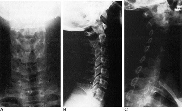
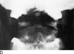
The standard roentgenographic views of the cervical spine include anteroposterior, lateral, and both posterior oblique views, as well as an open-mouth anteroposterior projection of the odontoid process and the first two cervical vertebral segments (Fig. 16-2). The majority of cervical spine studies are performed for the evaluation of trauma. In the more severely injured individual, the most important views are a cross-table horizontal beam lateral image and an anteroposterior supine film. By keeping patient movement to a minimum, potentially fatal spinal cord injury is prevented.
Dr. Don Weir of Saint Louis University developed the “pillar view” for better evaluation of the lateral articulating masses, the superior and inferior articulating facets, and their intervening joints. Moreover, this view brings into focus the anterior and posterior margins of the lamina (Fig. 16-3). The film is produced with the patient supine. Each side is done separately. The head is turned very slightly to one side, with the roentgenograph tube angled toward the feet 35 to 45 degrees and centered over the middle to lower vertebrae. The opposite side is then examined in a similar manner.
ROENTGENOGRAPHIC ANATOMY
A thorough understanding of the roentgenographic anatomy of the cervical spine is an absolute prerequisite to its proper evaluation. Each component of the individual vertebrae should be appraised separately on all views.
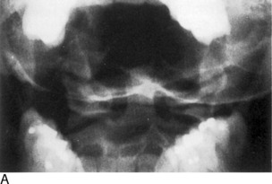
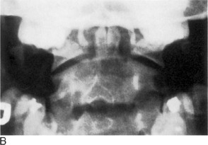
Odontoid View
Of the seven cervical vertebrae, the first two are anatomically distinct. The odontoid represents a superior extension of the body of C2 and is actually the vestigial body of C1. On the anteroposterior open-mouth film, the odontoid should be analyzed in terms of its position between the two lateral articulating masses of C1 (see Fig. 16-2, D). The spaces between the lateral edges of the odontoid and the medial borders of the C1 articulating masses should be equal. However, minor degrees of rotation can produce spurious inequality of these interval distances. How can this be determined? The alignment of the densities of the spinous processes of C1 and C2 can be seen. If the C2 spinous process is to one side or the other, then rotation is present.
Also on viewing the odontoid film, the transverse processes and lateral borders of the articulating masses of C1 and C2 should not be overlooked. The horizontal joints between the atlantoaxial articulating masses should be symmetric (see Fig. 16-2, D).
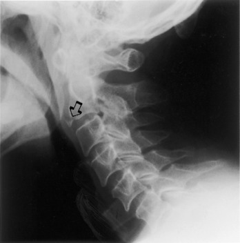
Confusing artifacts superimposed on the odontoid can be misleading and can result in misinterpretation of fractures of this structure. The inferior margin of the anterior or posterior arch of C1 can overlie the base of the odontoid and create a “Mach” effect, a radiolucent line produced by overlap of the edges of two bones. In a similar fashion, the space between the two incisor teeth may lay over the odontoid and yield an artifactual vertical cleft (Fig. 16-4).
It is not unusual for the odontoid process to be completely obscured by the base of the occipital bone if the head is held too far in extension. In such circumstances, have the view repeated with the patient’s head slightly more flexed.
Lateral View
Several important points must be remembered when viewing the lateral projection of the cervical spine (see Fig. 16-2, B). Alignments of the anterior and posterior borders of the vertebral bodies, alignment of the lateral articulating masses, and alignment of the spinolaminar line are studied. The latter is formed by the anterior margins of the spinous processes, which also describe the posterior surface of the spinal canal. The superior extension of this line is in direct alignment with the posterior margin of the foramen magnum.
The superior and inferior articulating facets ordinarily are well visualized on the lateral film. The posterior borders of the lateral articulating masses should form a straight line (see Fig. 16-2, B). If there is a slight offset, a facetal dislocation must be considered, although slight rotation can give a similar appearance. The view should be repeated if there is any confusion, and if the problem persists, CT scanning should be considered.
Oblique Views
The intervertebral foramina and surrounding elements, including the pedicles and uncinate processes, are the most important components demonstrated on the oblique views. The foramina on the right side are visualized on the left posterior oblique projection and those on the left on the right posterior oblique film (see Fig. 16-2, C).
TRAUMA
Recognition of an abnormal cervical spine should be a relatively simple task once normal roentgenographic anatomy has been mastered. After a traumatic lesion has been identified, the primary objective is the establishment of whether the condition is stable. The stability of a fracture is best determined by grouping the type of injury according to the mechanisms of trauma, which are outlined in Table 16-3. From this classification, a statement of the instability of the injury can be made (Table 16-4).
Table 16-3 Classification of Cervical Spine Injuries According to the Mechanisms of Injury*
| Flexion |
| Subluxation |
| Bilateral interfacetal dislocation |
| Simple wedge fracture |
| Flexion teardrop fractures |
| Clay-shoveler’s fracture |
| Flexion-rotation |
| Unilateral interfacetal dislocation |
| Vertical compression |
| Bursting fractures |
| Jefferson’s C1 |
| Bursting fractures, other levels |
| Extension |
| Posterior neural arch fracture |
| Extension teardrop fracture |
| Hangman’s fracture |
* From Harris JH Jr: Acute injuries of the spine, Semin Roentgenol 13:53–68, 1978. Used by permission.
Table 16-4 Classification of Cervical Spine Injuries Based on Stability*
| Stable |
| Subluxation |
| Simple wedge fracture |
| Unilateral interfacetal dislocation |
| Bursting fracture, except Jefferson’s fracture of C1 |
| Clay-shoveler’s fracture |
| Unstable |
| Bilateral interfacetal dislocation |
| Flexion teardrop fracture |
| Jefferson’s bursting fracture of C1 |
| Hangman’s fracture |
| Extension teardrop fracture, unstable in extension but stable in flexion |
* From Harris JH Jr: Acute injuries of the spine, Semin Roentgenol 13:53–68, 1978. Used by permission.
Flexion Injuries
There are a variety of flexion injuries, which are described below.
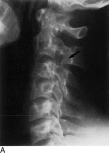
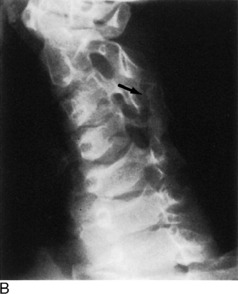
Subluxation
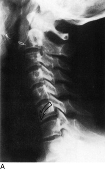
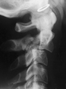
The roentgenographic findings in this stable lesion may be minimal, often requiring flexion and extension lateral views for confirmation. The body and posterior elements remain intact; that is, show no fracture. However, there is major soft tissue involvement. The interspinous and posterior longitudinal ligaments, as well as the interfacetal joint capsules, are disrupted at the affected level. This allows the involved vertebral body to rotate anteriorly about its anterior and inferior corner, along with upward and forward displacement of its inferior articular facet on the lower adjacent vertebra’s superior articular facet. The interspinous distance widens, and the inferior intervertebral disc space narrows anteriorly and widens posteriorly. These alterations are accentuated on the flexion film (Fig. 16-5). In children younger than 8 years, with the head held in flexion, the second cervical vertebra is normally displaced anteriorly over C3. This malalignment must not be mistaken for subluxation.
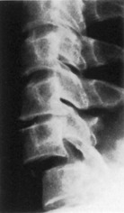
Clay-Shoveler’s Fracture
This lesion is named for the injury acquired by people in occupations that require heavy lifting. This injury consists of a fracture through the spinous process of either C6 or C7 (Fig. 16-6). There is no significant ligamentous damage, and therefore a stable condition exists. Because C7 is sometimes difficult to project on the lateral film, the fracture can be missed. A clue might be apparent on the frontal film, where an extraspinous process fragment is sometimes evident as the result of inferior displacement. An unfused apophysis of a spinous process must not be misinterpreted as a fracture (Fig. 16-7).
Flexion-Rotation Injuries
When the cervical spine is subjected to a rotational force in addition to flexion, a unilateral interfacetal dislocation may be observed (Fig. 16-8). An inferior articular facet of one body is displaced over the adjacent superior articular facet of the next inferior vertebra on one side only. The dislocated facet is more or less locked in place, but because of associated ligament damage, the lesion may be unstable; therefore, flexion and extension views are contraindicated. Oblique projections are most productive in identifying the displaced facet, but it may be suggested on the lateral film when the margins of the facets of a single vertebra do not superimpose on one another as the result of rotation. Additionally, a line drawn through the posterior borders of the bodies is offset at the level of the suspected injury.
Extension Injuries
Various extension injuries are described as follows.
Posterior Neural Arch Fractures
The neural arch of one vertebra may be compressed between the posterior elements of the two adjoining vertebrae during maximal forced extension. A unilateral or bilateral fracture may be sustained. If bilateral, the fragment can be displaced posteriorly, yet there will be no encroachment on the neural canal; thus, the situation is a stable one (Fig. 16-9).
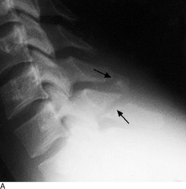
Extension Teardrop Fracture
Similar to the flexion variety, an extension teardrop fracture demonstrates a triangular-shaped fragment at the anterior-inferior margin of the body, most often involving C2, although other levels are affected (Fig. 16-10). However, the injury is not quite as severe, because there is no posterior involvement. When the neck is held in flexion, there is stability of the spine because the posterior ligament complex is intact. However, instability occurs during extension because the minor fragment remains attached to the anterior longitudinal ligament but not to the parent body.
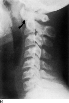
Hangman’s Fracture-Dislocation of C2
This lesion consists of vertical disruption of both pedicles of C2 and is created by flexion forces against the extended vertebrae. The body of C2 is thrust forward over C3, with concomitant rupture of both the anterior and the posterior longitudinal ligaments, giving rise to an unstable injury (Fig. 16-11).
Vertical Compression Fractures
A considerable force directed through the vertical axis of the spine (such as a large object falling on top of the head or a diving injury) can produce the so-called bursting fractures of the cervical vertebrae. The least common type is the Jefferson fracture of C1. The anterior and posterior aspects of the ring are fractured on both sides, with bilateral lateral displacement of the fragments. This unstable injury can be apparent on the open-mouth anteroposterior film but more reliably is distinguished on the lateral roentgenogram where the fractures are seen to extend through the posterior arches.
THORACIC AND LUMBAR SPINE
Roentgenographic Anatomy
Anteroposterior View
On the anteroposterior projection, the spinous processes provide another guide for the evaluation of alignment. Rarely, they may be absent because of aplasia or malignant or infectious destruction.
Oblique Views
Important anatomic features are introduced on the oblique views of the lumbar spine. These details have been covered more extensively in Chapter 8. On the left posterior oblique film (left side down against the film), the left half of the posterior neural arch elements, including the intervertebral foramina, are identified, whereas the right half of these components are viewed on the opposite projection. In the cervical spine, the reverse condition exists.
DEVELOPMENTAL VARIATIONS AND CONGENITAL ABNORMALITIES
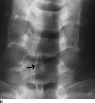
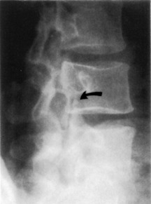
Confusing anatomic variations are seen in the developing and mature spine. In infancy, the vertebral bodies are egg-shaped on lateral view. The upper and lower anterior corners are beveled until the apophyseal vertebral rings appear about each end plate. They fuse with the body by the fifteenth year, but occasionally they remain ununited and, except for the presence of a complete sclerotic border, often are confused with a corner fracture (Fig. 16-12). These are sometimes referred to as limbus vertebrae.
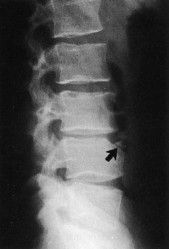
Fig. 16-12 An unfused ring apophysis of a lumbar vertebra as seen here can be confused with a fracture.
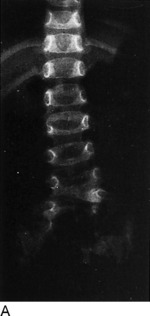
On the anteroposterior film, a vertical radiolucent cleft is seen superimposing on the vertebral bodies (Fig. 16-13). This represents the normal uncalcified portion of the posterior neural arch and spinous process and is not to be confused with spina bifida. At approximately 3 to 5 years of age, these will ossify and fuse. When they do fail to fuse completely, the cleft persists as a spina bifida occulta. This can occur anywhere in the spine, but is most common at L5. These are of no clinical importance.
Hypoplasia of the vertebrae, fusion or block vertebrae, and hemivertebrae constitute a few of the other possible spinal anomalies (Fig. 16-14).
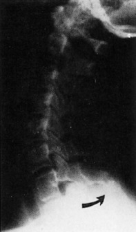
TRAUMA
Another important traumatic lesion, particularly of the lumbar spine, that can be easily overlooked is the transverse process fracture (Fig. 16-15). The importance of its recognition rests with the fact of frequently related renal injury. It is important not to mistakenly call the unfused apophysis of the transverse process a fracture.
A seldom-seen injury to the lumbar vertebrae is the Chance fracture (Fig. 16-16). An extreme flexion force, often related to seat belt injuries, causes a fracture through the spinous process, across the neural arch or lamina, and into the posterosuperior aspect of the vertebral body. An isolated fracture of the spinous process is uncommon in the thoracic and lumbar regions.
One more pitfall to watch for in the assessment of spinal trauma is the unfused ossification center of the articular facets, which can resemble a fracture (Fig. 16-17). In evaluating the posterior elements, it is important to keep in mind the entities of spondylolysis and spondylolisthesis (see Chapter 8).
TUMORS
Hemangioma
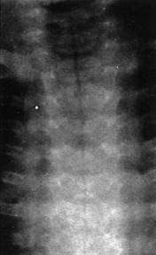
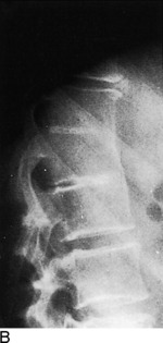
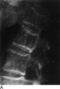
Hemangiomas of the vertebral body may be the most common benign tumor, although few have been documented pathologically. Typically, their appearance is that of increased vertical trabeculations producing a somewhat striated pattern (Fig. 16-18). They should not be confused with Paget’s disease or osteoblastic metastasis.
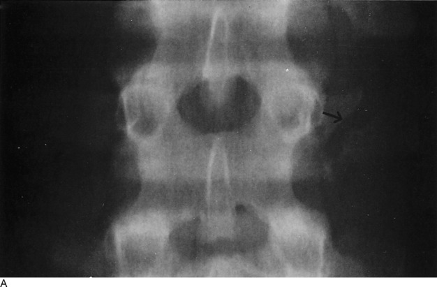
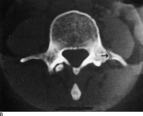
Aneurysmal Bone Cyst
Of the benign tumors of the spine, aneurysmal bone cysts are possibly the next most frequent after hemangiomas. They are more commonly found in the extremities, especially the distal portion of the femur. In the spine, they tend to involve the posterior elements as well as the body. Possessing a thin shell of peripheral bone, they are expansile and cystic in nature. Roentgenographically, a malignant appearance can be seen with a predominant cystic pattern. Unlike other tumors, benign and malignant alike, aneurysmal bone cysts have the unique capability of crossing over the cartilaginous disc space to involve adjacent vertebrae. A malignant chordoma also has this potential.
Hodgkin’s Lymphoma
Hodgkin’s disease can occasionally be seen within the bony spine and may present as an osteolytic or osteoblastic alteration or a combination of the two. However, more commonly, paraaortic lymph node involvement with lymphoma produces erosive changes of the vertebral cortical margins.
INFECTION
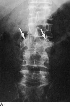
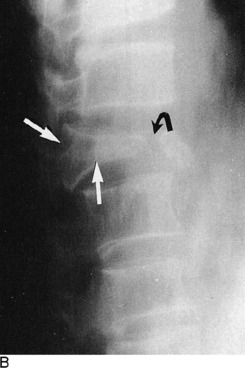
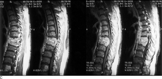
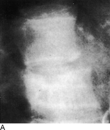
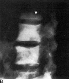
In both pyogenic discitis and vertebral osteomyelitis, the earliest roentgenographic findings may be joint space narrowing. Depending on the aggressiveness of the offending bacteria and the time of institution of therapy, the surrounding bone shows varying degrees of demineralization brought on by hyperemia. The end plates then demonstrate progressive loss of continuity with irregular destruction and focal areas of subchondral reactive sclerosis. Extension into the posterior third of the body, then into the dorsal appendages, as well as into the adjoining vertebrae, may occur. The body may eventually collapse. Some degree of surrounding soft tissue swelling is invariably present and detectable on roentgenograms and corroborated on MRI (Fig. 16-19).
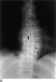
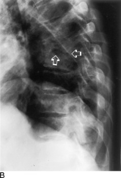
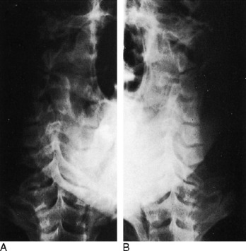
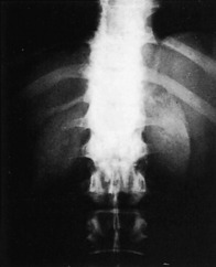
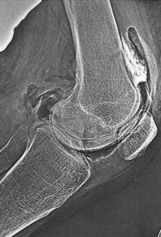
Because of its insidious and chronic nature, the spinal lesions are usually advanced when first examined roentgenographically, although this is not always the situation. An occasionally prominent feature is a large paravertebral soft tissue mass that constitutes the abscess. In later phases, there may be extensive calcification within this mass (Fig. 16-20). The bony structures show a decrease in density, and there is narrowing of one or more of the disc spaces. The margins of the end plates manifest irregular destruction, and a mottled sclerotic and lytic appearance extends into the bodies, which display varying degrees of compression.
SPINAL ARTHRITIS
Arthroplasty of spondylosis of the spinal column most commonly is degenerative in nature with the formation of hypertrophic bony spurs. These osteophytes are formed by recurrent stimulation of wear and tear factors, and are predominantly located along the end-plate margins of the vertebral bodies. When they bridge the interspaces and fuse, such spurs are described as syndesmophytes, which can more often be identified in specific forms of arthritis, such as diffuse idiopathic skeletal hyperostosis (DISH; Fig. 16-21).
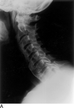
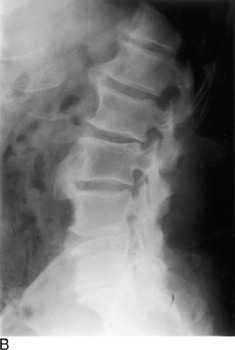
Ossification of the anterior longitudinal ligament of the spine is characteristic of ankylosing spondylitis (Marie–Strümpell disease). Psoriatic arthritis, Reiter disease, and other autoimmune diseases (including inflammatory bowel diseases) may lead to exuberant osteophyte formation.
PAGET’S DISEASE
One of the distinctive roentgenographic characteristics of spinal Paget’s disease is that the disorder involves the entire vertebra—the body and all of the posterior elements, including the transverse and spinous processes (Fig. 16-22). Generally, there is an increase in density produced by a thickened trabeculae. A picture frame appearance can be imparted to the body, the result of a dense peripheral margin of thickened cortex. Furthermore, there is an actual increase in volume of the entire vertebra. This finding, along with total vertebral involvement, distinguishes Paget’s disease from an osteoblastic metastasis.
THE SHOULDER
ROENTGENOGRAPHIC EXAMINATION
In the majority of cases, a complete and optimal roentgenographic study of the shoulder girdle needs only include upright—standing or sitting—anteroposterior views with the humerus in internal and external rotation. These two projections usually permit adequate evaluation of the bony structures constituting the shoulder. In the uncooperative child or severely traumatized patient, these films may be obtained while the patient is in the supine position. On these roentgenograms, the complete clavicle should be visualized in addition to the entirety of the scapula and at least the proximal third of the humerus. Special attention should be given to the alignments of the glenohumeral, acromioclavicular, coracoclavicular, and sternoclavicular joints. The tuberosities of the humeral head and its articular surface should be specifically scrutinized. The acromium and coracoid processes, in addition to the borders and flat surfaces of the scapula, require attention.
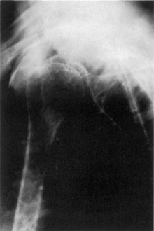
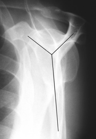
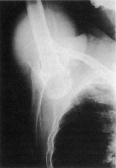
When there is suspicion of a fracture involving the shaft of the humerus below the neck, in addition to an anteroposterior view, a transthoracic lateral projection is necessary for evaluation of alignment (Fig. 16-23). The glenohumeral relationship can also be accessed with proper exposure, but because of superimposed ribs, fractures above the neck are difficult to see. Instead, a transscapular study is more helpful (Fig. 16-24). This view is obtained by having the patient face the film at an angle of 45 degrees with the affected side toward the film holder. The resultant picture forms a Y where the acromium, coracoid, and scapular body intersect. The humeral head will be superimposed on the Y. This is useful not only for fractures but also for posterior dislocations. This transscapular examination is always used when studying the scapula, in addition to the routine anteroposterior roentgenogram. CT or MRI imaging, particularly the latter, can provide additional valuable information especially regarding soft tissue involvement. The multiplanar capabilities of these imaging modalities augments visualization of gross pathologic findings.
Posterior shoulder dislocations are notorious for their ability to avoid detection on the standard anteroposterior views; they are frequently associated with seizure disorders. The tangential projection is an excellent means for detecting the abnormality. This is performed by angling the roentgen tube approximately 30 degrees so that the central ray passes tangentially across the glenoid articular surface. In this manner, the glenohumeral relationship is much better defined than on the conventional straight anteroposterior view.
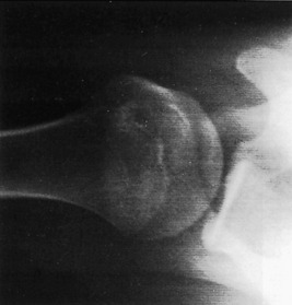
The axillary film also provides another perspective of the shoulder anatomy (Fig. 16-25). The acromium, coracoid, glenohumeral joint, and humeral head are viewed in a different plane. By holding the film against the top of the shoulder, the picture is produced by abducting the arm and centering the roentgen tube through the axilla. The study requires a special “grid” cassette for the film. It is helpful in determining the presence of a humeral head displacement, but it is not recommended when a dislocation has just been reduced, because the required abduction may reluxate the joint.
A more difficult area to examine roentgenographically is the sternoclavicular joint. Because of bony superimposition, CT may be required, but because this is not universally available, both oblique and lateral views may suffice. However, if these attempts are unsuccessful, the patient can be positioned prone. The roentgen tube is then centered through the sternoclavicular joints and angled toward the head at a 35-degree tilt.
ROENTGENOGRAPHIC ANATOMY AND DEVELOPMENTAL VARIATIONS
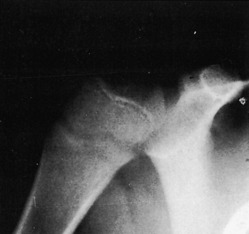
A considerable degree of confusion can be created by the ossification centers of the shoulder. The proximal humeral epiphysis does not become visible, as a rule, until the fourth to eighth month of life. There are two, occasionally three, separate centers. By the age of 20, the proximal epiphysis fuses to the shaft of the humerus. Before complete closure of the epiphyseal suture, the lucent line has a peculiar angulated appearance (Fig. 16-26). Overlap of the suture line occurs no matter what projection is used and consequently produces an image simulating a fracture.
TRAUMA
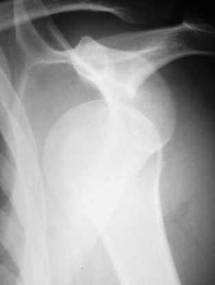
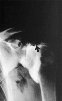
Of all the joints in the body, the shoulder is the most frequent site of dislocations. More than 97% are anterior and can be described as subglenoid or subcoracoid, depending on the location of the humeral head. Invariably, this form of dislocation can be visualized by a single anteroposterior roentgenogram (Fig. 16-27). Whenever a dislocation occurs, it is not unusual to have an associated fracture; this should be searched for on the film. With an anterior dislocation, a fracture of the greater tuberosity may exist; the lesser tuberosity is vulnerable in posterior dislocations. The lower glenoid margin is also susceptible in either type of dislocation. An infraction of the articular cartilage without a visible fracture is also possible in dislocations and may require MRI to demonstrate.
With chronic recurring anterior dislocations, a defect becomes apparent along the superolateral aspect of the humeral head. This cortical infraction, present because of impaction against the anteroinferior rim of the glenoid, is commonly referred to as Hill–Sachs deformity. This abnormality is usually best demonstrated on an internally rotated anteroposterior view (Fig. 16-28).
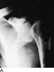
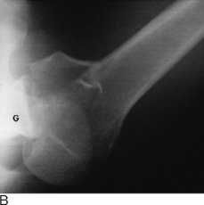
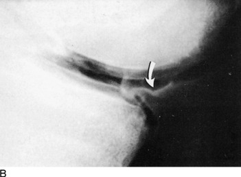
The less frequent posterior dislocation is much more difficult to visualize roentgenographically. The problem arises because the humeral head on the standard anteroposterior projections shows no apparent separation from the glenoid fossa when in fact it is separated. The posterolateral orientation of the glenoid articular surface accounts for this to some extent. Ordinarily, in the normal shoulder the head of the humerus overlaps about three fourths of the glenoid fossa. When it becomes posteriorly dislocated because of lateral displacement of the head, this overlap is less, but the change may be very subtle. This perplexing situation can usually be solved by using the 30-degree tangential view, the axillary projection, or the transscapular film (Fig. 16-29). With recurrent posterior dislocations of the shoulder, a defect of the inferoposterior cartilagenous labrum may not be visible by stand-ard radiography. This is termed a Bankart lesion, which can be diagnosed by MRI or CT arthography.
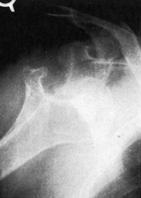
A very rare form of dislocation of the shoulder joint is luxatio erecta, a condition where the humeral head is located under the glenoid rim and the humeral shaft is directed above the head in fixed abduction (Fig. 16-30). A lateral fall on an elevated arm produces such an abnormality. The acromium process of the scapula acts as a fulcrum pushing the head of the humerus down and out of the glenohumeral joint. The dynamics of the applied forces can result in a fracture of the acromium, the lower lip of the glenoid, or the greater tuberosity of the humerus. Often, there is an associated tear of the rotator cuff.
Transverse subcapital fractures of the surgical neck along with avulsions of the greater tuberosity are the most commonly encountered injuries to the shoulder. A fracture-displacement of the ununited epiphysis creates a more difficult diagnostic challenge. The normal epiphyseal line itself, as already mentioned, makes interpretation troublesome. The normal epiphysis has a uniform width and dense margins, whereas a fracture demonstrates varying thickness with a sharp, nonsclerotic edge. Often, there is impaction or distraction of the fragments causing some degree of overlapping, which makes the diagnosis somewhat simpler. Of course, if the presence of an abnormality is uncertain or indeterminate, an accurate comparison with the opposite uninjured shoulder should be performed.
TUMOR
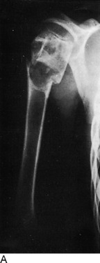
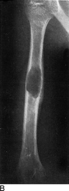
The proximal aspect of the humerus is a relatively common location for a benign solitary cyst, which may appear as either simple or multiloculated (Fig. 16-31). Such cysts are found within the metaphysis and exhibit destruction of the medullary spongiosa with more or less expansion of the bone. Thinning of the cortex can attain paper thickness, and pathologic fractures are a very common event, even in the absence of significant trauma. When initially discovered, the cysts extend to the epiphyseal line but do not involve the growth center itself. When followed serially until fusion of the epiphysis, the cyst appears to “migrate” toward the middle of the shaft as growth of the bone ends progresses.
Primary malignant tumors of the shoulder are a rarity and are often of the sarcomatous variety. Osteogenic sarcoma as well as the round-cell tumors, Ewing’s sarcoma, and reticulum cell sarcoma have already been described. Secondary metastatic disease is much more prevalent than primary lesions, particularly disease of the proximal aspect of the humerus. As with cysts, pathologic fractures frequently accompany these malignant changes.
THE ELBOW
ROENTGENOGRAPHIC ANATOMY
Before considering specific elbow lesions, pertinent roentgenographic anatomy of the elbow must be considered. Evaluating the different bony landmarks and their relationships can prove extremely useful. In children, a great deal of confusion arises because of the ossification sequence of the growth centers. The capitellum, trochlea, and the medial and lateral epicondyles compose the centers of the distal portion of the humerus. In addition, the elbow contains the olecranon apophysis and the radial head epiphysis (Fig. 16-32).
The first of the distal humeral epiphyses to appear is the capitellum, which develops by the age of 2 years. At about 6 years of age, the medial epicondylar center becomes visible. Next to become evident is the trochlea at 10 years of age, and finally, the lateral epicondyle appears near the twelfth year of life.
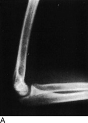
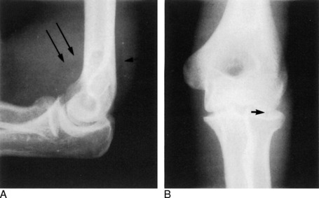
Contained within these recesses are the fat pads, fairly sensitive indicators of the presence of a distended joint capsule. In the normal elbow, assuming a true lateral flexion film is obtained, the posterior fat pad is not visible. The anterior fat pad forms a slim, triangular lucency adjacent to the anterior humeral cortex. With the presence of joint fluid, such as blood resulting from an intraarticular fracture, one or both of these fat pads will be elevated. The so-called fat-pad sign is not specific and may be seen in conditions other than trauma, such as pyarthrosis or rheumatoid arthritis. In cases of injury, a positive fat-pad sign should be searched for from the beginning and, if found, should initiate further investigation for an occult fracture, particularly of the radial head (Fig. 16-33). Oblique views may be required, and if necessary, a repeat examination may be done in 7 to 10 days, at which time a fracture should be apparent. On occasion, no fracture will be found, and the distended joint may be on the basis of a cartilage infraction or capsular tear. In adults, an intraarticular fracture may be present in the absence of fat-pad elevation, but in children it is a more reliable indicator, being found in approximately 90% of elbow fractures (Rogers, 1978).
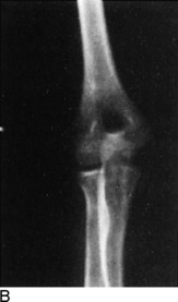
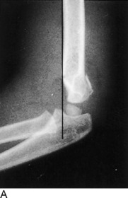
Two other helpful relationships are of assistance when evaluating normal elbow anatomy. The first is the anterior humeral line. On the lateral film, a line is drawn along the anterior margin of the humeral shaft and extended through the joint. If the capitellum is divided into equal thirds, this line normally passes through the middle third. It is a simple and useful index in analyzing the normal 140-degree angle that the articular structures form with the shaft of the humerus. This easy maneuver often alerts the physician to a subtle transcondylar fracture in children: the line extends through or anterior to the anterior third division of the capitellum (Fig. 16-34).
TRAUMA
A supracondylar fracture should more aptly be called a transcondylar fracture because it extends across the condyles and is seen through the coronoid and olecranon fossae (see Fig. 16-34). The anterior humeral line indicates posterior displacement of the distal fragment when the fracture is complete, which is seen in 75% of cases. However, the remainder are incomplete, and visualizing the fracture line may be impossible. Almost always the posterior fat pad is elevated.
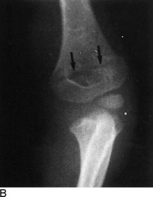
Little Leaguer’s elbow, discussed in Chapter 6, describes an injury in which the medial epicondyle is separated. Ordinarily, the avulsed center is best identified on the anteroposterior film, often lying adjacent to the capitellum. In rare instances, the fragment may become displaced into the medial joint space, where it can simulate the trochlear ossification center before its actual appearance.
The coronoid process is frequently avulsed in posterior dislocations of the elbow and is impacted against the trochlea. Whenever an elbow dislocation occurs, the radius and ulna are displaced lateral and posterior to the humerus in almost all instances. In children, when the radius and ulna are medial to the humerus, there is not a dislocation but rather a fracture through the entire distal humeral epiphysis. This is extremely important to recognize, because treatment of the two are entirely different.
THE WRIST AND HAND
ROENTGENOGRAPHIC ANATOMY, DEVELOPMENTAL VARIATIONS, AND PATHOLOGY OF THE INDIVIDUAL BONES
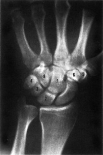
The carpus is composed of a proximal and distal row of four bones each. To remember their names, the infamous mnemonic of “Tilly’s pants” still applies, but a picture is sometimes more than words can describe (Fig. 16-36).
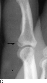
Small, well-defined, round to oval areas of increased density are often identified in any of the carpal bones, metacarpals, and phalanges. They represent clinically insignificant bone islands (Fig. 16-35).
Tiny, rounded lucencies with well-delineated sclerotic margins coincide with vascular channels, but cystlike areas are also frequently encountered within or along the cortical borders of any of the hand or wrist bones, especially the carpal bones. These may be the result of medullary fibrosis or hemorrhagic cysts. When related to the articular cortex, these cysts are the result of synovial herniation in osteoarthritis when the other classic signs of this disease are present. Erosive cysts at the justaarticular margins are diagnostic of rheumatoid arthritis.
In the forthcoming discussion, all of the individual wrist and hand bones are considered separately.
Navicular
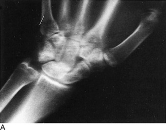
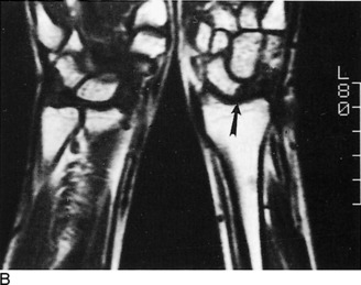
Transverse fractures of the navicular most often involve the midportion, but any segment can be involved, including avulsions of the lateral tubercle. Dislocations of the navicular are discussed in the following section with the lunate bone. In recent years, these posttraumatic findings of navicular fractures and complications have been readily assessed by means of MRI (Fig. 16-37).
Lunate
Around the fourth to fifth year of life, the lunate bone becomes visible by ossification. Like the navicular, it may develop from two separate centers; if these centers fail to fuse, complete or partial fracturelike lines result.
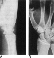
One of the most notable pathologic changes affecting the carpal lunate is Kienböck’s aseptic necrosis. This form of osteochondritis is described in more detail in Chapter 7. The carpal lunate is infrequently fractured but is involved in one of the more important traumatic lesions of the wrist—dislocations. Three important types of wrist dislocations have been described. The first is a transnavicular perilunate dislocation (Fig. 16-38). In this condition, there is a fracture at the midnavicular. The proximal pole fragment and the lunate maintain their normal relationship with the radial articulation, but the distal pole segment of the navicular bone and the remaining carpal bones become displaced posteriorly.

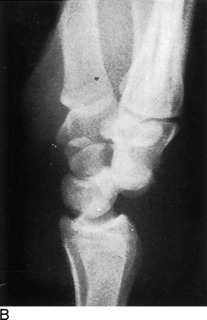
The third type of carpal displacement is a pure lunate dislocation (Fig. 16-39). The articular relationship between the lunate and the capitate is disrupted. The lunate rotates anteriorly, which is best appreciated on the lateral view. On the anteroposterior film, the lunate takes on a somewhat triangular appearance, which should alert the clinician to this abnormality.
Triquetrum
The triquetrum, or triangular bone, appearing between the second to third year, probably is the second most frequently fractured bone of the carpus. This usually consists of a posterior chip fracture, identified on the lateral roentgenogram, and is usually of no clinical importance.
Metacarpals and Phalanges
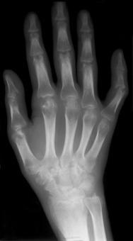
When assessing the metacarpal bones, there are several important anatomic features to be considered (Fig. 16-40). The epiphysis of the first metacarpal bone (the thumb) is located proximally, whereas the growth center occupies the distal aspect of the remaining four metacarpals. This property is consequential in terms of an examination made for assessing the presence of fractures in the growing patient. But, as is usual, there is always some variation to confuse the issue. On occasion, the clinician may see what appear to be epiphyses involving the distal first metacarpal or the proximal second metacarpal; these are appropriately termed pseudoepiphyses.
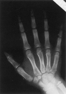
Fig. 16-40 Normal hand bones of a 9-year-old child. Note the position of the epiphyses of the metacarpal bones.
The appearance of the phalanges, particularly the terminal ones, is extremely variable, and the variants, for all practical purposes, should be considered normal. The ungual tuberosity or tuft of the distal phalanx can have many shapes and sizes, yet a number of disease processes may alter them considerably. Deformity and erosive changes of the tufts are seen in scleroderma, sarcoidosis, psoriasis, and leprosy.
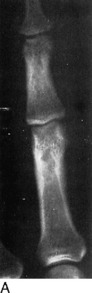
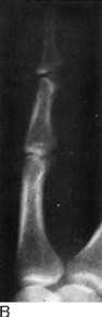
Of all of the fractures involving the fingers, those of the tuft are probably the most common and may be avulsion types or comminuted. When analyzing the injured finger, the importance of obtaining a true lateral view, in addition to anteroposterior and oblique projections, cannot be stressed too much (Fig. 16-41). This becomes particularly apparent in cases of volar plate injuries. A fragment of bone is avulsed from the palmar aspect at the base of the middle phalanx and involves the proximal interphalangeal joint. The result of hyperextension forces, the fragment may be obscured on all but the lateral film.
Rheumatoid arthritis produces distinctive transformations in the joints of the hand and wrist (Fig. 16-42). The earlier roentgenographic finding may be periarticular soft tissue swelling. Later, demineralization about the joint with slight widening of the joint space will be noted—the result of inflammatory hyperemia with intraarticular fluid and synovial thickening. This progresses to juxtaarticular cortical erosions, which are related to synovial hypertrophy and pannus formation. Eventually, the joint space becomes narrowed, and classic ulnar subluxations occur. Unlike degenerative osteoarthritis, there is no reactive spur production in rheumatoid arthritis.
THE PELVIS AND HIPS
ROENTGENOGRAPHIC ANATOMY AND DEVELOPMENTAL VARIATIONS
Small centers of ossification arise from the anterior inferior iliac spines by the thirteenth year and fuse 2 to 3 years later. Athletes are prone to avulsion of these centers, and this should be looked for when there is localized pain in a sports-related injury (see Chapter 15). Oblique films are most useful in such situations, and a view of the opposite side is almost always needed to make the diagnosis.
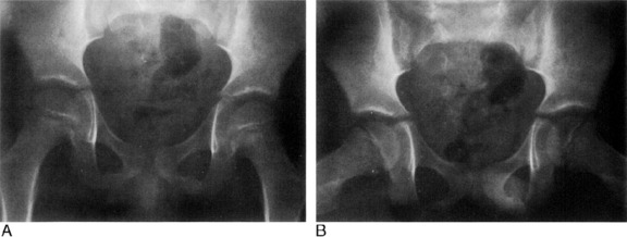
Cheerleader’s “splits” can create a similar avulsion of the ischial tuberosity apophysis on one or both sides (Fig. 16-43). The time of appearance and fusion of these ossification centers parallels that of the iliac crest.
Until the tenth to eleventh year of life, a radiolucent cartilage separates the ischium and pubis along the inferior ramus (Fig. 16-44). This area of normal development is frequently misjudged as a fracture. During the process of union, this region appears more dense and expanded so as to give the impression of callus formation or tumor. The bilateral appearances are often asymmetric.
The triradiate cartilage forms a Y-shaped configuration at the acetabulum and constitutes the junctures of the pubis, ischium, and ilium (see Fig. 16-44). This becomes completely filled in with bone at about the time of puberty. There have been many occasions when this, too, has been called a pelvic fracture.
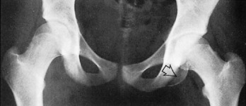
The posterior margin of the acetabulum, somewhat obscured by the femoral head and requiring an oblique view to see adequately, may arise from a separate ossification center and easily simulate a fracture because of its linear appearance. This variation is often a bilateral finding. A variable-sized ununited center, the os acetabuli, may persist throughout life. It is located along the superolateral margin of the acetabulum (Fig. 16-45).
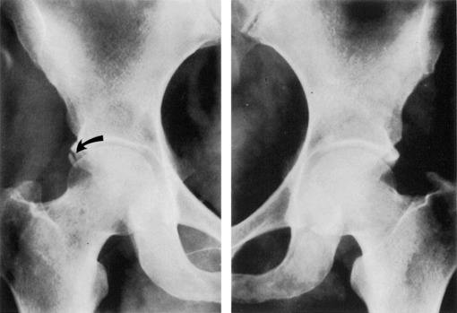
Fig. 16-45 Os acetabuli. The right side demonstrates this normal variant (arrow). None is seen on the left.
In addition to the bones themselves, there are certain soft tissue densities about the hips and pelvis that demand attention. The shadows of the obturator internus, the iliopsoas, and gluteus medius muscles are ordinarily outlined by radiolucent adipose tissue. Because of their close approximation to the joint capsule, blood or pus that distends the joint is reflected on the roentgenogram by displacement of these fat stripes.
TRAUMA
A rather significant degree of correlation exists between the presence of an extracapsular subtrochanteric hip fracture and a pathologic process. In other words, do not take for granted that such a fracture is related purely to trauma, because this is a favorable site for metastasis. Hip dislocations are discussed in Chapter 10. From a radiologist’s point of view, it is useful to comment on some of the roentgenographic changes seen in this type of injury. First of all, hip dislocations are classified as anterior, posterior, and central. In the most common posterior form of dislocation, the injury may not always be readily apparent on the anteroposterior film. There may be a slight difference in the size of the femoral heads as a result of slight rotation of the displaced hip. Shenton’s line may be askew. This is a continuous, smooth line formed along the sweep of the inner margin of the femoral neck, and it normally follows the inferior boundary of the arched contour of the superior ischiopubic ramus. Any disruption of this line would indicate a dislocation. The posterior lip of the acetabulum may be fractured, but as previously noted, a persistent unfused apophysis is sometimes located here.
As seen in Figure 16-46, a central acetabular fracture may be transverse or oblique. The transverse type extends from the anterior acetabular margin backward through the ischial spine, whereas the oblique form is directed more superiorly to the greater sacrosciatic notch. Both actually divide the innominate bone into superior and inferior segments.
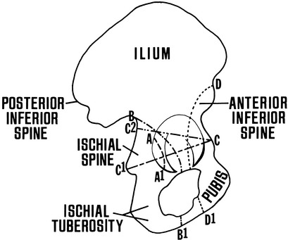
Two other categories of acetabular fractures are depicted in the schematic drawing of Figure 16-46: anterior (iliopubic) and posterior (ilioischial) column fractures. Oblique films, or better, CT, are required for their proper interpretation.
A variety of fractures and/or dislocations result in unstable conditions of the pelvis. Among the more common types that might be encountered is the straddle fracture (Fig. 16-47, A). This situation exists when there are vertical fractures involving the superior and inferior ischiopubic rami on both sides. Less frequently, the fractures are unilateral but with separation of the symphysis pubis. Approximately 30% of such injuries are associated with urethral or bladder trauma.
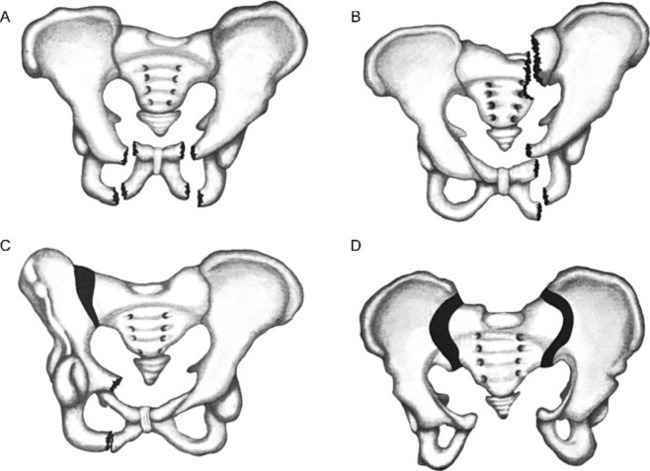
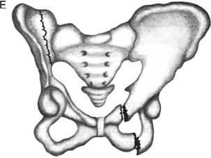
More serious forms of unstable fractures are classified as double vertical fracture-dislocations (see Fig. 16-47). There are three such types, and all have in common a double component involving the pelvic ring, anterior and posterior to the acetabulum.
When there are unilateral vertical fractures of the ischiopubic rami or a dislocation of the symphysis pubis in combination with a fracture about the ipsilateral sacroiliac joint or a dislocation of that joint, the condition is termed Malgaigne’s fracture (Fig. 16-47, B and C). The hemipelvis on the involved side may become displaced up or down and create a true unstable situation.
A “sprung pelvis” is another form of an unstable double vertical injury. Here, there is separation of one or both sacroiliac joints and a disjunction of the symphysis pubis (Fig. 16-47, D). Careful inspection of the sacroiliac joints should be made in any patient with displacement of the pubis.
The third type of double vertical pelvic injury is the so-called bucket-handle fracture (Fig. 16-47, E). There are fractures through the upper and lower rami of the anterior pelvic ring. The opposite or contralateral sacroiliac joint is separated or demonstrates a juxtaarticular fracture.
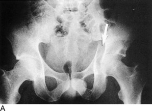
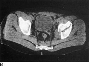
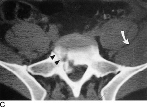
CT has revolutionized the radiologist’s ability to evaluate fractures of the pelvis. The transverse images provide greater anatomic detail, which allows one to distinguish important relationships and significant fragment displacements not readily apparent on the standard x-ray films. Furthermore, alterations in the soft tissues can be better determined, such as the development of associated hematoma formation. Totally unsuspected fractures that are not apparent on routine films often are visualized by CT. Furthermore, the sacroiliac joints are much better depicted (Fig. 16-48).
TUMOR
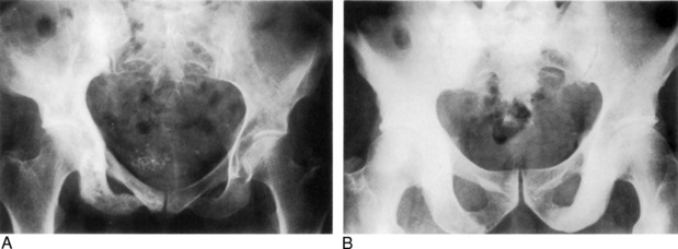
Not infrequently, a pelvic roentgenogram is seen that shows a marked increase in density. The majority of these cases represent either diffuse osteoblastic metastasis or Paget’s disease. The differentiation, as already observed, can often be made using basic characteristics of each (Fig. 16-49). Notably, Paget’s disease discloses increased volume of bone and a greatly thickened trabecular pattern. Moreover, it may be confined to one side of the pelvis, a less likely occurrence in metastasis. In a small percentage of individuals (fewer than 1%), Paget’s disease may transform to osteogenic sarcoma.
SACROILIAC JOINTS
On the other hand, ankylosing spondylitis (Marie–Strümpell disease) is often bilaterally symmetric (see Chapter 8). The roentgenographic changes are distinctly different from those of rheumatoid arthritis. However, the sacroiliac joint alterations of rheumatoid arthritis and the other noninfectious inflammatory lesions can be very similar and preclude a differentiation in some cases. The fundamental findings of ankylosing spondylitis involve the ilium initially and consist of irregular deossification, articular erosions, indistinct subchondral line density, and spotty sclerosis. Subsequent reactive new bone formation often bridges the joint space and can eventuate in actual ossification and obliteration of the joints. Another distinguishing peculiarity of rheumatoid spondylitis as it pertains to the pelvis is a fine to coarse spiculated or “whiskering” appearance that may develop along the inferior margins of the ischial tuberosities.
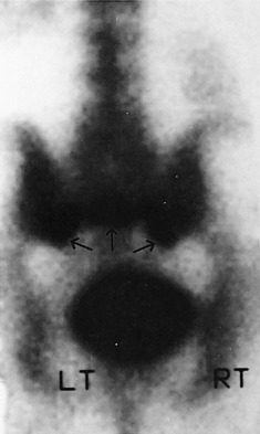
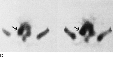
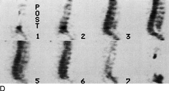
An uncommonly recognized source of back pain in elderly individuals suffering from osteoporosis is the stress or insufficiency fracture of the sacroiliac joints. This entity can be readily diagnosed on radionuclide bone scans with a characteristic H-shaped uptake of the isotope (Fig. 16-50).
THE KNEE
ROENTGENOGRAPHIC EXAMINATION
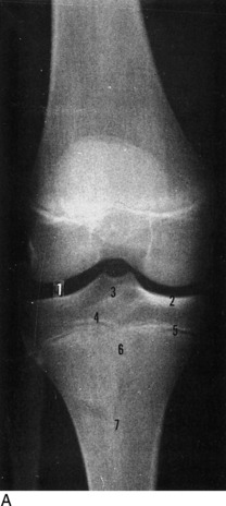
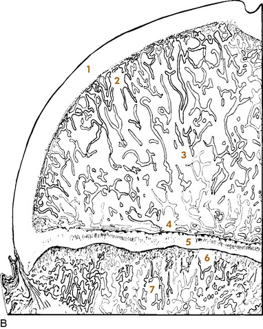
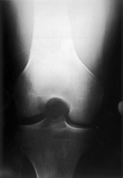
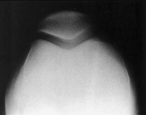
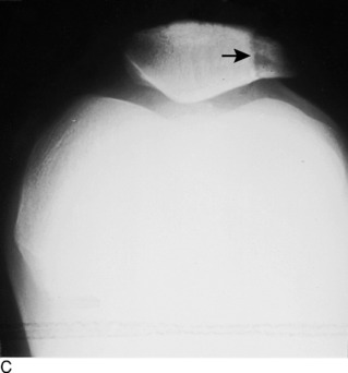
The basic minimum examination of the knee consists of supine anteroposterior and flexed lateral views. The latter film should be obtained with the knee bent at least 45 degrees with the affected knee flat on the table and the patient on his or her side, although this may be impossible in an acutely injured, fluid-filled joint or in a severely osteoarthritic knee. Certain situations call for other views. Internal and external oblique films may help visualize otherwise nonvisible subtle fractures of the tibial plateaus or femoral condyles. These features, as well as the intercondylar space and the tibial spine (intercondylar crest), can also be evaluated with a tunnel film (Fig. 16-51). The tangential, or “sunrise,” projection affords another perspective of the patella and the femoropatellar joint (Fig. 16-52). A fat-blood level may be detected on an across-the-table horizontal beam roentgenogram and indicate an intraarticular fracture in which marrow fat and blood have been extruded into the joint.
ROENTGENOGRAPHIC ANATOMY AND DEVELOPMENTAL VARIATIONS
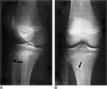
The proximal tibial epiphysis becomes visible by ossification in the last 2 months of fetal life. Like the femoral epiphysis, it fuses to the shaft by the twentieth year. Between the ages of 7 and 15 years, the tongue-shaped anterior and inferior extension of the epiphysis is visible and forms the anterior tibial tuberosity or spine (Fig. 16-53, A). The tuberosity is an extremely variable structure that develops in an irregular fashion and often has a fragmented appearance. This should not be confused with a fracture or Osgood–Schlatter disease.Its features on the anteroposterior view can be particularly bewildering (Fig. 16-53, B). On the frontal view, a radiolucent cleft often appears over the proximal tibial shaft.
Ossification of the patella is irregular in nature and arises from multiple foci. In the young, it may be divided into several segments. It often has a granular appearance with irregular borders. Before complete fusion of the patellar ossification centers, there can be confusion with fractures, or its irregular outline may suggest osteochondritis (Fig. 16-54).
One of the more difficult problems associated with roentgenographic appraisal of the patella is the commonly observed anomaly of patella partita. This condition is usually bilateral but must be differentiated from fractures. A bipartite status is the most prevalent form, but multipartite patellae also exist, and as many as six different segments have been reported. In the usual instance, or bipartite state, a radiolucent line separates a smaller segment that almost always occupies the upper-outer quadrant, although many other rare variations are found (Fig. 16-55). There have been cases described for patellar partition into anterior and posterior portions.
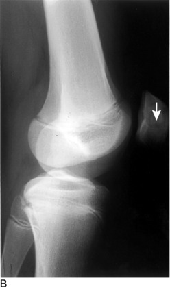
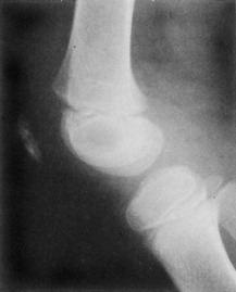
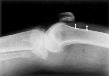
A somewhat distracting osseous shadow, the fabella, is seen in 10% to 20% of knees along the posterior aspect (Fig. 16-56). A small sesamoid bone of varying size and shape, it lies within the lateral head of the gastrocnemius muscle and is best seen on the lateral view. Many times, it overlies the border of the lateral femoral condyle and appears as an avulsion fragment on the anteroposterior film. The bone is most often a bilateral finding and is seen more often in males. It must be differentiated from a fracture, loose joint body, foreign body, and phlebolith.

It is not too surprising to visualize a radiolucent slit within the knee joint and, usually more frequently, within the hip and shoulder joints of children. This phenomenon is linked to a vacuum effect and is caused by pulling on the extremity or by producing forced adduction or abduction. It is important that this not be interpreted as abnormal. Nevertheless, in the elderly population, it is a pathologic observation and may be seen in severe arthritis with degeneration of the cartilage. The finding is a potential perception in a vertebral spine with advanced degenerative disc disease.
TRAUMA
The majority of roentgenograms done because of trauma to the knee will be normal. At times, a joint effusion will be demonstrated with soft tissue fullness of the suprapatellar bursa, but visualized fractures are uncommon. With fractures extending into the joint, a fluid–fluid level can be demonstrated on cross-table lateral views resulting from blood layering with marrow fat (lipohemarthrosis; Fig. 16-57). Fractures can involve one or both femoral condyles, the tibial tuberosity, or the proximal third of the fibula as well as the patella. As many views as necessary should be utilized to evaluate these injuries. Stress fractures about the knee, especially the proximal tibia, are not uncommon and occasionally show a dense line of compacted trabeculae but may require a radionuclide bone scan or MRI to document.
TUMOR
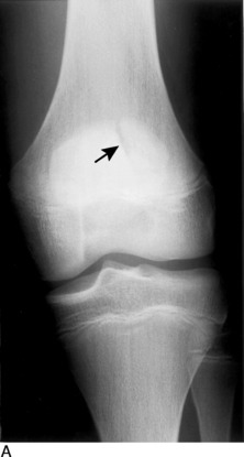
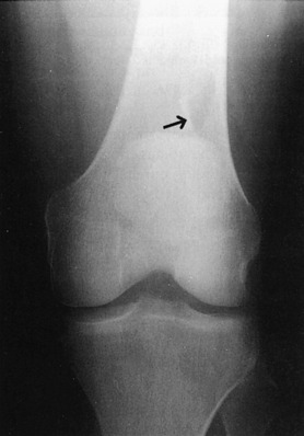
Of the many benign tumors involving the knee region, osteochondroma is probably one of the more frequent, with the exception of benign cortical defects (Fig. 16-58). The latter are peripherally located, round to oval radiolucencies that often measure no more than 2 cm. They have a sharply defined sclerotic margin and are common in the metaphyseal areas of the distal portion of the femur and the proximal and distal thirds of the tibia. They are asymptomatic and discovered incidentally on roentgenograms performed for other reasons. With advancing age, they tend to disappear. The osteochondroma is seen as a bony protuberance of variable size, contiguous with the femoral or tibial metaphyseal or diaphyseal bone marrow and extending away from the joint in the direction of the tendons and muscles (Fig. 16-59). Osteochondromas have an invisible cap of cartilage. Solitary osteochondromas are less frequently demonstrated about other joints of the body. When these exotoses are multiple, they constitute a hereditary bone dysplasia designated as diaphyseal aclasis.
Although not ordinarily considered under the topic of tumors, bone infarcts, frequently located in the distal third of the femur, can create confusing roentgenographic changes. They occur in caisson disease, pancreatitis, and various vascular disorders. Any segment of bone, epiphysis, metaphysis, or diaphysis can be involved, but the alterations are confined to the medullary cavity. They appear as irregular sclerotic longitudinal streaks, occasionally with fine cystic patterns resembling a corkscrew (Fig. 16-60).
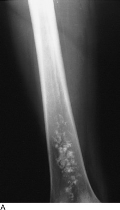
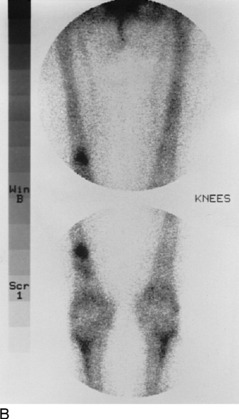
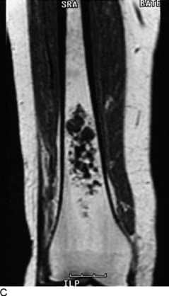
Fig. 16-60 Bone infarct of the distal third of the femur. A, X-ray. B, Radionuclide bone scan. C, Coronal T-1 weighted spin-echo magnetic resonance image.
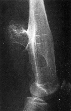
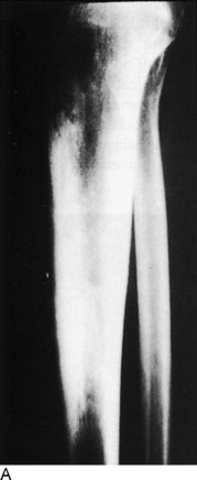
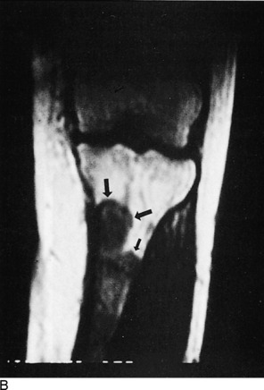
The knee has the dubious distinction of being the most common site for the development of osteosarcoma. The metaphysis of the distal portion of the femur accounts for approximately 75% of all osteogenic sarcomas. This primary bone malignancy tends to occur during puberty, with boys being more commonly affected than girls. The roentgenographic changes take many forms, either being purely osteolytic or showing a mixed destructive and osteosclerotic pattern (Fig. 16-61). Extensive soft tissue involvement is the rule. Periosteal reaction can be exuberant, eventually forming the typical spiculated “sunburst” appearance, although this is not always present (Fig. 16-62).
Under the heading of round-cell tumors, Ewing’s sarcoma is manifested as a solitary lesion arising in the diaphysis and metaphysis of long bones, particularly the femur; however, it has been observed with relative frequency in the humerus and ulna as well as the pelvis. Originating in the bone marrow, it produces a characteristic layered periosteal thickening resembling an “onion skin.” A variable patchy dissolution without significant expansion is imparted to the osseous architecture. Unfortunately, the symptoms of fever and pain and the sarcoma’s roentgenographic manifestations can resemble those of osteomyelitis in the child and adolescent, and indeed the distinction may be extremely difficult to make.
ARTHRITIS
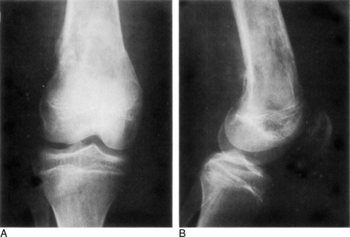
Osteoarthritis is a familiar affliction of the knee (Fig. 16-63). Degenerative wear and tear produce the changes with progressing age, but secondary posttraumatic arthrosis is also a leading offender. Minimal joint space narrowing is one of the earliest roentgenographic changes reflecting wearing and thinning of the articular cartilage. Standing weight-bearing films might be required to demonstrate this finding. The decreased height of the joint space may be accompanied by increasing sclerosis of the subarticular region of the tibia, quite often the medial condyle. The femoropatellar joint undergoes similar alterations of narrowing and associated sclerosis of the articular surface of the patella. Eventually, the process leads to bony spurs arising from the articular margins of the femur, tibia, and patella. These osteophytes may become significantly large so that function is impaired.

OSTEOCHONDRITIS
There are several disease entities classified as osteochondritis or aseptic necrosis involving the knee. The abnormalities of osteochondritis dissecans have already been described. Osgood–Schlatter disease is another form involving the anterior tibial tubercle. As mentioned previously, there is a significant variation in the roentgenographic appearance of the normal tuberosity, and the diagnosis is primarily a clinical one. Even though there may be sclerosis and/or fragmentation, this does not necessarily constitute Osgood–Schlatter disease. The only roentgenographic abnormality, almost universally present in the acute phase, is overlying soft tissue swelling. The principal purpose for obtaining the films is to exclude some other lesion, such as tumor or infection.
THE ANKLE AND FOOT
ROENTGENOGRAPHIC EXAMINATION
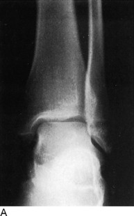
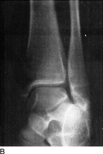
Three views are mandatory for proper evaluation of the ankle, and three projections are necessary for the foot examination. As elsewhere in the skeleton, modified and special films can clarify suspicious areas. For the ankle, the three films include anteroposterior, lateral, and oblique projections. The oblique study, or mortise view, is obtained by rotating the foot internally 10 to 15 degrees (Fig. 16-64). Even though the calcaneus, tarsal bones, and bases of the metatarsal bones are not considered anatomically a part of the ankle, they should be included, because associated or isolated injuries to these structures may be found when symptoms point only to the ankle. A good example of this is a fracture of the base of the fifth metatarsal bone.
In the presence of soft tissue swelling after trauma but without an associated fracture, ligamentous damage must be considered. Stress anteroposterior filming using manual abduction and adduction of the heel may be indicated. Widening of the ankle mortise strongly suggests a tear in either or both the medial deltoid ligament or lateral collateral ligaments. Because of pain, maneuvering the ankle for stress views may require local anesthesia. However, the orthopedic surgeon may wish an MRI study of the ankle for defining the complex array of ligaments, tendons, and muscles, as well as assessing for traumatic bone bruises, fractures and abnormal fluid collections (edema and hematomas).
ROENTGENOGRAPHIC ANATOMY, VARIANTS, AND PATHOLOGY
Ankle
As mentioned previously regarding other growth centers, a linear sclerotic zone of bone condensation or a lucent line of incomplete union may persist in the distal portion of the tibia where the epiphyseal line existed. Additionally, just as in the distal thirds of the radius or femur, a variable number of regular transverse bands of increased bone density may be observed in the tibial metaphysis. These so-called growth lines are normal; they tend to disappear with age and should not be confused with a pathologic process such as the lines of lead poisoning.
One of the best-known accessory skeletal elements of the ankle in addition to the os subtibiale and os subfibiale is the os trigonum (Fig. 16-65). Situated behind the talus near the posterior aspect of the talocalcaneal joint, it is best viewed on the lateral roentgenogram. Its shape and size are variable, and it may measure 1 cm or more. Despite its frequency, it still is commonly misinterpreted as a fracture.
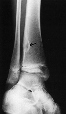
Benign cortical defects are a relatively frequent finding in the distal portion of the tibia in children and are just as common in the femur and tibia about the knee. Their characteristics have been described in the section of the knee. They are easily distinguishable on roentgenograms from more serious lesions (Fig. 16-66).
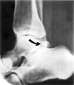
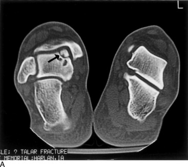
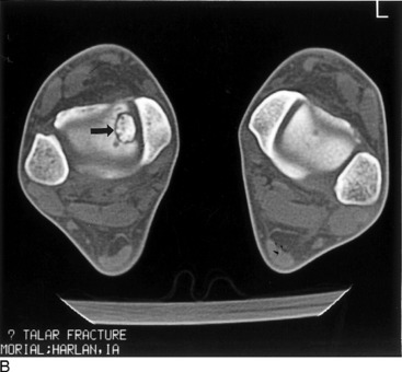
Osteochondritis dissecans, discussed elsewhere, is most commonly found involving the knee. This form of avascular necrosis, which is thought to be related to trauma, occurs in other areas as well, including the elbow and ankle. An osteochondral fragment of varying size, but usually small (less than 5 mm), can retain its postion in relation to the articular margin or become displaced into the joint as a loose body. Rarely, the abnormality may not be identified on standard radiographs. CT or MRI may be required to detect the defect in the clinical setting of persistent pain and disability and a normal radiographic study (Fig. 16-67).
Foot
The calcaneus anatomically consists of a body and a large posterior tuberosity. The sustentaculum tali forms a platform of bone along the inner superior surface of the body that provides support to the anterior portion of the talus. The posterior facet, behind the sustentaculum tali, is that portion of the talocalcaneal (subtalar) joint that slopes downward, as seen on the lateral reoentgenogram, and into which the lateral triangular process of the talus projects (Fig. 16-68).
To properly evaluate the heel, especially in cases of trauma, in addition to the lateral film a tangential (axial) projection and both oblique views are required. To obtain the axial exposure, the patient is seated on the table with the heel against the film. A towel or long piece of gauze is placed around the ball and toes of the foot, and the individual is instructed to flex the foot by pulling on the cloth. The tube is angled 40 degrees toward the head and centered over the heel. Multiple axial films from angles of 20 to 40 degrees may be necessary to properly demonstrate the location and extent of a fracture. Here again, however, CT assessment reveals much more detail and not only diagnoses a fractured calcaneus (or other tarsal bone) but reveals the degree of separation and displacement to determine the appropriate surgical approach for fixation.
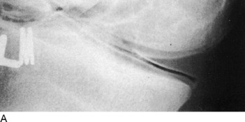
When viewing the os calcis on the lateral examination, it is mandatory that Boehler’s angle be measured. This is formed by the intersection of (1) a line drawn from the dome of the os calcis at the talocalcaneal joint to the anterior process of this same bone, and (2) a line extending from the posterior tubercle to the dome of the calcaneus (Fig. 16-69). Normally, this measures between 20 and 40 degrees. With compression fractures, this angle is reduced. Subtle compression fractures may be overlooked without measuring this angle.
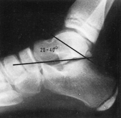
Fig. 16-69 This lateral film of an ankle demonstrates Boehler’s angle. Normal measurement is 20 to 40 degrees.
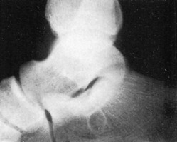
A somewhat rounded to triangular area of lucency that is relatively well circumscribed is occasionally observed in the body of the calcaneus on the lateral roentgenogram (Fig. 16-70). This finding can create interpretive difficulties, because it simulates a cyst. This has been proved anatomically to represent a normal area of thinned, deficient trabeculae. This is usually an incidental finding and can be very worrisome when seen. True cysts, however, rarely occur.
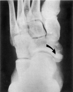
When considering the tarsal navicular bone roentgenographically, there are several lesions that deserve discussion because of their relatively common occurrence. Traumatic injuries to the tarsal navicular are uncommon. Avulsion fractures along the dorsal surface may be found near the talonavicular joint and require differentiation from an os supranaviculare. The medial tuberosity that serves for the insertion of the posterior tibial tendon may be subjected to forces resulting in fracture. Importantly, such a fracture may be associated with a fracture of the cuboid bone, often with dorsal subluxation of the navicular. An accessory bone, the os tibiale externum, located behind the tuberosity, is more frequent than tuberosity fractures and may be confused with one (Fig. 16-71).
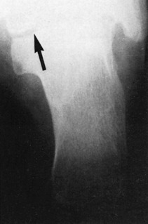
Several interpretive challenges are presented by the appearance of the base of the fifth metatarsal bone. The longitudinally oriented shell-like apophysis can be roentgenographically dissimilar in the feet of the same individual and vary in size and shape. Furthermore, it may persist unfused throughout life, but this is an uncommon event. Ordinarily, the distinction between the apophysis and a fracture is relatively simple, because the growth line is oriented to the axis of the shaft, whereas a fracture is transverse in almost all instances (Fig. 16-72). An accessory bone, the os vesalianum, alluded to previously, is located near the junction of the proximal metatarsal tuberosity and the cuboid. This fact should be remembered when evaluating trauma to this area.

A moderate degree of overlap of the bases of the metatarsal bones is noted to a greater or lesser degree on all views, but more so on anteroposterior projections. With the Mach effect in mind, this can lead and has led to the diagnosis of many erroneous fractures. The internal oblique film tends to reduce this problem to some extent.
One traumatic lesion involving the metatarsal area merits special attention but, fortunately, is infrequent. Lisfranc’s fracture-dislocation involves the tarsometatarsal junction and consists essentially of dorsal displacement of the metatarsal bases. Two basic forms exist: homolateral and divergent. In the homolateral type, the lateral four metatarsals are dislocated posteriorly and laterally, often with associated fractures at the bases (see Chapter 13). The divergent type exists when the first metatarsal is displaced medially and the others are dislocated laterally. The disfigurations may be subtle, and the normal straight alignment of the second metatarsal and middle cuneiform bones should be used (Fig. 16-73).
Osteochondritis dissecans, discussed elsewhere, is most commonly found involving the knee. This form of avascular necrosis, which is thought to be related to trauma, occurs in other areas as well, including the elbow and ankle. An osteochondral fragment of varying size, but usually small (less than 5 mm), can retain its position in relation to the articular margin or become displaced into the joint as a loose body. Rarely, the abnormality may not be identified on standard radiographs. CT or MRI may be required to detect the defect in the clinical setting of persistent pain and disability and a normal roentgenographic study (see Fig. 16-73).
Specialized Radiologic Studies of the Musculoskeletal System
NUCLEAR MEDICINE PROCEDURES
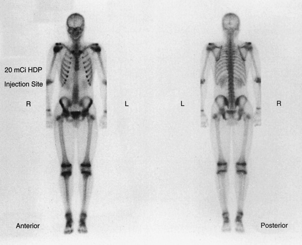
In a few of the previous sections, the use of radioactive isotopes in the evaluation of certain bone disorders has been mentioned. For some time now, it has been known that phosphorus compounds are metabolized in bone at a rapid rate, and this assimilation can be readily detected by a scintillation camera when the substance is tagged by the radiotracer 99mTc (Fig. 16-74). Areas of very rapid bone turnover (such as those seen in healing fractures, aggressive tumors, and infections) can readily be detected by bone scanning.
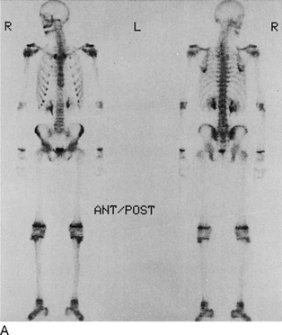
There are occasions when fractures are extremely subtle or undetectable on standard roentgenograms, such as fractures that may be seen in the hip. Two to 5 days are required after the injury before scans demonstrate the fracture optimally. Abnormal increased activity may persist for up to 2 years or longer, depending on the severity of the injury. Nuclear scans can be particularly helpful in determining the age of compression deformities of the vertebral bodies. In recent years, SPECT imaging has provided an even more sensitive nuclear method for detecting bone abnormalities. The technology is not unlike computerized roentgenographic tomography in that multiple detector heads, up to three, rotate about the patient. The digital information derived from the amount of isotope activity from bone can be reconstructed by a computer into tomographic slices in all planes (sagittal, coronal, and axial). In effect, thin slices of anatomic and physiologic data can be displayed (Fig. 16-75).
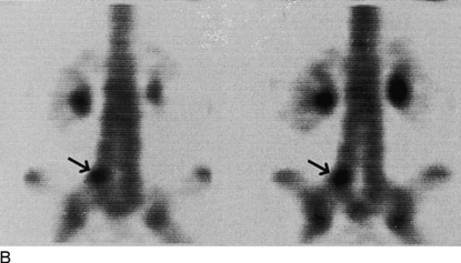
The value of the radionuclide three-phase bone scan in differentiating osteomyelitis from cellulitis is depicted in Fig. 16-76. A limited three-phase study over the area of interest can distinguish between the two processes in the majority of cases. This examination consists of an initial dynamic, or vascular, phase performed at the time of isotope injection followed by an immediate second phase, or soft tissue uptake stage. Standard 2-hour delay images are then obtained for bone uptake. If the results are inconclusive, an indium-111 leukocyte study can be performed, in which the patient’s own white blood cells are tagged and reinjected. This often helps identify bone versus soft tissue inflammatory infectious disease.
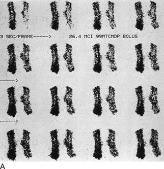
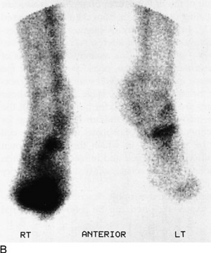
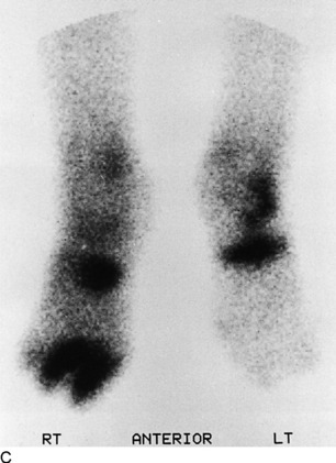
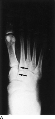
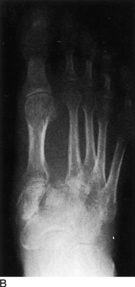
Fig. 16-76 Three-phase bone scan demonstrating osteomyelitis of the second and third toes of the right foot in the absence of roentgenographic findings. A, Dynamic, or angiographic, phase shows definite focal hyperemia to the sites of infection. B, The second, blood-pool, phase depicts persistent focal uptake. C, The final delayed images document localized isotope activity in the region of bone infection.
DIAGNOSTIC ULTRASOUND
Exquisite image resolution and anatomic detail are possible with state-of-the-art, real-time diagnostic ultrasound systems. High-precision, small-parts transducers in the range of 7.5 to 10 mHz are now available. These afford excellent structural delineation of the thyroid gland, testicles, and breast lesions, as well as vascular studies combined with Doppler flow measurements. Both venous and arterial vascular assessment can be performed by Doppler ultrasound methods to evaluate for deep venous thrombosis and arterial occlusive disease of both upper and lower extremeties. Bone cannot be imaged with ultrasound; that, along with its inability to be transmitted through air, is a distinct disadvantage. However, soft tissues provide an excellent medium for evaluation by sonography. The muscles of the extremities in particular can be examined easily and without discomfort to the patient. Soft tissue tumors, although uncommon, if unresectable can be followed by sequential sonographic studies, with their response to therapy recorded. Invasive characteristics such as osseous, neural, or vascular involvement cannot be depicted with ultrasound as well as with CT or MRI, however. Biopsies of such masses are easily performed under the guidance of ultrasound.
ARTHROGRAPHY
From a historical perspective, standard radiographic arthography is discussed despite the decline in its use.
Arthrographic procedures carry a low morbidity, are easily tolerated as an outpatient examination, and are quite simple to perform. Sterile technique is required in all cases along with local lidocaine (Xylocaine) anesthesia. Shoulder arthrography has its greatest application in the study of rotator cuff tears (Fig. 16-77). It is also useful in the analysis of adhesive capsulitis (frozen shoulder), arthritis, synovitis, and capsular integrity, in addition to being helpful in the detection of loose bodies and abnormalities of the biceps tendon. The cartilaginous rim of the glenohumeral joint, the glenoid labrum, can be depicted and examined for tears and degeneration similar to examination of the knee menisci (Fig. 16-78).
XEROGRAPHY
Although no longer available, for historical purposes, xerography is briefly discussed.
Xerography provided information regarding the soft tissues that was not available on roentgenographic film images (Fig. 16-79). It was particularly helpful in detecting relatively nonopaque foreign bodies such as glass and wood. Xerography has been supplanted by CT and MRI in the appraisal of musculoskeletal abnormalities.
ANGIOGRAPHY
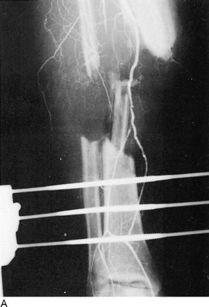
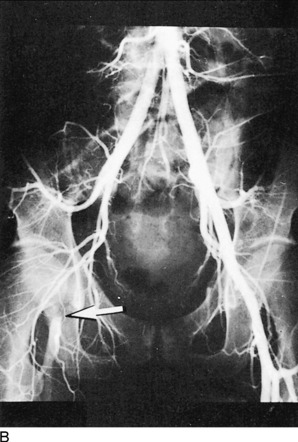
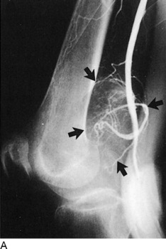
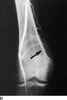
Angiography has a somewhat limited role in orthopedics. Its principal contribution is in the area of trauma, when fractures of the extremities are infrequently complicated by vascular injury (Fig. 16-80). Less often, the evaluation of primary osseous or soft tissue neoplasms can be aided by using angiograms (Fig. 16-81). Preoperative assessment of the degree of vascularity of the lesion in addition to its major blood supply can be invaluable to the surgeon’s approach.
COMPUTED TOMOGRAPHY
Distinguishing between benign and malignant soft tissue tumors in certain cases can be accomplished by CT. Benign lesions can be sharply demarcated and uniformly homogeneous and are confined to a single muscle or compartment. They may compress or displace vessels and nerves but, of course, do not invade them, which can be identified by CT. Conversely, malignant soft tissue masses have no well-defined margins because of their infiltrative nature and naturally invade and distort adjacent nerves and vessels. Extension into adjoining bone is also well demonstrated by CT. Furthermore, malignant tumors often involve multiple muscle groups and compartments.
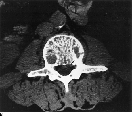
With the advent of spiral technology to CT, 3-D computer reconstruction of bony anatomy is available and provides yet another advancement in imaging capabilities (Fig. 16-82). CT can be very useful in selected trauma cases, particularly those involving complex anatomic areas such as the spine, pelvis, hips, and shoulders and knees (Fig. 16-83). The cross-sectional image display of CT eliminates the overlapping structures and depicts the spatial relationship of fracture fragments to joints, muscles, nerves, and vessels. In addition, it can detect and define the extent of associated hemorrhage and hematoma formation. Modern multidetector spiral CT machines have become so powerful and fast that distal extremety angiograms with intravenous contrast are now possible and may eventually eliminate the need for more invasive intraarterial catheter methods.
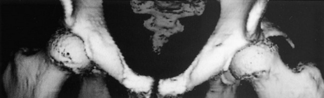
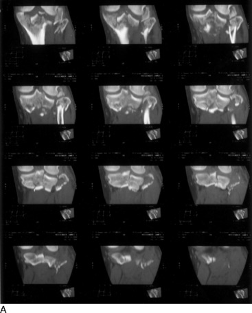
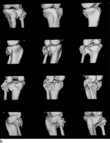
On occasion, infectious processes involving bone, joints, and soft tissues can be best demonstrated by CT. However, osteomyelitis of long bones and infections of the spine and intervertebral discs usually do not require CT, except when the diagnosis is in doubt with the more conventional means. Soft tissue abscesses may at times be difficult to distinguish between tumor or hematoma. Early in the process, an abscess may have the same density as surrounding muscles, but it eventually undergoes central necrosis with liquefaction and acquires a low-density center with an irregular peripheral high-density wall. The presence of air within an abscess suggests communication with the skin surface or air-forming bacteria.
MAGNETIC RESONANCE IMAGING
Clinical indications for MRI are well established. Applications of this diagnostic modality, particularly in the central nervous system, are well known and increasingly used. However, the development and usefulness of MRI in musculoskeletal disorders has become, to say the least, overwhelming. Recent developments in computer software and techniques have led to an increased usage of MRI in evaluation of the spine and extremities, and it has replaced CT in a number of areas. MRI has multiplanar capabilities; that is, it can image in the sagittal, coronal, and the axial (transverse) planes in addition to oblique variations of these, thus providing more useful information than CT does, which is limited to the axial plane. Furthermore, unlike CT, it possesses greater contrast resolution and better delineates muscles, tendons, ligaments, fat, and fluids. Because it does not use ionizing radiation, MRI has no harmful effects and, indeed, is thought to be risk free for most patients. MRI contraindications include pregnancy (unknown teratogenic effects), patients with pacemakers and electrostimulating devices, and individuals with intracranial ferromagnetic metal clips and metallic foreign bodies in close proximity to vital structures, which can be displaced by the strong magnetic force. Futhermore, metals can cause annoying artifacts that can obscure imaging detail. Most prosthetic devices and surgical clips today are nonferromagnetic and do not cause any significant problems to the patient or degrade the images.
MRI OF THE SPINE
The vertebral bodies and their posterior neural arch components, as well as the surrounding muscles, can be well demonstrated with MRI. Additionally, the intervertebral discs are optimally visualized. MRI also depicts the contents of the central neural canal, including the cord, nerve roots, dura, and ligamentum flavum. The neural foramina and associated exiting nerve roots can be identified on sagittal and axial views. Figure 16-84 illustrates the normal midline sagittal appearance of the cervical, thoracic, and lumbosacral spine. Standard MRI protocol consists of 3- to 5-mm contiguous sagittal images from the neural foramina from one side to the other (Fig. 16-85). Selected axial images through the intervertebral disc spaces are also performed (Fig. 16-86). Occasionally, coronal views are obtained that simulate roentgenographic contrast myelography.
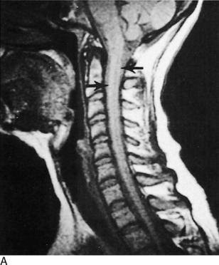
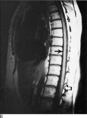
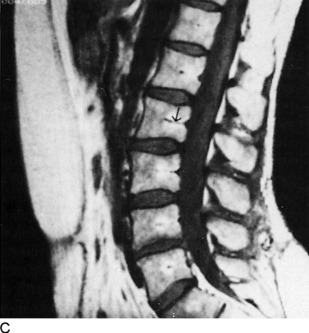
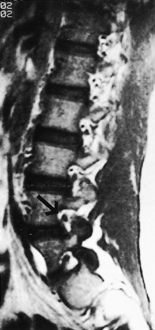
Fig. 16-85 Off-midline sagittal MRI of the lumbar spine demonstrates the neural foramina and their exiting nerve roots (arrow).
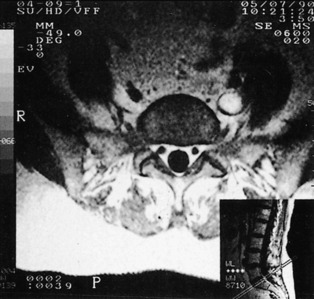
Congenital Malformations
MRI of congenital malformations of the spine in some instances may be the only means of delineating the abnormality. Sagittal cervical spine images clearly depict the Arnold–Chiari malformation with herniation of the cerebellar tonsils through the foramen magnum. There may be an associated syringomyelia dissecting the cord, and this can be extremely well seen on MRI studies (Fig. 16-87). MRI provides a noninvasive way to evaluate menin-goceles and meningomyeloceles. With these entities, a tethered cord and associated lipoma are well appreciated below the conus medularis.
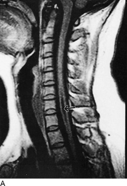
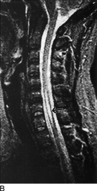
Disc Disease
The clinical diagnosis of a herniated intervertebral nucleus pulposus can be very dramatic but on occasion can be very subtle. After following a conservative clinical approach for a period of time without improvement of symptoms, the clinician may elect to evaluate the patient by some type of imaging procedure to diagnose and document the presence or absence of a herniated disc. Graphic visualization of a herniated disc can be an imaging challenge by any method. In the cervical region, bulging, protruding, and herniated discs lend themselves readily to MRI evaluation (Fig. 16-88), although the distinction between bulging and herniation may at times be impossible. Lumbar spine disc herniation is best visualized by MRI, essentially replacing CT (Fig. 16-89). But the choice of procedure depends on availability, economic considerations, and to some extent, patient selection. An equivocal CT study may require MRI to best delineate the lesion, but less often the opposite is true.
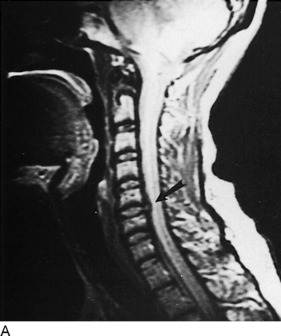
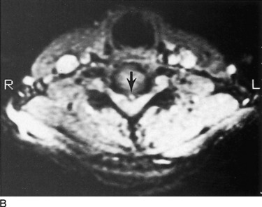
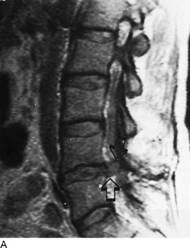
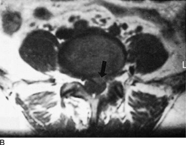
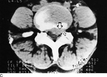
One area of difficult clinical management is the postoperative spine. Contrast myelography or CT seldom can distinguish between postsurgical scar tissue and a recurrent herniated disc. With the introduction of an intravenously administered “contrast” agent, MRI is capable of making the distinction between the two. Gadolinium is a stable paramagnetic metal ion that is combined with diethylenetriamine pentaacetic acid (DTPA). When injected, the substance can enhance tissues with adequate vascularity by changing their magnetic field. Disc material, being essentially nonvascular, will not enhance, whereas scar tissue, which possesses a vascular supply, will (Fig. 16-90).
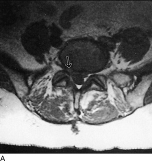
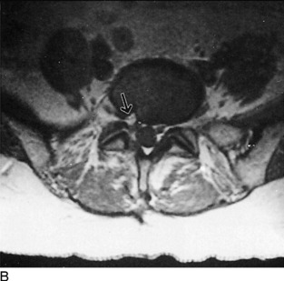
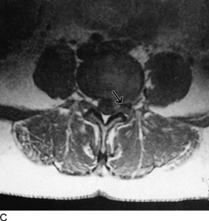
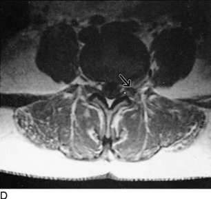
Spondylitis
Early degeneration of the intervertebral disc material can be identified by MRI even before changes occur on roentgenographic films and CT; these changes include disc space narrowing and spur formation. A change in signal intensity (brightness) of the disc on the MRI sagittal images heralds the beginning of the pathologic process, a result of dehydration of the nucleus pulposis (Fig. 16-91). As the disease progresses with disc space compression and production of osteophytes, MRI aids in defining the degree of spinal stenosis that can occur on the central neural canal and the neural foramina in both the axial and sagittal planes. The encroachment of degenerative spurs on the dural sac, their displacement of nerve roots, and their effect on the cord are all adequately assessed by MRI (Fig. 16-92).
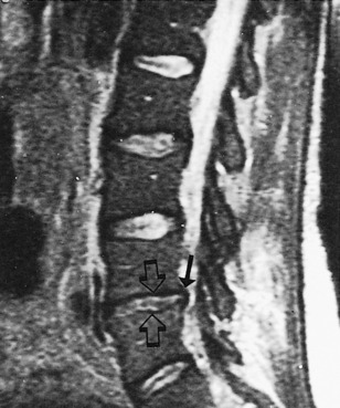
Fig. 16-91 Degenerative disc disease of the lumbar spine at the L4-L5 level. Narrowing of the interspace is evident, and osteophyte formation is noted (open arrows). Also note the decreased signal intensity (darkness), greatest at L4-L5 but involving all discs; this indicates the decreased water content of the degenerating nucleus pulposus. Posterior osteophyte (closed arrow) resulting in some degree of spinal stenosis.

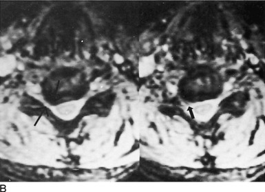
Infection
MRI of infectious processes in and about the spine can be very rewarding. Figure 16-93 demonstrates an unsuspected epidural abscess of the lumbar spine in an individual presenting with a relatively sudden onset of lower extremity neurologic symptoms including back pain, fever, and elevated white blood cell count. A lung infection was thought to be the source for this hematogenously introduced infection.
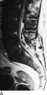
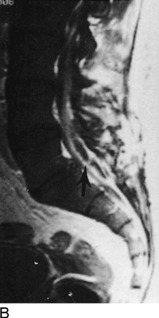
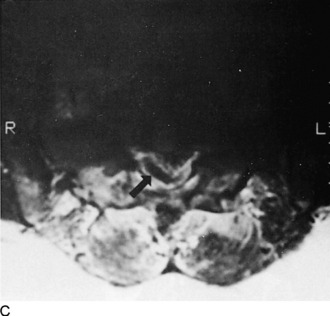
Tumor
Secondary or metastatic neoplasms are the most commonly encountered tumors that involve the spine (Fig. 16-94). These may be hematogenous, such as from lung or breast cancer; lymphatic, such as that from the prostate; or by direct extension from a contiguous lesion. Better definition of the margins of these tumors is afforded by the use of gadolinium, which distinguishes the tumor from surrounding edema and thereby better establishes radiation ports.
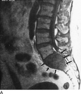
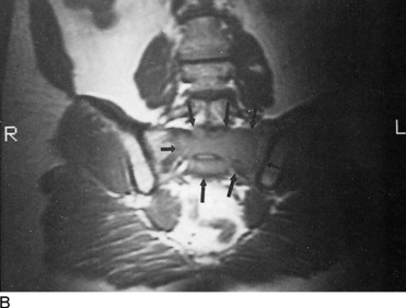
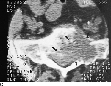
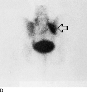
Primary spinal tumors are divided into intradural intramedullary and intradural extramedullary as well as extradural lesions. Intramedullary neoplasms may not be optimally visualized on unenhanced MRI because of extensive infiltration, associated edema, or intratumor necrosis or hemorrhage. Ependymomas and astrocytomas constitute the most common intramedullary tumors. A less common lesion is the hemangioblastoma. All three are best evaluated on MRI after gadolinium injection.
Intradural extramedullary tumors are commonly found to be meningiomas, neurofibromas, or schwannomas (Fig. 16-95). On conventional unenhanced MRI studies, these may be difficult or impossible to identify, especially, if they are less than 5 mm. Larger lesions can displace the dural contents and are more easily detected by these indirect signs.
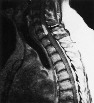
Miscellaneous Spinal Lesions
Demyelinating diseases, of which multiple sclerosis is the most common, are characteristically sensitive to magnetic imaging detection. Histopathologically, the lesions are multifocal destructive myelin zones of as yet unknown etiology that can involve the optic nerves, brain, and spinal cord. They present as areas of increased signal intensity (bright), are of variable size and distribution, range from a few millimeters to several centimeters, and are scattered throughout the white matter. There appears to be a direct relationship between the number and size of these “plaques” and the severity of the symptoms. In addition, as the symptoms wax and wane, so does the appearance of the lesions seen on MRI.
MUSCULOSKELETAL MRI
Diagnostic orthopedic applications of MRI for disorders of the bones, joints, and soft tissues of the extremities are rapidly gaining acceptance. Although MRI will not totally replace the use of CT, nuclear imaging, or even conventional roentgenographic films in evaluation of the musculoskeletal system, there are certain areas and specific abnormalities that are best examined by the magnet. Because of its excellent inherent contrast resolution, MRI can superbly delineate the separate soft tissue components of the extremities (Fig. 16-96). Muscles, tendons, ligaments, fat, cartilage, and fibrous tissue are all excellently displayed. Although the calcium of cortical and trabecular bone possesses no magnetic signal, it can be defined by the adjoining marrow and surrounding muscles and tendons. However, this property of magnetism prevents MRI from defining cortical stress fractures. Tumoral calcifications and ossifications, as well as early cortical destruction and endosteal and periosteal reaction, which are adequately seen on CT, cannot be optimally identified by MRI, which gives it a distinct disadvantage in such situations. Nevertheless, despite these limitations, MRI has become the diagnostic modality of choice for the evaluation of bone and soft tissue trauma such as cartilage, ligament, tendon, or muscular damage.
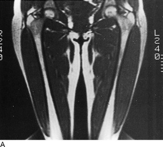
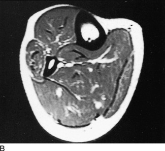
Fig. 16-96 A, Coronal MRI of the femur and thigh. B, Axial image of the tibia and fibula and associated soft tissue detail.
With the development of newer software, the role of MRI has expanded in the area of vascular anatomy. MRI angiography is able to depict brachiocephalic and cerebral vessels and is showing promise in peripheral angiography as well. Without the use of contrast material, arterial and venous structures can be displayed using appropriate phase sequences. As technologic research in this area progresses, it is hoped that MRI angiography may someday replace conventional invasive angiographic procedures.
Tumor
The surgical approach for the treatment of malignant bone and soft tissue tumors today is a conservative one. The objective is limb salvage and restricting resections to a limited degree, thereby providing as much functional capability as possible. The multiplanar display of MRI and its excellent contrast resolution aid greatly in defining the size, location, and extent of a tumor. It can adequately assess marrow involvement, skip lesions, and invasion of adjoining muscles, compartments, blood vessels, and nerves (Fig. 16-97). Of great importance is establishment of the integrity of adjacent joints and articular surfaces.
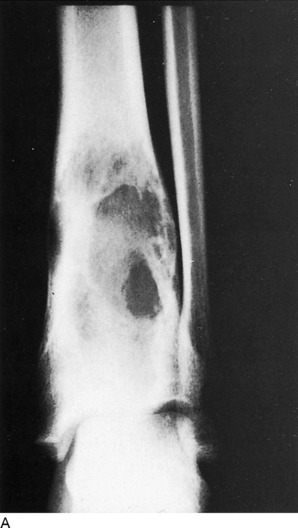
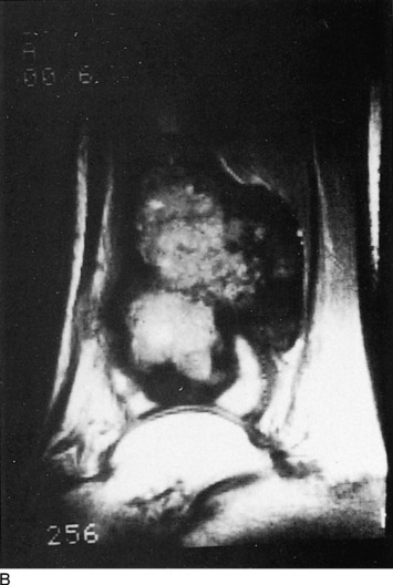
MRI cannot, unfortunately, differentiate between benign or malignant tissue characteristics in the majority of cases. There are a few exceptions; giant cell tumor of bone, for example, will give rise to characteristic fluid–fluid levels within a multi-septated lesion, a unique feature for these neoplasms (Fig. 16-98). Certain types of tissues such as fat or the vessels of a hemangioma have distinctive appearances (Fig. 16-99). Fluid-filled cystic lesions can be separated from solid masses with MRI, and this can aid in appropriate assessment such as needle aspiration or biopsy.
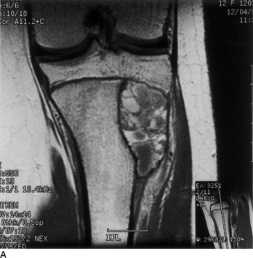
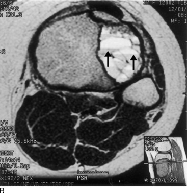
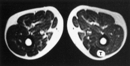
Infection
CT is helpful in determining cortical bone and periosteal findings but is less sensitive to marrow or surrounding soft tissue changes. In cases of infections involving internal metallic fixation devices, the artifacts produced by CT prevent delineation of the abnormalities. The MRI artifacts produced by such devices are much less marked.
MRI has been found to be of value in the evaluation of postsurgical bone, joint, and soft tissue infections. Most metal fixation appliances today are nonferromagnetic and cause only minimal distracting image artifacts on MRI. This property is a significant problem with CT. However, subtle bone changes immediately adjacent to metal implants may be obscured by the minimal artifacts seen on MRI, and early infectious changes may be missed.
Trauma
Evaluation of the knee joint is presently approached by direct visualization via arthroscopy, which has essentially supplanted arthrography. However, orthopedic surgeons are beginning to rely more frequently on the noninvasive accurate diagnostic images provided by MRI. The menisci, cruciate and collateral ligaments, articular cartilage, synovial capsule, and surrounding muscles are extremely well depicted on MRI scans (Fig. 16-100). Recent studies have shown MRI to have an accuracy of 90% for meniscal tears and 95% for cruciate ligament tears (Fig. 16-101). Magnetic imaging can define early degeneration of menisci and cartilage and even intrameniscal tears not visible by endoscopy. Loose intraarticular osteochondral bodies are easily detected by MRI.
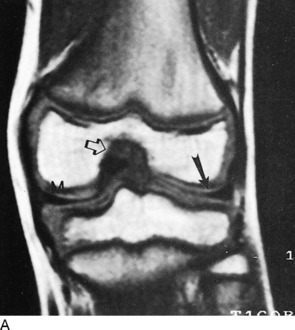
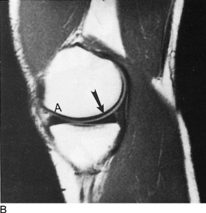
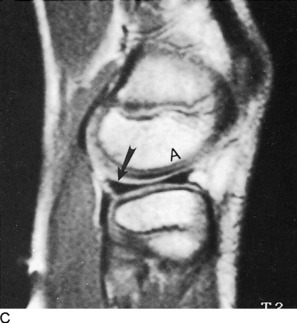
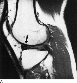
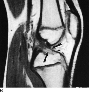
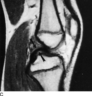
The diagnostic capabilities of MRI in examining the shoulder have only recently been realized because of the development of better designed, dedicated surface coils and updated computer software programs. Although arthrography is still being used and in some instances combined with CT, MRI appears to be taking the same direction as it did in knee evaluations and is becoming more frequently used. Coronal oblique, sagittal oblique, and axial planes of imaging of the shoulder offer a tremendous advantage over other modalities in addition to the use of variable-pulse sequencing protocols, which can be modified to bring out or accentuate subtle findings. Degenerative changes as well as partial or complete tears of the rotator cuff are sensitive to MRI detection (Fig. 16-102).
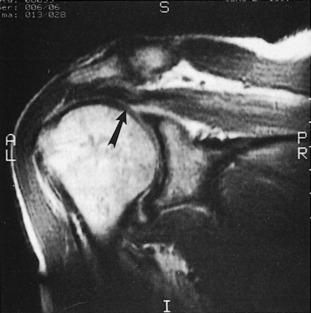
The elbow and ankle can be appropriately analyzed for traumatic abnormalities by MRI (Fig. 16-103). Tears of the Achilles tendon are a prime example, and the severity and extent of the lesion can be properly determined by the magnet. Loose bone or cartilagenous bodies on occasion can be appreciated within joints.
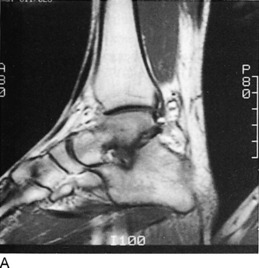
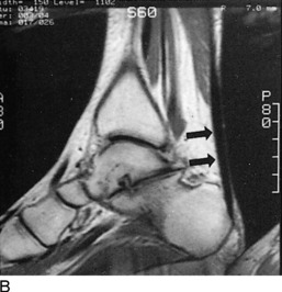
Osteonecrosis
The common denominator in the pathogenesis of both traumatic and nontraumatic aseptic necrosis is vascular compromise. The resultant marrow ischemia, which most often occurs in the growth centers or metaphyseal regions of long bones, provokes an inflammatory response with vascular congestion and edema of the bone marrow.
MRI of osteonecrosis has been determined to be very sensitive and specific early in the disease process. In the femoral head (Fig. 16-104), the images delineate subartic-ular areas of decreased signal intensity (dark). Injuries to the carpal navicular bone, as has been pointed out previously, can defy detection by standard imaging. Appreciation of the process of aseptic necrosis of the proximal navicular fracture fragment requires early detection for best results, and MRI provides a very accurate means to determine this abnormality. Other regions vulnerable to osteonecrosis, such as the humeral head (Fig. 16-105), knee (Fig. 16-106), mandibular condyle, and spine, are easily examined by magnetic imaging.
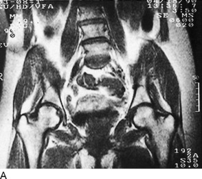
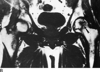
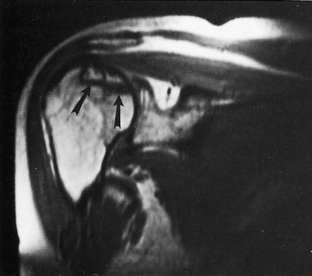
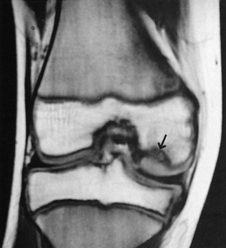
DUAL ENERGY X-RAY ABSORPTIOMETRY AND OSTEOPOROSIS
A number of techniques have been developed over the past few years, the majority of them linked in some way to the computation of the attenuation of ionizing radiation through bone. The first commercially available dual energy x-ray absorptiometer (DEXA) scanner was introduced in 1987, and has since undergone considerable refinement and improvement.
BMD values are expressed as gm/cm2. Measurements are made over the upper four lumbar vertebrae and the left hip (Fig. 16-107). The results are then given as standard deviations or percentile scores. A Z-score is a measure of the difference of the patient’s BMD and the mean BMD for individuals matched by age and sex. A T-score measures the difference in standard deviations of the patient’s BMD and the mean BMD of normal young persons. A fracture risk profile then can be established and appropriate therapeutic measures instituted.

Fig. 16-107 Standard DEXA scan charts for the evaluation of osteoporosis. A, Lumbar spine and B, the hip.
A number of indications have been established for acquiring BMD measurements. Probably the most important is the estrogen-deficient woman. In addition to the postmenopausal female, this can be seen in malabsorption syndromes (celiac disease), poor diet and anorexia, disorders of menstruation, and premature ovarian failure. Illnesses such as Cushing disease, hyperparathyroidism, renal osteodystrophy, and rheumatoid arthritis can lead to osteoporosis. Decreased BMD is also associated with certain drugs such as corticosteroids, anticoagulants, and antineoplastic medications. Also, those with radiographic evidence suggesting osteoporosis (namely, osteopenia with or without spine and hip fractures) are candidates for BMD assessment. Finally, any person being monitored who is on preventive and therapeutic prescription (such as estrogen, alendronate, and raloxifene or calcitonin) meets the criteria for DEXA evaluation of BMD.
Anderson RE. Practical aspects of CT imaging of the spine. Curr Probl Diagn Radiol. 1982;11:1-33.
Beabout JW, McLeod RA, Dahlin DC. Benign tumors of the spine. Semin Roentgenol. 1970;5:419.
Berquist TH. Magnetic resonance of the musculoskeletal system. New York: Raven Press, 1987.
Bisese JH. Orthopaedic MRI: A teaching file approach. New York: McGraw-Hill, 1990.
Blaser SI, Berns DH. Disks, degeneration and MRI. MRI Decisions. 1988;2:23.
Bonnick SL. Bone densitometry in clinical practice. Humana Press, 1998.
Brodeur AE. Radiologic diagnosis in infants and children. St Louis: CV Mosby, 1965.
Brown ML. Bone scintigraphy in benign and malignant tumors. Radiol Clin North Am. 1993;31:731-738.
Caffey J. Pediatric x-ray diagnosis, ed 9. Chicago: Mosby–Year Book, 1993.
Daffner RH. Ankle trauma. Radiol Clin North Am. 1990;28:395-421.
Edeiken J, Cotler JM. Ankle trauma. Semin Roentgenol. 1978;13:145-155.
Edeiken J, Hodes PJ. Roentgen diagnosis of diseases of bone. Baltimore: Williams & Wilkens Co, 1989.
Edelman RR, Siegel JB. Advances in musculoskeletal MRI. MRI Decisions. 1988;2:27.
Forrester DM, Kerr R. Trauma to the foot. Radiol Clin North Am. 1990;28:423-433.
Foster SC, Foster RR. Lisfranc’s tarsometatarsal fracture-dislocation. Radiology. 1976;120:79-83.
Freedman GS. Radionuclide imaging of the injured patient. Radiol Clin North Am. 1973;11:461-477.
Greenfield GB. Radiology of bone diseases, ed 2. Philadelphia: JB Lippincott Co, 1975.
Harris JHJr. Acute injuries of the spine. Semin Roentgenol. 1978;13:53-68.
Harris JHJr, Edeiken J. Acute cervical spine trauma. Radiol Sci Update Series. 1976. No 17,
Holder LE. Bone scintigraphy in skeletal trauma. Radiol Clin North Am. 1993;31:739-781.
Kaye JJ. Fractures and dislocations of the hand and wrist. Semin Roentgenol. 1978;13:109-116.
Kaye JJ, Nance EPJr. Thoracic and lumbar spine trauma. Radiol Clin North Am. 1990;28:361-377.
Kricun R, Kricun ME, Dalinka MK. Advances in spinal imaging. Radiol Clin North Am. 1990;28:321-339.
Lee JKT, Sagel SS, Stanley RJ. Computed body tomography, ed 2. New York: Raven Press, 1989.
Lichtenstein L. Bone tumors, ed 5. St Louis: Mosby–Year Book, 1977.
Littleton JT. Tomography: A current assessment. Curr Probl Diagn Radiol. 1974;4:3.
Mark AS, Atlas SW. MRI of the cervical spine and cord. MRI Decisions. 1988;2:23.
Masaryk TJ. Neoplastic disease of the spine. Radiol Clin North Am. 1991;29:829-845.
Meschan I. Roentgen signs in clinical practice. vol 1. Philadelphia: WB Saunders Co; 1966.
Mirvis SE, Wolf A. Emerging MRI Role: Assessing cervical spine trauma. MRI Decisions. 1990;4:21.
Modic M. Magnetic resonsance imaging of the spine, ed 2. Philadelphia: Mosby–Year Book, 1994.
Moss AA, Gamsu G, Jenant HK. Computed tomography of the body. Philadelphia: WB Saunders, 1983.
Mounts RJ, Schloss CD. Injuries to the bony pelvis and hip. Radiol Clin North Am. 1966;4:307-322.
Newberg AH. Computed tomography of joint injuries. Radiol Clin North Am. 1990;28:445-460.
Pathria MN, Petersilge CA. Spinal trauma. Radiol Clin North Am. 1991;29:847-865.
Patten RM. Musculoskeletal neoplasms: Imaging approach. MRI Decisions. 1989;3:13.
Patten RM, Shuman WP. MRI of osteonecrosis. MRI Decisions. 1990;4:2.
Resnick D. Diagnosis of bone and joint disorders, ed 4. Philadelphia: WB Saunders, 1994.
Rogers LF. Fractures and dislocations of the elbow. Semin Roentgenol. 1978;13:97-107.
Rogers LF. The radiology of sports injuries. Curr Probl Diagn Radiol. 1983;12:1.
Rogers LF, Campbell RE. Fractures and dislocations of the foot. Semin Roentgenol. 1978;13:157-166.
Ross J, et al. Imaging decisions in low back pain. MRI Decisions. 1987;1:16.
Shapiro D. Magnetic resonance imaging of the extremeties. Philadelphia: Mosby–Yeak Book, 1991.
Subbarao K, Jacobson HG. Primary malignant neoplasms. Semin Roentgenol. 1979;14:44-57.
Sze G. MRI of tumor metastases to the leptomeninges. MRI Decisions. 1988;2:2.
Teplick JG, Haskin ME. CT and lumbar disc herniation. Radiol Clin North Am. 1983;21:259-288.
Wilkinson RH, Kirkpatrick JAJr. Pediatric skeletal trauma. Curr Probl Diagn Radiol. 1976;6:1-37.
Zatzkin HR. Trauma to the foot. Semin Roentgenol. 1970;5:419.
[/level-membership-for-orthopaedics-category][not-level-membership-for-orthopaedics-category]
Chapter 16 Radiologic Aspects of Orthopedic Diseases
This chapter contains a radiologist’s viewpoints and suggestions regarding the interpretation of bone roentgenograms. It is hoped this will serve as a useful and practical guide for the busy physician. Principles concerning roentgenographic positioning, anatomy, and pathology are presented by using a regional anatomic approach. Additionally, the musculoskeletal applications of specialized radiologic modalities are discussed. This includes comments on nuclear medicine procedures, diagnostic ultrasound, arthrography, and angiography. Importantly, the imaging technologies of computed tomography (CT) and magnetic resonance imaging (MRI) as they pertain to the evaluation of orthopedic problems are detailed.
General Considerations of Roentgenographic Bone Anatomy
Before beginning a detailed discussion of regional roentgenographic anatomy and pathology, a consideration of pertinent radiologic bone anatomy is important. A bone can be evaluated according to its various components (Fig. 16-1).
APOPHYSIS
There are several apophyses throughout the skeletal system; the best example is the greater trochanter of the proximal portion of the femur. Apophyses do not contribute to bone growth but are considered accessory ossification centers. They tend to appear later than the epiphyses in normal bone development and form protrusions to which ligaments and tendons attach.
BONE VESSELS
There is only indirect evidence of the presence of blood vessels on roentgenograms, and it is the nutrient canals and foramina. They enter the medullary cavity by way of foramina, most often near the midshaft of a long bone, and result in radiolucent channels. When viewed on the roentgenogram, these channels can be confused with a fracture. Prominent nutrient canals frequently are seen in the diaphyses of the femur and tibia. Y-shaped nutrient canals occur in the midportion of the iliac bones of the pelvis and in the subspinous region of the scapulae.
Analytic Approach to Bone Changes
SPECIFIC PARAMETERS
Certain specific parameters of bone need careful attention. In the process of evaluating these, using a systematic approach can lead to a logical conclusion. Among the criteria to be analyzed are an increase or decrease in bone density, alterations in osseous texture (trabecular pattern), periosteal reactions, and the conditions of the cortex, endosteum, and medullary spongiosa. If any changes of these are observed, then the abnormality should be studied in terms of its size and configuration and the sharpness of its margins (transition zone). The specific bone involved and the position of the lesion within that bone (epiphysis, metaphysis, or diaphysis) should also be noted. For example, leukemia, metastatic neuroblastoma, a benign simple cyst, and Brodie’s abscess have a predilection for the metaphysis, whereas a chondroblastoma typically involves the epiphysis.
This is a simple, general outline, and many more particulars come into play. By developing this type of approach, the many clues offered will help to determine the nature of the pathologic process and place the lesion into a certain category (for example, benign, malignant, infectious, traumatic, or metabolic). Table 16-1 lists some of the specific characteristics of different bone lesions.
Table 16-1 General Characteristics of Different Bone Lesions
| Characteristics of benign bone lesions |
| Sclerotic margins (narrow transition zone) |
| Homogeneous periosteal reaction |
| Expansion of an intact cortex |
| Characteristics of solitary malignant bone lesions |
| Permeative or moth-eaten destruction (wide transition zone) |
| Irregular, sometimes spiculated periosteal reaction |
| Preferential metaphyseal location |
| Extraosseous extension with soft tissue mass and occasional fluffy calcifications |
| Characteristics of metastatic lesions |
| Absence of periosteal reaction |
| Moth-eaten destruction of medulla and cortex |
| Preferential diaphyseal location |
| Pathologic fractures |
| Multiple bone involvement |
| Characteristics of infection |
| Often irregular periosteal reaction, no spiculation |
| Bone destruction variable |
| Diaphyseal involvement, often involving long segments |
| Destruction of adjacent cartilage, crossing joints (majority of malignant neoplasms lack this ability) |
| Sequestration and involucrum formation |
PATTERNS OF BONE DESTRUCTION
TYPES OF PERIOSTEAL REACTIONS
When the outer periosteal membrane of bone is irritated, its constituent osteoblastic cells react by producing new bone. This new bone can take on either a solid or an interrupted appearance, and the specific form can assist in identifying the inciting cause (Table 16-2). Solid periosteal reactions are usually indicative of a benign process. The new bone is consistently uniform in density. As seen in Table 16-2, the thickness and marginal characteristics vary according to the precipitating factor.
| Types | Examples |
|---|---|
| Solid periosteal reaction | |
| Thin | Eosinophilic granuloma, osteoid osteoma |
| Thin undulating | Hypertrophic pulmonary osteoarthropathy |
| Dense undulating | Vascular |
| Dense elliptical (with destruction) osteoid osteoma | |
| Cloaking | Long-standing malignancy |
| Chronic infection | |
| Interrupted periosteal reaction | |
| Perpendicular (spiculated or sunburst) | Osteosarcoma, Ewing’s sarcoma, infection |
| Lamellated (onion skin) Osteosarcoma, | Ewing’s sarcoma, infection |
| Amorphous | Malignant tumors |
| Codman’s triangle | Malignant tumors, infection, hemorrhage |
* From Edeiken J, Hodes PJH: Roentgen diagnosis of diseases of bone, Baltimore, 1967, Williams & Wilkins. Used by permission.
The interrupted forms of periosteal reactions are more commonly found in malignant disease, although benign lesions such as infection are occasionally responsible. The classic spiculated or sunburst pattern of osteogenic sarcoma and the lamellated or onion skin, periosteal reaction of Ewing’s sarcoma come under this heading (see Table 16-2).
Regional Anatomic and Pathologic Roentgenography
CERVICAL SPINE
ROENTGENOGRAPHIC EXAMINATION
The standard roentgenographic views of the cervical spine include anteroposterior, lateral, and both posterior oblique views, as well as an open-mouth anteroposterior projection of the odontoid process and the first two cervical vertebral segments (Fig. 16-2). The majority of cervical spine studies are performed for the evaluation of trauma. In the more severely injured individual, the most important views are a cross-table horizontal beam lateral image and an anteroposterior supine film. By keeping patient movement to a minimum, potentially fatal spinal cord injury is prevented.
Dr. Don Weir of Saint Louis University developed the “pillar view” for better evaluation of the lateral articulating masses, the superior and inferior articulating facets, and their intervening joints. Moreover, this view brings into focus the anterior and posterior margins of the lamina (Fig. 16-3). The film is produced with the patient supine. Each side is done separately. The head is turned very slightly to one side, with the roentgenograph tube angled toward the feet 35 to 45 degrees and centered over the middle to lower vertebrae. The opposite side is then examined in a similar manner.
ROENTGENOGRAPHIC ANATOMY
A thorough understanding of the roentgenographic anatomy of the cervical spine is an absolute prerequisite to its proper evaluation. Each component of the individual vertebrae should be appraised separately on all views.
Odontoid View
Of the seven cervical vertebrae, the first two are anatomically distinct. The odontoid represents a superior extension of the body of C2 and is actually the vestigial body of C1. On the anteroposterior open-mouth film, the odontoid should be analyzed in terms of its position between the two lateral articulating masses of C1 (see Fig. 16-2, D). The spaces between the lateral edges of the odontoid and the medial borders of the C1 articulating masses should be equal. However, minor degrees of rotation can produce spurious inequality of these interval distances. How can this be determined? The alignment of the densities of the spinous processes of C1 and C2 can be seen. If the C2 spinous process is to one side or the other, then rotation is present.
Also on viewing the odontoid film, the transverse processes and lateral borders of the articulating masses of C1 and C2 should not be overlooked. The horizontal joints between the atlantoaxial articulating masses should be symmetric (see Fig. 16-2, D).
Confusing artifacts superimposed on the odontoid can be misleading and can result in misinterpretation of fractures of this structure. The inferior margin of the anterior or posterior arch of C1 can overlie the base of the odontoid and create a “Mach” effect, a radiolucent line produced by overlap of the edges of two bones. In a similar fashion, the space between the two incisor teeth may lay over the odontoid and yield an artifactual vertical cleft (Fig. 16-4).
It is not unusual for the odontoid process to be completely obscured by the base of the occipital bone if the head is held too far in extension. In such circumstances, have the view repeated with the patient’s head slightly more flexed.
Lateral View
Several important points must be remembered when viewing the lateral projection of the cervical spine (see Fig. 16-2, B). Alignments of the anterior and posterior borders of the vertebral bodies, alignment of the lateral articulating masses, and alignment of the spinolaminar line are studied. The latter is formed by the anterior margins of the spinous processes, which also describe the posterior surface of the spinal canal. The superior extension of this line is in direct alignment with the posterior margin of the foramen magnum.
The superior and inferior articulating facets ordinarily are well visualized on the lateral film. The posterior borders of the lateral articulating masses should form a straight line (see Fig. 16-2, B). If there is a slight offset, a facetal dislocation must be considered, although slight rotation can give a similar appearance. The view should be repeated if there is any confusion, and if the problem persists, CT scanning should be considered.
Oblique Views
The intervertebral foramina and surrounding elements, including the pedicles and uncinate processes, are the most important components demonstrated on the oblique views. The foramina on the right side are visualized on the left posterior oblique projection and those on the left on the right posterior oblique film (see Fig. 16-2, C).
TRAUMA
Recognition of an abnormal cervical spine should be a relatively simple task once normal roentgenographic anatomy has been mastered. After a traumatic lesion has been identified, the primary objective is the establishment of whether the condition is stable. The stability of a fracture is best determined by grouping the type of injury according to the mechanisms of trauma, which are outlined in Table 16-3. From this classification, a statement of the instability of the injury can be made (Table 16-4).
Table 16-3 Classification of Cervical Spine Injuries According to the Mechanisms of Injury*
| Flexion |
| Subluxation |
| Bilateral interfacetal dislocation |
| Simple wedge fracture |
| Flexion teardrop fractures |
| Clay-shoveler’s fracture |
| Flexion-rotation |
| Unilateral interfacetal dislocation |
| Vertical compression |
| Bursting fractures |
| Jefferson’s C1 |
| Bursting fractures, other levels |
| Extension |
| Posterior neural arch fracture |
| Extension teardrop fracture |
| Hangman’s fracture |
* From Harris JH Jr: Acute injuries of the spine, Semin Roentgenol 13:53–68, 1978. Used by permission.
Table 16-4 Classification of Cervical Spine Injuries Based on Stability*
| Stable |
| Subluxation |
| Simple wedge fracture |
| Unilateral interfacetal dislocation |
| Bursting fracture, except Jefferson’s fracture of C1 |
| Clay-shoveler’s fracture |
| Unstable |
| Bilateral interfacetal dislocation |
| Flexion teardrop fracture |
| Jefferson’s bursting fracture of C1 |
| Hangman’s fracture |
| Extension teardrop fracture, unstable in extension but stable in flexion |
* From Harris JH Jr: Acute injuries of the spine, Semin Roentgenol 13:53–68, 1978. Used by permission.
Flexion Injuries
There are a variety of flexion injuries, which are described below.
Subluxation
The roentgenographic findings in this stable lesion may be minimal, often requiring flexion and extension lateral views for confirmation. The body and posterior elements remain intact; that is, show no fracture. However, there is major soft tissue involvement. The interspinous and posterior longitudinal ligaments, as well as the interfacetal joint capsules, are disrupted at the affected level. This allows the involved vertebral body to rotate anteriorly about its anterior and inferior corner, along with upward and forward displacement of its inferior articular facet on the lower adjacent vertebra’s superior articular facet. The interspinous distance widens, and the inferior intervertebral disc space narrows anteriorly and widens posteriorly. These alterations are accentuated on the flexion film (Fig. 16-5). In children younger than 8 years, with the head held in flexion, the second cervical vertebra is normally displaced anteriorly over C3. This malalignment must not be mistaken for subluxation.
Clay-Shoveler’s Fracture
This lesion is named for the injury acquired by people in occupations that require heavy lifting. This injury consists of a fracture through the spinous process of either C6 or C7 (Fig. 16-6). There is no significant ligamentous damage, and therefore a stable condition exists. Because C7 is sometimes difficult to project on the lateral film, the fracture can be missed. A clue might be apparent on the frontal film, where an extraspinous process fragment is sometimes evident as the result of inferior displacement. An unfused apophysis of a spinous process must not be misinterpreted as a fracture (Fig. 16-7).
Flexion-Rotation Injuries
When the cervical spine is subjected to a rotational force in addition to flexion, a unilateral interfacetal dislocation may be observed (Fig. 16-8). An inferior articular facet of one body is displaced over the adjacent superior articular facet of the next inferior vertebra on one side only. The dislocated facet is more or less locked in place, but because of associated ligament damage, the lesion may be unstable; therefore, flexion and extension views are contraindicated. Oblique projections are most productive in identifying the displaced facet, but it may be suggested on the lateral film when the margins of the facets of a single vertebra do not superimpose on one another as the result of rotation. Additionally, a line drawn through the posterior borders of the bodies is offset at the level of the suspected injury.
Extension Injuries
Various extension injuries are described as follows.
Posterior Neural Arch Fractures
The neural arch of one vertebra may be compressed between the posterior elements of the two adjoining vertebrae during maximal forced extension. A unilateral or bilateral fracture may be sustained. If bilateral, the fragment can be displaced posteriorly, yet there will be no encroachment on the neural canal; thus, the situation is a stable one (Fig. 16-9).
Extension Teardrop Fracture
Similar to the flexion variety, an extension teardrop fracture demonstrates a triangular-shaped fragment at the anterior-inferior margin of the body, most often involving C2, although other levels are affected (Fig. 16-10). However, the injury is not quite as severe, because there is no posterior involvement. When the neck is held in flexion, there is stability of the spine because the posterior ligament complex is intact. However, instability occurs during extension because the minor fragment remains attached to the anterior longitudinal ligament but not to the parent body.
Hangman’s Fracture-Dislocation of C2
This lesion consists of vertical disruption of both pedicles of C2 and is created by flexion forces against the extended vertebrae. The body of C2 is thrust forward over C3, with concomitant rupture of both the anterior and the posterior longitudinal ligaments, giving rise to an unstable injury (Fig. 16-11).
Vertical Compression Fractures
A considerable force directed through the vertical axis of the spine (such as a large object falling on top of the head or a diving injury) can produce the so-called bursting fractures of the cervical vertebrae. The least common type is the Jefferson fracture of C1. The anterior and posterior aspects of the ring are fractured on both sides, with bilateral lateral displacement of the fragments. This unstable injury can be apparent on the open-mouth anteroposterior film but more reliably is distinguished on the lateral roentgenogram where the fractures are seen to extend through the posterior arches.
THORACIC AND LUMBAR SPINE
Roentgenographic Anatomy
Anteroposterior View
On the anteroposterior projection, the spinous processes provide another guide for the evaluation of alignment. Rarely, they may be absent because of aplasia or malignant or infectious destruction.
Oblique Views
Important anatomic features are introduced on the oblique views of the lumbar spine. These details have been covered more extensively in Chapter 8. On the left posterior oblique film (left side down against the film), the left half of the posterior neural arch elements, including the intervertebral foramina, are identified, whereas the right half of these components are viewed on the opposite projection. In the cervical spine, the reverse condition exists.
DEVELOPMENTAL VARIATIONS AND CONGENITAL ABNORMALITIES
Confusing anatomic variations are seen in the developing and mature spine. In infancy, the vertebral bodies are egg-shaped on lateral view. The upper and lower anterior corners are beveled until the apophyseal vertebral rings appear about each end plate. They fuse with the body by the fifteenth year, but occasionally they remain ununited and, except for the presence of a complete sclerotic border, often are confused with a corner fracture (Fig. 16-12). These are sometimes referred to as limbus vertebrae.
Fig. 16-12 An unfused ring apophysis of a lumbar vertebra as seen here can be confused with a fracture.
On the anteroposterior film, a vertical radiolucent cleft is seen superimposing on the vertebral bodies (Fig. 16-13). This represents the normal uncalcified portion of the posterior neural arch and spinous process and is not to be confused with spina bifida. At approximately 3 to 5 years of age, these will ossify and fuse. When they do fail to fuse completely, the cleft persists as a spina bifida occulta. This can occur anywhere in the spine, but is most common at L5. These are of no clinical importance.
Hypoplasia of the vertebrae, fusion or block vertebrae, and hemivertebrae constitute a few of the other possible spinal anomalies (Fig. 16-14).
TRAUMA
Another important traumatic lesion, particularly of the lumbar spine, that can be easily overlooked is the transverse process fracture (Fig. 16-15). The importance of its recognition rests with the fact of frequently related renal injury. It is important not to mistakenly call the unfused apophysis of the transverse process a fracture.
A seldom-seen injury to the lumbar vertebrae is the Chance fracture (Fig. 16-16). An extreme flexion force, often related to seat belt injuries, causes a fracture through the spinous process, across the neural arch or lamina, and into the posterosuperior aspect of the vertebral body. An isolated fracture of the spinous process is uncommon in the thoracic and lumbar regions.
One more pitfall to watch for in the assessment of spinal trauma is the unfused ossification center of the articular facets, which can resemble a fracture (Fig. 16-17). In evaluating the posterior elements, it is important to keep in mind the entities of spondylolysis and spondylolisthesis (see Chapter 8).
TUMORS
Hemangioma
Hemangiomas of the vertebral body may be the most common benign tumor, although few have been documented pathologically. Typically, their appearance is that of increased vertical trabeculations producing a somewhat striated pattern (Fig. 16-18). They should not be confused with Paget’s disease or osteoblastic metastasis.
Aneurysmal Bone Cyst
Of the benign tumors of the spine, aneurysmal bone cysts are possibly the next most frequent after hemangiomas. They are more commonly found in the extremities, especially the distal portion of the femur. In the spine, they tend to involve the posterior elements as well as the body. Possessing a thin shell of peripheral bone, they are expansile and cystic in nature. Roentgenographically, a malignant appearance can be seen with a predominant cystic pattern. Unlike other tumors, benign and malignant alike, aneurysmal bone cysts have the unique capability of crossing over the cartilaginous disc space to involve adjacent vertebrae. A malignant chordoma also has this potential.
Hodgkin’s Lymphoma
Hodgkin’s disease can occasionally be seen within the bony spine and may present as an osteolytic or osteoblastic alteration or a combination of the two. However, more commonly, paraaortic lymph node involvement with lymphoma produces erosive changes of the vertebral cortical margins.
INFECTION
In both pyogenic discitis and vertebral osteomyelitis, the earliest roentgenographic findings may be joint space narrowing. Depending on the aggressiveness of the offending bacteria and the time of institution of therapy, the surrounding bone shows varying degrees of demineralization brought on by hyperemia. The end plates then demonstrate progressive loss of continuity with irregular destruction and focal areas of subchondral reactive sclerosis. Extension into the posterior third of the body, then into the dorsal appendages, as well as into the adjoining vertebrae, may occur. The body may eventually collapse. Some degree of surrounding soft tissue swelling is invariably present and detectable on roentgenograms and corroborated on MRI (Fig. 16-19).
Because of its insidious and chronic nature, the spinal lesions are usually advanced when first examined roentgenographically, although this is not always the situation. An occasionally prominent feature is a large paravertebral soft tissue mass that constitutes the abscess. In later phases, there may be extensive calcification within this mass (Fig. 16-20). The bony structures show a decrease in density, and there is narrowing of one or more of the disc spaces. The margins of the end plates manifest irregular destruction, and a mottled sclerotic and lytic appearance extends into the bodies, which display varying degrees of compression.
SPINAL ARTHRITIS
Arthroplasty of spondylosis of the spinal column most commonly is degenerative in nature with the formation of hypertrophic bony spurs. These osteophytes are formed by recurrent stimulation of wear and tear factors, and are predominantly located along the end-plate margins of the vertebral bodies. When they bridge the interspaces and fuse, such spurs are described as syndesmophytes, which can more often be identified in specific forms of arthritis, such as diffuse idiopathic skeletal hyperostosis (DISH; Fig. 16-21).
Ossification of the anterior longitudinal ligament of the spine is characteristic of ankylosing spondylitis (Marie–Strümpell disease). Psoriatic arthritis, Reiter disease, and other autoimmune diseases (including inflammatory bowel diseases) may lead to exuberant osteophyte formation.
PAGET’S DISEASE
One of the distinctive roentgenographic characteristics of spinal Paget’s disease is that the disorder involves the entire vertebra—the body and all of the posterior elements, including the transverse and spinous processes (Fig. 16-22). Generally, there is an increase in density produced by a thickened trabeculae. A picture frame appearance can be imparted to the body, the result of a dense peripheral margin of thickened cortex. Furthermore, there is an actual increase in volume of the entire vertebra. This finding, along with total vertebral involvement, distinguishes Paget’s disease from an osteoblastic metastasis.
THE SHOULDER
ROENTGENOGRAPHIC EXAMINATION
In the majority of cases, a complete and optimal roentgenographic study of the shoulder girdle needs only include upright—standing or sitting—anteroposterior views with the humerus in internal and external rotation. These two projections usually permit adequate evaluation of the bony structures constituting the shoulder. In the uncooperative child or severely traumatized patient, these films may be obtained while the patient is in the supine position. On these roentgenograms, the complete clavicle should be visualized in addition to the entirety of the scapula and at least the proximal third of the humerus. Special attention should be given to the alignments of the glenohumeral, acromioclavicular, coracoclavicular, and sternoclavicular joints. The tuberosities of the humeral head and its articular surface should be specifically scrutinized. The acromium and coracoid processes, in addition to the borders and flat surfaces of the scapula, require attention.
When there is suspicion of a fracture involving the shaft of the humerus below the neck, in addition to an anteroposterior view, a transthoracic lateral projection is necessary for evaluation of alignment (Fig. 16-23). The glenohumeral relationship can also be accessed with proper exposure, but because of superimposed ribs, fractures above the neck are difficult to see. Instead, a transscapular study is more helpful (Fig. 16-24). This view is obtained by having the patient face the film at an angle of 45 degrees with the affected side toward the film holder. The resultant picture forms a Y where the acromium, coracoid, and scapular body intersect. The humeral head will be superimposed on the Y. This is useful not only for fractures but also for posterior dislocations. This transscapular examination is always used when studying the scapula, in addition to the routine anteroposterior roentgenogram. CT or MRI imaging, particularly the latter, can provide additional valuable information especially regarding soft tissue involvement. The multiplanar capabilities of these imaging modalities augments visualization of gross pathologic findings.
Posterior shoulder dislocations are notorious for their ability to avoid detection on the standard anteroposterior views; they are frequently associated with seizure disorders. The tangential projection is an excellent means for detecting the abnormality. This is performed by angling the roentgen tube approximately 30 degrees so that the central ray passes tangentially across the glenoid articular surface. In this manner, the glenohumeral relationship is much better defined than on the conventional straight anteroposterior view.
The axillary film also provides another perspective of the shoulder anatomy (Fig. 16-25). The acromium, coracoid, glenohumeral joint, and humeral head are viewed in a different plane. By holding the film against the top of the shoulder, the picture is produced by abducting the arm and centering the roentgen tube through the axilla. The study requires a special “grid” cassette for the film. It is helpful in determining the presence of a humeral head displacement, but it is not recommended when a dislocation has just been reduced, because the required abduction may reluxate the joint.
A more difficult area to examine roentgenographically is the sternoclavicular joint. Because of bony superimposition, CT may be required, but because this is not universally available, both oblique and lateral views may suffice. However, if these attempts are unsuccessful, the patient can be positioned prone. The roentgen tube is then centered through the sternoclavicular joints and angled toward the head at a 35-degree tilt.
ROENTGENOGRAPHIC ANATOMY AND DEVELOPMENTAL VARIATIONS
A considerable degree of confusion can be created by the ossification centers of the shoulder. The proximal humeral epiphysis does not become visible, as a rule, until the fourth to eighth month of life. There are two, occasionally three, separate centers. By the age of 20, the proximal epiphysis fuses to the shaft of the humerus. Before complete closure of the epiphyseal suture, the lucent line has a peculiar angulated appearance (Fig. 16-26). Overlap of the suture line occurs no matter what projection is used and consequently produces an image simulating a fracture.
TRAUMA
Of all the joints in the body, the shoulder is the most frequent site of dislocations. More than 97% are anterior and can be described as subglenoid or subcoracoid, depending on the location of the humeral head. Invariably, this form of dislocation can be visualized by a single anteroposterior roentgenogram (Fig. 16-27). Whenever a dislocation occurs, it is not unusual to have an associated fracture; this should be searched for on the film. With an anterior dislocation, a fracture of the greater tuberosity may exist; the lesser tuberosity is vulnerable in posterior dislocations. The lower glenoid margin is also susceptible in either type of dislocation. An infraction of the articular cartilage without a visible fracture is also possible in dislocations and may require MRI to demonstrate.
With chronic recurring anterior dislocations, a defect becomes apparent along the superolateral aspect of the humeral head. This cortical infraction, present because of impaction against the anteroinferior rim of the glenoid, is commonly referred to as Hill–Sachs deformity. This abnormality is usually best demonstrated on an internally rotated anteroposterior view (Fig. 16-28).
The less frequent posterior dislocation is much more difficult to visualize roentgenographically. The problem arises because the humeral head on the standard anteroposterior projections shows no apparent separation from the glenoid fossa when in fact it is separated. The posterolateral orientation of the glenoid articular surface accounts for this to some extent. Ordinarily, in the normal shoulder the head of the humerus overlaps about three fourths of the glenoid fossa. When it becomes posteriorly dislocated because of lateral displacement of the head, this overlap is less, but the change may be very subtle. This perplexing situation can usually be solved by using the 30-degree tangential view, the axillary projection, or the transscapular film (Fig. 16-29). With recurrent posterior dislocations of the shoulder, a defect of the inferoposterior cartilagenous labrum may not be visible by stand-ard radiography. This is termed a Bankart lesion, which can be diagnosed by MRI or CT arthography.
A very rare form of dislocation of the shoulder joint is luxatio erecta, a condition where the humeral head is located under the glenoid rim and the humeral shaft is directed above the head in fixed abduction (Fig. 16-30). A lateral fall on an elevated arm produces such an abnormality. The acromium process of the scapula acts as a fulcrum pushing the head of the humerus down and out of the glenohumeral joint. The dynamics of the applied forces can result in a fracture of the acromium, the lower lip of the glenoid, or the greater tuberosity of the humerus. Often, there is an associated tear of the rotator cuff.
Transverse subcapital fractures of the surgical neck along with avulsions of the greater tuberosity are the most commonly encountered injuries to the shoulder. A fracture-displacement of the ununited epiphysis creates a more difficult diagnostic challenge. The normal epiphyseal line itself, as already mentioned, makes interpretation troublesome. The normal epiphysis has a uniform width and dense margins, whereas a fracture demonstrates varying thickness with a sharp, nonsclerotic edge. Often, there is impaction or distraction of the fragments causing some degree of overlapping, which makes the diagnosis somewhat simpler. Of course, if the presence of an abnormality is uncertain or indeterminate, an accurate comparison with the opposite uninjured shoulder should be performed.
TUMOR
The proximal aspect of the humerus is a relatively common location for a benign solitary cyst, which may appear as either simple or multiloculated (Fig. 16-31). Such cysts are found within the metaphysis and exhibit destruction of the medullary spongiosa with more or less expansion of the bone. Thinning of the cortex can attain paper thickness, and pathologic fractures are a very common event, even in the absence of significant trauma. When initially discovered, the cysts extend to the epiphyseal line but do not involve the growth center itself. When followed serially until fusion of the epiphysis, the cyst appears to “migrate” toward the middle of the shaft as growth of the bone ends progresses.
[/not-level-membership-for-orthopaedics-category]
