CHAPTER 3 Radiographic Evaluation and Classification of Distal Radius Fractures
X-rays are essential to the treatment of distal radius fractures. When combined with the age and baseline level of activity of the patient, the interpretation of a patient’s x-rays significantly influences the type of treatment selected. Radiographs form the basis for nearly every system of classification of distal radius fractures. Radiographs also are used during procedures to judge residual fragment displacements and to determine whether hardware has been placed appropriately. Ultimately, x-rays are the means used to assess the quality of the final reduction and treatment.1 By improving the interpretation of standard x-rays, a better understanding of the pattern of injury emerges, which improves algorithms for treatment and ultimately results in better clinical outcomes.
Radiographic Landmarks
Posteroanterior View
The actual x-ray technique directly affects the quality and characteristics of the visual information that is presented on the radiographic image. It is not unusual to receive injury films that have been poorly positioned or were taken with poor radiographic technique from emergency staff members who were unwilling to move an injured arm for fear of causing additional pain or injury to the patient. X-rays of an unreduced, highly displaced fracture compound the difficulties of interpretation because of the distortion from abnormal displacement and rotation of fracture components. In some cases, determining the nature of a complex injury is no more complicated than simply obtaining a second set of films after a closed reduction with proper positioning and technique. Finally, articular visualization on the PA view may be improved by angling the x-ray beam 10 degrees proximally.2
The rotational position of the forearm also can change the appearance of the radiographic image (Fig. 3-1).3 On a standard PA view of the wrist with the forearm in neutral position, the cortical bone along the ulnar border of the ulnar styloid connects smoothly with the cortical bone along the ulnar border of the shaft. In addition, the cortical outline of the ulnar head does not extend behind the ulnar styloid, and the lateral border of the distal ulnar shaft has a concave outline on its radial side. Subtle changes occur if this view is taken with the forearm in full supination (typically done as an anteroposterior [AP] view). In this situation, the position of the ulnar styloid shifts radially to align more toward the central longitudinal axis of the ulnar shaft. In addition, the ulnar shaft shows a more linear appearance along its radial border, and the subchondral bone of the ulnar head can be seen superimposed over the ulnar styloid.
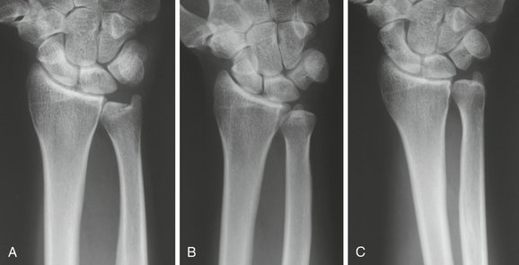
With the forearm in a position of full pronation, the radius crosses over the ulna resulting in an obligate but physiological shortening of the radius in relation to the ulna. In this position of forearm rotation, a normal loss of about 0.5 mm of radial length is common. In addition, the radial and ulnar shafts appear to converge proximally, and the cortical outline of the ulnar head can be identified behind the base of the ulnar styloid. With pronation of the forearm, measured values of radial inclination, volar tilt, and radial height decrease; with supination of the forearm, these values increase.4
The carpal facet horizon is a radiodense line that appears on a normal PA view near the distal articular surface and extends from the ulnar side of the radius across most of the width of the bone (Fig. 3-2). In a normal wrist, the carpal facet horizon is inclined at an angle of about 10 degrees to a perpendicular of a line extended from the longitudinal axis of the radius. The carpal facet horizon is a radiographic landmark that is produced by the x-ray beam as it crosses a portion of the curved arc of dense subchondral bone that is tangential to the axis of the beam. Because a normal distal radius has a volar tilt of 5 to 8 degrees, under normal circumstances, the volar portion of the subchondral plate is the part of the articular surface that is parallel to the x-ray beam. As a result, in a PA view of a normal wrist, the carpal facet horizon identifies the volar rim of the lunate facet and extends ulnar to the volar corner of the sigmoid notch.
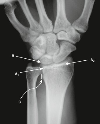
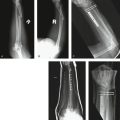
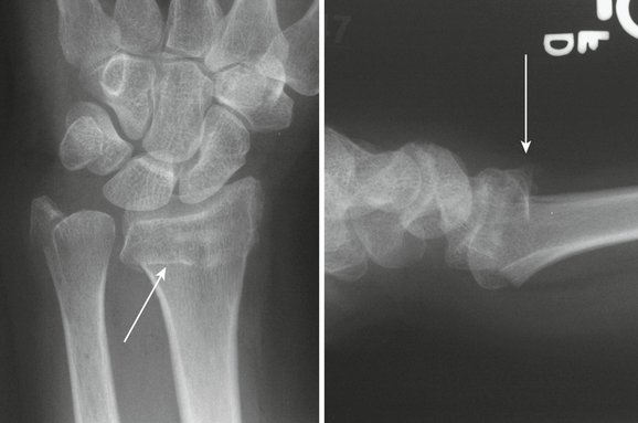
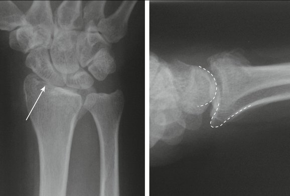
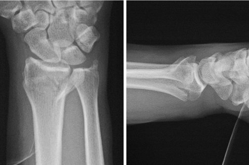
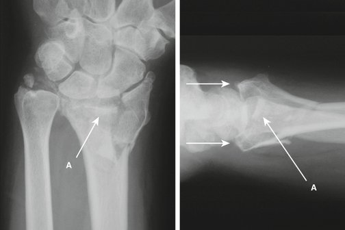
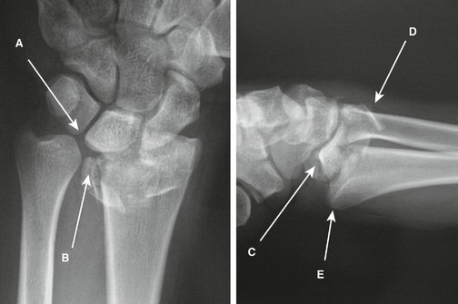
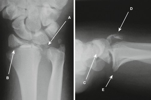
Identification of the carpal facet horizon has several clinical applications. Discontinuity of this landmark suggests the presence of a separate intra-articular fracture component. Isolated volar shear fractures with proximal and volar displacement of a free volar rim fragment can show an obvious step-off in the carpal facet horizon on the PA projection and imply the presence of an articular fragment (Fig. 3-3). The carpal facet horizon also is used to identify whether a particular fragment on the PA view involves the dorsal rim or volar rim. In fractures that are volarly displaced in which there is volar tilt of the articular surface on the lateral x-ray, the carpal facet horizon identifies the volar rim of the lunate facet. In fractures that are dorsally displaced in which there is dorsal tilt of the articular surface on the lateral x-ray, the carpal facet horizon identifies the dorsal rim of the lunate facet. Determining whether a particular articular fragment is located dorsally or volarly on the PA view can be crucial in assessing the pattern of instability and in considering surgical approaches (Fig. 3-4).
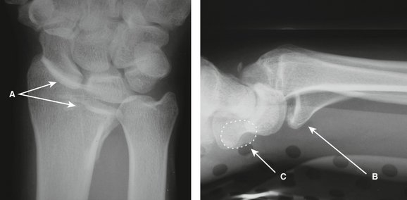
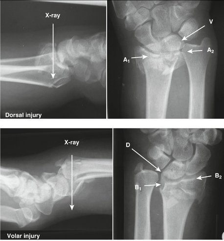
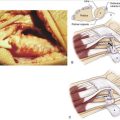
FIGURE 3-4 Clinical Application of the Carpal Facet Horizon. Top panel, In the dorsal injury, the distal fragment has rotated dorsally causing the dorsal portion of the subchondral bone to align with the axis of the x-ray beam. In this case, the carpal facet horizon (A1-A2) identifies the dorsal rim of the lunate facet. Note the position of the dorsal ulnar corner (A2) and the volar corner of the sigmoid notch (V). Discontinuity of the carpal facet horizon indicates an additional free articular fragment. Bottom panel, In the volar injury, the distal fragment has rotated volarly. As a result, the volar rim of the lunate facet is aligned with the x-ray beam, and the carpal facet horizon (B1-B2) identifies the volar rim. Note the position of the volar corner (B1) and dorsal corner (D) of the sigmoid notch. Also note the irregularity of the carpal facet horizon indicating a separate volar rim and radial column fragment.
Lateral View
The lateral x-ray is normally taken with the forearm in neutral rotation. The accuracy of obtaining a true lateral film can be checked by noting the position of the pisiform in relation to the distal pole of the scaphoid on the lateral view. On a true lateral x-ray, the pisiform is located directly over the distal pole of the scaphoid (see Fig. 3-3). If the pisiform lies dorsal to the distal pole of the scaphoid, the forearm is rotated into pronation, and the x-ray is more oblique. Although this type of oblique view can put the volar portion of the radial column in profile, it also results in suboptimal visualization of the volar rim.
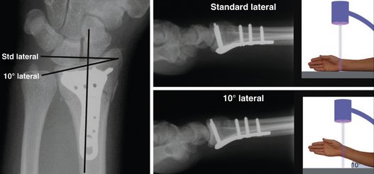
In addition to a standard lateral view, the 10-degree lateral view provides a sharper image of the articular surface. The 10-degree lateral view is so named because the ulnar two thirds of the articular surface is normally at an inclination of about 10 degrees to a perpendicular of a line extended along the longitudinal axis of the radius. In some patients, this angle may be greater to correspond to variations in the tilt of the ulnar two thirds of the articular surface.5,6 The technique for taking the 10-degree lateral view is simple. The forearm is initially positioned horizontally on the plate as if to take a standard lateral x-ray and then elevated 10 degrees off the horizontal plane. If done properly, the articular outline of the ulnar two thirds of the radiocarpal joint is placed into sharp relief (Fig. 3-5). This view positions the outline of the radial styloid more proximally than is normally seen on the standard lateral view and may affect the appearance of hardware placed on or into the radial styloid.
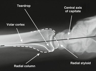
The teardrop is a dense, U-shaped outline seen at the distal end of the radius on the lateral view; it is formed from the confluent outlines of the distal shaft and distal radial ridge, and terminates in the volar rim of the lunate facet (Fig. 3-6). The thickness of the cortical bone that forms the base of the teardrop is noted to be significantly greater than the thickness of the dorsal cortical bone and reflects the greater loading forces that normally occur along the volar surface of the radius. In addition, a line that extends from the volar cortex of the radial shaft nearly bisects the curve of the articular surface (typically passing just volar to the center of the articular surface on the lateral view), suggesting that the carpal load is nearly balanced along the volar cortex.
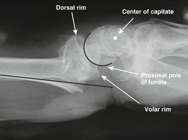
The distal articular surface of the radius on a normal wrist has an arc of curvature that matches the arc of curve of the proximal pole of the lunate; this uniform joint interval is more clearly seen on the 10-degree lateral x-ray. Fractures that result in a joint interval that is nonuniform from the dorsal to volar margin or show incongruent arcs of curvature between the articular surface of the distal radius and the proximal pole of the lunate imply discontinuity between the volar and dorsal joint surfaces with independent articular fracture components (Fig. 3-7).
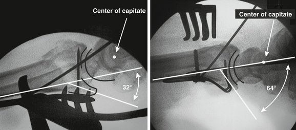
Carpal alignment also is an important feature to observe on the lateral x-ray. With a wrist in neutral to slight dorsiflexion, a line extended from the volar cortex of the radial shaft should be nearly collinear with the center axis of rotation of the proximal pole of the capitate (see Fig. 3-6). Fractures with dorsal angulation or displacement cause translation of the carpus dorsally, resulting in dorsal migration of the proximal pole of the capitate relative to the volar cortex of the radial shaft (Fig. 3-8). Fractures that displace to the volar side result in volar migration of the capitate from its normal alignment with the radial shaft and are highly unstable. Significant displacement of the carpus in either direction changes the functional moment arm of tendons that cross the wrist and may contribute to adverse affects on grip strength.
Radiographic Parameters
Anteroposterior View
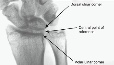
Radial inclination and ulnar variance are two parameters measured on the PA view that often are defined using the most distal corner of the ulnar border of the distal radius as a point of reference. As discussed previously, this radiographic landmark does not correspond to a single anatomical structure, but may vary, representing either the dorsal corner of the sigmoid notch or the volar corner of the sigmoid notch depending on whether the distal articular surface has a volar or dorsal tilt. Because these measurements should ideally remain independent of the tilt of the articular surface on the lateral view, a central reference point (CRP) should be used for the measurement of radial inclination and ulnar variance. The CRP can be identified by determining the center of a line that is drawn between the volar and dorsal corners on the AP view (Fig. 3-9). Because the CRP coincides with the coronal center of the distal edge of the sigmoid notch, it is relatively independent of changes in the volar tilt of the articular surface. Using the CRP is particularly important for assessing ulnar variance because this measurement can be significantly affected by changes in volar tilt.
Radial inclination is a parameter that is defined as the angle between a line drawn from the tip of the radial styloid to the CRP and a line perpendicular to the long axis of the radius (Fig. 3-10). In normal wrists, radial inclination measures about 24 degrees.7 Generally, displaced fractures of the distal radius reduce radial inclination; radial inclination less than 15 degrees is a relative indication for operative treatment.
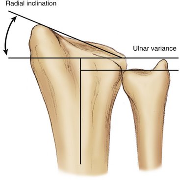
Ulnar variance is a parameter used in the context of distal radius fractures to help quantify the loss of radial length. Ulnar variance is determined by measuring the distance between two lines drawn perpendicular to a reference line extended along the axis of the radial shaft where one perpendicular intersects the distal edge of the ulnar head, and the second perpendicular intersects the CRP (see Fig. 3-10). Negative values indicate that the radius extends beyond the ulna; positive values indicate that the ulna extends beyond the radius. Ulnar variance is normally −0.6 mm with a standard deviation of 1 mm. Shortening of more than 5 mm is a relative indication for operative treatment.
Articular step-off is a parameter used with intra-articular fractures to measure discontinuity in height between two adjacent articular fragments.8 Generally, articular step-off of greater than 1 to 2 mm is considered a relative indication for operative treatment. Residual articular step-offs greater than these values have been associated with a high incidence of osteoarthritis in young patients. In addition, if significant depression between the scaphoid and lunate facet is seen on the PA view, the clinician should have a high index of suspicion for scapholunate injury.
Lateral View
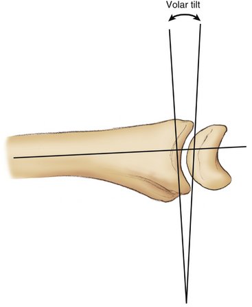
On the lateral view, volar tilt is used to measure the angular change of the articular surface. Volar tilt is defined as the angle between a line perpendicular to the central axis of the radial shaft and a line that connects the corner of the dorsal rim and the corner of the volar rim on the lateral view (Fig. 3-11). Normal wrists have about 10 degrees of volar tilt; dorsally angulated fractures with greater than 10 degrees of dorsal tilt are a relative indication for reduction. Fractures displaced to the volar side often show an increase in volar tilt. These fractures tend to be highly unstable and require some form of stabilization.
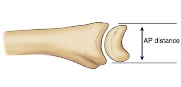
The AP distance is the point-to-point distance between the corner of the dorsal rim and the corner of the volar rim on the lateral view (Fig. 3-12). Normal AP distance measures 20 mm in men and 18 mm in women. Elevation of the AP distance more than 21 mm in men and 19 mm in women suggests discontinuity across the lunate facet with a separate dorsal and volar fragment. Marked widening of the AP interval may be the only evidence of sigmoid notch involvement that would be otherwise difficult to visualize on standard x-rays.9 It is usually better to measure the AP distance on the 10-degree lateral projection.
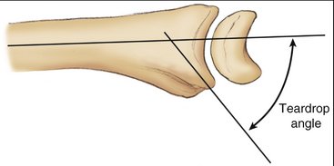
The teardrop angle is determined by measuring the angle between a line extended along the longitudinal axis of the radial shaft and a line that is drawn down the center of the teardrop; if the complete cortical outline of the teardrop is difficult to determine, a line drawn parallel to the subchondral bone of the volar rim can be used instead (Fig. 3-13). Depression of the teardrop angle below 45 degrees indicates significant dorsiflexion deformity of the volar rim of the lunate facet and should be corrected.
Fragmentation Patterns
Over the past 5 decades, many different classifications of distal radius fractures have been proposed, both as a suggestion for guidelines to treatment and as a predictor of the natural history of different patterns of injury. Traditional classifications of distal radius fractures were based on early descriptions of simple extra-articular fractures by Colles, Barton, and Smith.10 These initial observations described angulation of the distal fragment in a volar or dorsal direction. Further iterations of these descriptions incorporated the presence of comminution, involvement of the radial articular surface, displacement, direction of displacement and degree of articular surface involvement, length of the radial styloid, presence of dorsal angulation, and extent of metaphyseal comminution.11 Frykman12 identified the presence of radiocarpal joint, radioulnar joint, and ulnar styloid involvement. Later classification systems, such as the Melone13 and Mayo14 classifications, have underscored the importance of basic fragmentation patterns of the articular surface.
More recently, the AO15 and Fernandez/Jupiter16 classifications have proposed grouping patterns by the mechanism of injury. The AO system broadly divides fractures into bending, shear, and axial loading categories, with the Fernandez/Jupiter system adding carpal avulsions and high-energy trauma as additional categories. Although the AO classification divides patterns further into 27 subcategories, there is poor interobserver and intraobserver correlation beyond the three basic types.17–19
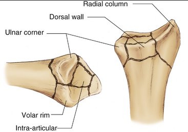
The fragment-specific classification system is based on the observation that fracture lines in distal radius fractures generally propagate along recurrent pathways, resulting in five basic fracture components: the radial column, ulnar corner, dorsal wall, volar rim, and free intra-articular fragments (Fig. 3-14). The radial column fragment is often a major fragment along the radial border of the wrist and is important to maintain radial length and provide support to the carpus across the radioscaphoid joint. The ulnar corner fragment involves the dorsal side of the lunate facet and the dorsal portion of the sigmoid notch, and typically migrates dorsally and proximally; significant displacement of this fragment can adversely affect movement and function of the DRUJ. Dorsal wall fragmentation is often a contributing factor in dorsal instability. The volar rim fragment is formed by the distal radial ridge and the volar portion of the lunate facet and is often a major element of fracture instability. This fragment can either displace volarly into the palmar soft tissue or impact axially, rotating into dorsiflexion with depression of the teardrop angle and dorsal subluxation of the carpus. Finally, free intra-articular fragments may displace and rotate into the metaphyseal cavity creating articular step-offs and joint incongruity.
Fractures of the distal ulna are usually classified based on the position of the fracture.20 Simple avulsions of the tip of the styloid are rarely clinically important, although they may be associated with more significant tears of the triangular fibrocartilaginous complex. Fractures through the base of the ulnar styloid may be associated with instability of the DRUJ, particularly if widely displaced with the carpus in a radial direction. Ulnar head fractures may involve the congruency of the articular surface of the DRUJ and cause dysfunction or late arthritis if left unreduced. Fractures through the neck or shaft of the ulna can compromise rotational stability of the forearm.
One contemporary approach to distal radius fractures is to combine the fragment-specific classification system with a characterization of fracture “personality,” which is based on mechanism, magnitude, and direction of injury.1 Because forces on the volar side of the radius are typically much higher than forces along the dorsal side, the direction of displacement of the distal fragment can significantly affect the characteristics and natural history of a particular fracture pattern. For this reason, extra-articular fractures with dorsal displacement from a dorsal bending mechanism are considered different from extra-articular fractures with volar displacement from a volar bending mechanism. Similarly, dorsal shear fractures have different characteristics in terms of prognosis and treatment from volar shear fractures. Finally, axial loading injuries may result in several different patterns based on the magnitude and direction of applied force (Table 3-1).
| Mechanism | Personality |
|---|---|
| Shear | Dorsal shear |
| Volar shear | |
| Bending | Dorsal bending |
| Volar bending | |
| Bending + axial | Three-part articular |
| Axial | Comminuted articular |
| Comminuted articular with volar rim dorsiflexion | |
| Comminuted articular with DRUJ instability |
DRUJ, distal radioulnar joint.
Dorsal bending injuries occur from a dorsal bending moment and result in compressive failure on the dorsal side and simple tensile failure on the volar cortex (Fig. 3-15). Characteristically, they manifest as a large single distal fragment that includes the articular surface of the radiocarpal joint and fragmentation of the dorsal wall along with compression of the metaphyseal cavity. In many cases, apposition of the volar cortex at a single fracture line between the proximal and distal fragment provides a stable fulcrum on which to hinge the reduction. In this situation, the amount of dorsal comminution and metaphyseal impaction is the primary determinant of the degree of dorsal instability. Although ligamentous damage to the DRUJ also may be present, often DRUJ stability is restored simply by reduction of the distal fragment.
In contrast to dorsal bending injuries, displaced volar bending injuries are nearly always unstable and are subject to an entirely different environment of deforming forces (Fig. 3-16). In this fracture personality, the distal fragment and carpus displace into the palmar soft tissues, and stable reduction across the volar cortex is often impossible with closed methods of management. Rotational deformities are difficult to assess radiographically. In contrast to dorsal bending injuries, in which the volar cortex can often be used as a fulcrum for balancing the dorsal instability pattern against the strong pull of the flexor tendons, the deforming pull of the flexor tendons in volar bending injuries results in palmar and proximal migration of the carpus and distal fragment. Volar bending injuries are characterized by volar subluxation of the rotational center of the base of the capitate in relation to the volar cortex of the shaft. In some cases, additional fragmentation of the volar wall also may be observed. In addition, displaced volar bending injuries show proximal carpal migration with loss of overall length and radial inclination. Volar tilt may be increased, and disruption of the DRUJ is commonly observed. Typically, these injuries require some type of operative intervention to achieve a stable reduction.
In volar shear fractures, the carpus is driven into the volar rim of the lunate facet, resulting in volar and proximal translation of this fragment (see Fig. 3-3). The carpus is carried by the volar rim fragment and dislocates off the remaining intact dorsal rim of the lunate facet. Volar and proximal migration of the teardrop occurs, and overlap of the dorsal rim and the carpus is seen on the PA view. As noted previously, discontinuity of the carpal facet horizon also may be noted on the PA view. On the lateral view, displacement of the carpus and volar rim is usually obvious, and increased AP distance is frequently noted. Particular focus should be on examination of the volar rim component for additional secondary fracture lines within the volar rim. Fragmentation into the radial column also may be present. In addition to injury views, postreduction x-rays should confirm that the center of rotation of the base of the capitate is restored to its normal relationship to a line extended from the volar cortex of the shaft, indicating that complete correction of volar subluxation of the carpus has been obtained. X-rays also should confirm that reduction has brought the volar rim back out to length, resulting in complete correction of the carpal facet horizon to its normal spatial alignment on the PA view.
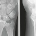
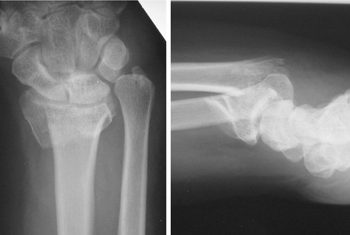
A pure dorsal shear fracture is a more uncommon pattern of injury. In this pattern, the impact of the carpus against the dorsal rim of the lunate facet results in a shear failure with varying degrees of dorsal subluxation and proximal migration of the carpus (Fig. 3-17). In dorsal shear fractures, significant articular step-offs are present in the sagittal plane, producing a sharp edge that can grind against the proximal pole of the lunate during flexion movements of the wrist. In volar shear fractures, the predominant clinical concern is correction of the significant volar instability of the carpus caused from the strong pull of the flexor tendons. In contrast, in dorsal shear fractures, the predominant clinical concern is the restoration of a smooth and congruous articular surface, eliminating deep articular offsets dorsally that may result in accelerated wear of the lunate during flexion movements of the wrist.
Simple three-part distal radius fractures consist of a proximal shaft fragment, an ulnar corner fragment, and a large distal articular fragment that contains the radial column and the volar rim (Fig. 3-18). Although this injury pattern is often described as the result of axial loading, it is probably the result of a combination of axial loading and simple bending mechanisms. The ulnar corner fragment often involves the dorsal portion of the sigmoid notch and usually includes the insertion of the dorsal ligament of the DRUJ. Three-part fractures usually show some loss of radial length and radial inclination on the PA view. On the lateral view, dorsal angulation of the distal fragment is frequently observed. Dorsal and sometimes proximal displacement of the ulnar corner fragment may occur. In addition, fragmentation of the dorsal wall is often seen.
Complex articular fractures tend to occur in two patterns, based on the direction and instability of the volar rim of the lunate facet. These complex axial load injuries can generate any or all of the five basic fracture components, resulting in significant step-offs or separations within the articular surface. In one pattern of injury, the impact of the carpus causes the articular surface to explode peripherally, resulting in displacement of the volar rim fragment volarly and proximally. In this pattern, volar or proximal migration of the carpus is observed. An independent radial column fragment is almost always present. In addition, free intra-articular fragments may be impacted into the metaphysis, and ulnar corner and dorsal wall fragments are commonly present (Fig. 3-19). Depressed radial inclination, widened AP interval, and incongruity of the articular surface are frequent radiographic findings with this injury. An inconsistent joint interval between the distal radius and proximal pole of the lunate on the lateral view can indicate articular disruption across the lunate facet. Dorsal or excessive volar tilt also may be present and depends on the principal direction of injury.
Comminuted articular fractures of the distal radius also may affect the ulna or DRUJ or both, which may complicate the injury pattern further (Fig. 3-20). Significant disruption of the DRUJ may occur with volar or dorsal subluxation of the distal ulna in relation to the distal radius. In some cases, excessive widening of the DRUJ may be noted. These fractures are usually associated with extreme comminution of the articular surface and malalignment of the carpus on the lateral view. Widening of the AP distance and a nonuniform joint interval on the lateral view are often features of this pattern. In addition to reconstruction of the articular surface, restoration of stability of the DRUJ is required and may include soft tissue reconstruction of the ligamentous structures.
Radial shear fractures are an unusual form of distal radius fractures. In radial shear fractures, translation of the carpus results in a shear fracture across the tip of the radial styloid, rather than the radial column type of injury seen with other fracture patterns. Radial translation of the carpus may be observed along with ulnar styloid injuries that have displaced toward the radius. In these fractures, the extent of articular surface damage is often underestimated by the radiographic findings, and supplemental arthroscopic evaluation may be required to assess fully the degree of joint damage. Marked widening of the DRUJ or bones of the forearm may implicate syndesmotic disruption; these injuries are particularly unstable in terms of DRUJ function (Fig. 3-21). In addition, particular attention should be directed toward assessing these injury patterns for additional intracarpal ligament pathology.
Carpal avulsions and high-energy trauma also have been included as forms of distal radius fractures, although these injuries have their own distinct features. Carpal avulsions are primarily ligamentous injuries to the carpus in which osseous fragments are avulsed from the radius. High-energy trauma injuries are associated with highly comminuted fractures of the distal articular surface of the radius along with extension well up into the shaft of the radius or ulna or both. Although these injuries may have an extensive osseous component, it is not unusual to have a substantial soft tissue component completely overshadow the clinical treatment of these fracture patterns.
Conclusion
In addition to an awareness of the essential radiographic landmarks and parameters, radiographic evaluation of distal radius fractures requires an understanding of the basic patterns of injuries to appreciate the anatomy of the injury and the mechanical basis of instability. Recognizing which fracture elements are present allows a mental picture of the injury to be developed. Categorizing the mechanism, direction, and magnitude of injury as one of several fracture personalities provides clinically useful information that relates to the source of instability and the possible modes of failure. With improved understanding of the structural anatomy and biomechanical basis of the injury, better treatment and clinical outcomes are likely to follow.
1. Medoff R. Essential radiographic evaluation for distal radius fractures. Hand Clin. 2005;21:279-288.
2. Boyer M, Korcek K, et al. Anatomic tilt x-rays of the distal radius: an ex vivo analysis of surgical fixation. J Hand Surg [Am]. 2004;29:116-122.
3. Pennock A, Phillips C, et al. The effects of forearm rotation on three wrist measurements: radial inclination, radial height and palmar tilt. Hand Surg. 2005;10:17-22.
4. Yeh G, Beredjiklian P, et al. Effects of forearm rotation on the clinical evaluation of ulnar variance. J Hand Surg [Am]. 2001;26:1042-1046.
5. Lundy D, Quisling S, et al. Tilted lateral radiographs in the evaluation of intra-articular distal radius fractures. J Hand Surg [Am]. 1999;24:249-256.
6. Mekhail A, Ebraheim N, et al. Anatomic and x-ray film studies of the distal articular surface of the radius. J Hand Surg [Am]. 1996;21:567-573.
7. Szabo R, Weber S. Comminuted intraarticular fractures of the distal radius. Clin Orthop. 1988;230:39-48.
8. McCallister W, Smith J, et al. A cadaver model to evaluate the accuracy and reproducibility of plain radiograph step and gap measurements for intra-articular fracture of the distal radius. J Hand Surg [Am]. 2004;29:841-847.
9. Rozental T, Bozentka D, et al. Evaluation of the sigmoid notch with computed tomography following intra-articular distal radius fracture. J Hand Surg [Am]. 2001;26:244-251.
10. Peltier L. Fractures of the distal end of the radius. Clin Orthop. 1984;187:18-22.
11. Gartland J, Werley C. Evaluation of healed Colles’ fractures. J Bone Joint Surg Am. 1951;33:895-907.
12. Frykman G. Fractures of the distal radius, including sequelae—shoulder and finger syndrome, disturbance in the distal radioulnar joint and impairment of nerve function: a clinical and experimental study. Acta Orthop Scand Suppl. 1967;108:1-153.
13. Melone CJ. Distal radius fractures: patterns of articular fragmentation. Orthop Clin North Am. 1993;24:239-253.
14. Cooney W. Fractures of the distal radius: a modern treatment-based classification. Orthop Clin North Am. 1993;24:211-216.
15. Muller M, Nazarian S, et al. The Comprehensive Classification of Fractures of Long Bones. Berlin: Springer-Verlag; 1990.
16. Jupiter J, Fernandez D. Comparative classification for fractures of the distal end of the radius. J Hand Surg [Am]. 1997;22:563-571.
17. Andersen DJ, Blair WF, et al. Classification of distal radius fractures: an analysis of interobserver reliability and intraobserver reproducibility. J Hand Surg [Am]. 1996;21:574-582.
18. Flinkkilä T, Nikkola-Sihto A, et al. Poor interobserver reliability of AO classification of fractures of the distal radius. J Bone Joint Surg Br. 1998;80:670-672.
19. Kreder H, Hanel D, et al. Consistency of AO fracture classification for the distal radius. J Bone Joint Surg Br. 1996;78:726-731.
20. Biyani A, Simison A, et al. Fractures of the distal radius and ulna. J Hand Surg [Br]. 1995;20:357-364.