69 Proton Therapy
Rapidly increasing interest in proton therapy is evident in the large attendance at proton therapy meetings and symposia, the growth of proton therapy vendors, and the growing involvement of major radiotherapy equipment manufacturers. At the time of writing (November 2009), there were seven hospital-based proton therapy centers operating in the United States (source http://ptcog.web.psi.ch). Many more are being built and planned around the world. In addition, at least two companies have entered the business of making small, single-room proton therapy facilities using compact accelerators.
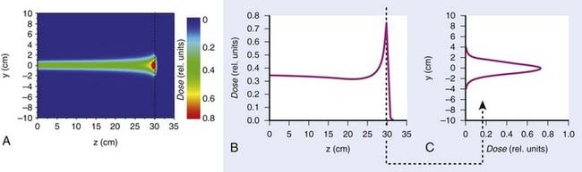
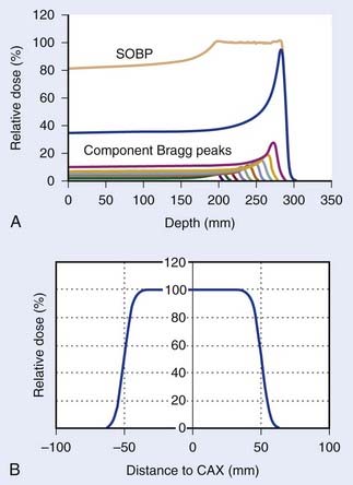
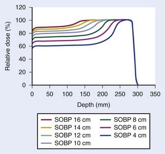
Such interest in protons (and, more generally, in heavier charged particles) is sparked by their energy deposition characteristics. Protons continuously interact as they traverse through a medium, losing energy along the way until they come to a stop. They deposit the greatest amount of energy per unit path-length near the end of their range. A characteristic depth–dose curve and beam profiles for a narrow monoenergetic beam of protons are shown in Fig. 69-1A. The peak of highest dose is called the Bragg peak. Dose distribution from such a beam would be of limited use in treating cancers of arbitrary shape and size. A therapeutically useful beam can be produced in two ways: (1) by appropriately modulating the energy of the initially narrow monoenergetic beam as well as scattering it laterally to cover a target volume of a given size, or (2) by scanning the narrow (pencil) beams of a sequence of energies magnetically. The former modality is called passively scattered proton therapy (PSPT). Fig. 69-2 shows a typical PSPT dose distribution in water, a distribution characterized by a lower dose at the entrance, a flat region called the spread-out Bragg peak (SOBP), and rapid fall-off at the distal edge. This figure also illustrates how a sequence of Bragg peaks of appropriate intensities adds to produce the SOBP. Such a dose distribution requires further custom shaping with a block or an aperture to conform the lateral dimensions of the beam to the shape of the target and a range compensator to conform the distal edge of the dose distribution to the distal edge of the target volume. In proton therapy with scanning beams, the intensities of thin proton “pencils” of a range of energies, terminating at a matrix of points in the target, are determined using optimization techniques to achieve specified clinical objectives. This is the proton therapy equivalent of intensity-modulated photon (radiation) therapy (IMRT, also called IMXT or intensity-modulated x-ray therapy) and is called intensity-modulated proton therapy (IMPT). Regardless of the modality, generally two or more fields are used per treatment fraction, though the number of fields for proton therapy is usually smaller than the number for photon therapy.
General Principles of Physics of Proton Therapy
Interactions of Protons With Matter
Nuclear interactions also result in the production of neutrons, an unwanted byproduct. Neutrons can travel large distances and necessitate the use of a large amount of shielding. They may also induce a significant level of radioactivity in the metallic objects they pass through and are of major concern because of their carcinogenic potential. Experts have cautioned about neutron contaminants when using passively scattered proton beams, especially for pediatric treatments.1–4 However, the designs of newer treatment delivery systems have substantially reduced neutron contaminants in the incident passively scattered beams. Of course, neutron contamination in the incident scanned beam is essentially zero. Neutrons generated in the patient are unaffected, but their number is relatively small.
Proton Accelerators
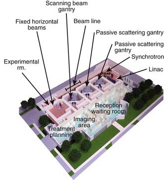
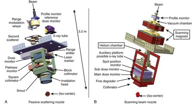
The narrow beam of protons produced by the accelerator has a relatively small initial energy and angular spread. After extraction from the accelerator, the beam is directed magnetically through the beam line to the gantry and into the treatment head or “nozzle.” The term nozzle is used in particle therapy to describe the treatment head that the beam passes through after leaving the evacuated beam line. Fig. 69-3 shows the treatment floor configuration at the M.D. Anderson Proton Center (MDACC) and Fig. 69-4 shows the schematics of the passive scattering and scanning beam nozzles of the Hitachi proton synchrotron, the accelerator at MDACC. Its important components are described in the figure caption.
Therapeutic Proton Beams
A beam of protons entering the nozzle is a focused, circularly symmetric thin pencil. As it traverses the air and monitoring devices, it spreads out slightly by the time it reaches the surface of the medium (patient, phantom, compensator, etc.). Once it enters the medium, the rate of interactions increases substantially. Typical dose distribution in water from such a beam is shown in Fig. 69-1. To be clinically useful, such distributions must be spread out laterally and longitudinally (i.e., in the direction of the beam). This can be achieved by either passively scattering protons with a combination of a rotating range modulation wheel (RMW) and a scattering foil or by varying the energy of the protons before they enter the nozzle and actively scanning with magnets.
Passively Scattered Proton Beans
Conventionally, proton dose distributions of therapeutic interest have been produced by passive scattering. In the technique most commonly employed, an RMW is used to produce protons of a sequence of energies up to a maximum. The RMW is like a propeller that is placed in the path of protons. It has multiple banks of steps of a range of thicknesses each. Fig. 69-5 shows the design of a Hitachi RMW. It has six banks of steps and rotates at 400 revolutions per minute, thus it modulates the initial beam’s energy 40 times per second. As the wheel rotates, the proton beam passes through different thickness of the material and is slowed down to different energies. Angular widths and thicknesses of the steps are designed so that the sum of the resulting individual Bragg peaks results in a flat, homogeneous depth dose distributions of the type shown in Figs. 69-2 and 69-6 and called the SOBP. The thinnest step corresponds to the deepest penetration and the thickest one corresponds to the most proximal Bragg peak desired. SOBPs of in-between widths may be achieved by turning the incident beam off and on repeatedly at predetermined angles during the wheel’s rotation.
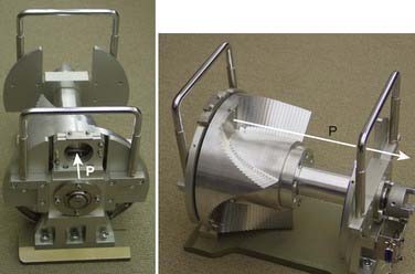
FIGURE 69-5 • Two views of a typical range-modulator wheel for the Hitachi proton therapy system. The wheel rotates at 400 rpm and modulates the incident beam six times per rotation, each modulation presents a series of steps to the monoenergetic proton beam producing a series of Bragg peaks. The angular width of each step is proportional to the intensity of the corresponding Bragg peak. These widths are chosen so that the sum of Bragg peaks is a spread-out Bragg peak (SOBP) of the type shown in Fig. 69-6. Turning the incident beam off and then on again on modulator steps less than the maximum thickness is used to produce SOBPs of different modulation widths. In combination with a second scatterer, the range-modulator wheel spreads the beam laterally to a size of predetermined diameter.
Scanned Beams
Magnetic scanning of thin pencil beams provides greater flexibility and control for creating optimum conformal proton dose distributions. In addition, the elimination of mechanical shaping devices (such as apertures and compensators) saves the time required for the insertion of these devices and eliminates the need to enter the treatment room between fields, thus, making treatments more efficient. Protons in a pencil beam incident on a patient or phantom are very nearly monoenergetic and are distributed essentially as a narrow Gaussian function of position relative to the pencil beam’s center. The lateral dimension of a pencil beam is expressed in terms of σ of the Gaussian or in terms of its full width at half-maximum (FWHM; 2.35 × σ). A smaller σ is desirable, because it allows for a sharper penumbra and greater control of dose distributions. In air, higher energy proton pencil beams have a smaller σ than the lower energy ones. Typically, the smallest achievable σ for the highest energies (220 to 250 MeV) ranges from 3 to 5 mm. Once the pencil beam enters a medium, such as a phantom or a patient, the σ increases substantially, especially near the end of the range of protons. This is illustrated in Fig. 69-1 for a Hitachi proton therapy system, which shows the dose distribution of a single pencil beam in water for a proton beam of range 21.5 cm (corresponding to an energy of 181.05 MeV). The FWHM of the pencil beam at the end of its range in water as a function of energy varies from approximately 12 mm for 220 MeV to 21 mm for 120 MeV.
The treatments with scanning beams are also referred to as spot scanning treatments. The lateral position of the spot is controlled by two orthogonal magnets, and the range of the spot is controlled by changing the energy of the incident pencil beams. The maximum depth of penetration of the pencils in tissue equivalent materials may vary from a few cm for the lowest energies to more than 36 cm for 250 MeV. Fig. 69-4B shows the Hitachi scanning beam nozzle. Field sizes of up to 30 cm × 30 cm can be achieved in this system.
Field Shaping
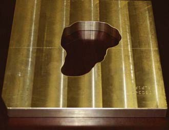
When a passively scattered beam is used to irradiate a water phantom, it produces a dose distribution with the depth dose characteristics depicted in Fig. 69-6 and an axially symmetric lateral distribution that tapers off gradually beyond the maximum radius of the intended flat region. To conform the dose distribution laterally to the shape of the target volume (plus appropriate margins), an aperture, typically made of brass of sufficient thickness (2 cm to 8 cm) to absorb incident protons of highest energy, is used (Fig. 69-7). Brass is a compromise material because it produces fewer neutrons than, say, lead or Cerrobend and yet the apertures are sufficiently compact and manageable. As illustrated in the schematic of the Hitachi passive scattering nozzle in Fig. 69-4A, the field aperture fits in a “snout,” a component at the end of the nozzle designed to hold field shaping devices. To achieve sharp beam boundaries, the field aperture is positioned close to the patient. However, the gap between the aperture and the patient reduces the intensity of the hot spots at shallow depths caused by protons scattered from the aperture. As mentioned above, the designers of the new proton therapy systems are considering multileaf collimators to shape the lateral field boundaries.
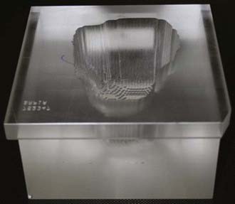
To create a dose distribution that conforms to the distal shape of the target, the SOBP of the passively scattered beam is shaped further by using a range compensator. A compensator is usually made of a nearly water-equivalent material such as Lucite (Fig. 69-8). It is designed to degrade the beam energy point-by-point by variable amounts so that the distal edge of the beam conforms to the shape of the target plus a suitable margin. The compensator is the final element in the nozzle. The air gap between the patient and the compensator is minimized to reduce the penumbra by moving the snout close to the patient. The aperture and compensator for each beam are designed by the planning system and the design information is used to fabricate these devices using computer-controlled milling machines.
Proton Treatment Planning
Because of these issues, the volumes and margins for targets and normal structures used in treatment planning, as described in International Comission on Radiological Units (ICRU) Reports 50 and 62,5,6 need to be reconsidered. The concept of planning target volume (PTV) has limitations even for conventional radiotherapy. For instance, assuming that the margins to extend clinical target volume (CTV) to PTV are chosen with appropriate consideration of inter- and intrafractional anatomic variations, the dose volume histogram (DVH) of a PTV represents the worst case scenario: clinical target volume is guaranteed to receive no less than the minimum dose to the PTV. It does not, however, reflect actual dose distribution received by the CTV, which may move around from time to time and from day to day within the PTV.
Treatment Planning Considerations for Passively Scattered Proton Therapy
Compensators designed simply to conform the distal edge of the proton dose distribution with the distal edge of the target assume that the patient’s anatomy is invariant over the course of radiotherapy and remains aligned with the compensator in day-to-day positioning. However, positioning uncertainties and changes in inhomogeneities relative to the target volume in the path of a proton beam would affect the depth of penetration and the conformity of the dose distribution to the distal and, to a lesser extent, proximal edge. To ensure coverage of the target in the presence of misalignment of the compensator with the anatomy and the variations of anatomic structures of significantly different densities, compensators are smeared.7 The smearing process essentially reduces the width of the higher thickness regions of the compensator to allow protons to penetrate more deeply even when adjacent higher density tissues move into their path. Smearing and margins for range uncertainty ensure coverage of the target, albeit at the expense of higher dose to normal tissues distal to the target. Furthermore, smearing would normally necessitate an increase in the modulation width to ensure that dose to the proximal edge is not compromised. Smearing also coincidentally reduces the consequences of inadequate accounting for lateral scatter in current proton planning systems.
Targets that move because of respiration present additional challenges for PSPT planning. It has been demonstrated that if proton planning for such targets is based on conventional CT images, the dose distributions seen on the treatment plan may be a poor representation of the dose distribution actually received by the patient, leading to target underdosing and normal-tissue overdosing.8 There have been recent attempts to incorporate respiration-induced motion into proton therapy planning. For example, four-dimensional (4D) CT data sets, comprising a sequence of three-dimensional (3D) CT data sets, one set for each phase of the respiratory cycle, may be used to design the motion-integrated internal target volume (ITV). The compensator design is then based on the so-called maximum intensity projection (or MIP) image of the ITV in which each voxel within the ITV is set to its maximum intensity in any one of the phases.8 An alternative approach reported by Engelsman et al.9 also uses the 4D CT. In it, one compensator is designed for each phase of the 4D CT. The union of all the compensators represents the final composite compensator. Either strategy ensures that protons will penetrate sufficiently deeply to cover the target adequately regardless of its position. However, actual dose distribution behind the target may be significantly higher compared with what would be seen on the resulting treatment plan. It is highly desirable that gated or breath-hold treatments be used for proton therapy if the intrafractional motion exceeds a certain threshold, e.g., 0.5 cm.
Treatment Plan Evaluation
At the next level, a relatively straightforward strategy for plan evaluation is a method recommended by Goitein et al.10–12 in the early 1980s and extended by Tony Lomax in the 1990s (private communication during Dr. Lomax’s visit to M.D. Anderson, February 13-16, 2006) and, more recently, by others, by incorporating respiratory motion (as presented by R. Mohan at the 44th meeting of the Particle Therapy Cooperative Group (PTCOG), Zurich, Switzerland, 2006). Multiple dose distributions for a given plan are computed for the nominal image and for each of the images obtained by plus and minus aterior-posterior (AP), lateral and superior inferior (SI) displacements of the body; plus and minus variations in CT numbers and, if applicable, end-inhale and end-exhale. A composite “worst case” dose distribution is then obtained by assigning to each voxel inside the CTV the minimum dose on any of the plans and to voxels outside the CTV the maximum dose on any of the plans. The resulting dose distributions and dose-volume histograms, representing the worst-case scenario, are then used to evaluate the plan. The computation of the large number of plans required for this approach is highly resource-intensive. Therefore, most often, in the current practice, the plan robustness is checked only against range uncertainty.
Dose Calculations for Proton Treatment Planning
To ensure that the dose received by the whole volume of the target is adequate and that normal tissues are not exposed to doses higher than their ability to tolerate, accurate knowledge of dose distributions is necessary as a part of the treatment planning process. These dose distributions are also used to predict the outcome of treatments and, in correlation with tumor control, toxicities and other outcomes for populations of patients, to establish dose-volume-response relationships. In the current state of the art, semiempirical pencil beam models are used for dose calculations for both passively scattered and intensity-modulated proton therapy.13–16 Lateral profiles are assumed to be Gaussian in shape. Lateral and depth dose parameters of the analytical formalisms of the model are fitted with measured dose distributions (sometimes a combination of two Gaussians). These models are quite accurate except for complex heterogeneities such as those in the head and neck or thoracic regions. For practical reasons, approximations are made, in particular with regard to accounting for scattering from inhomogeneities, surface irregularities, compensators and aperture boundaries. It may also be a challenge for these models to adequately account for devices in the path of the incident beam, such as monitor chambers, and for the effect of the magnetic field on the scanning beam that is only approximately monoenergetic. Model approximations could significantly affect the accuracy of dose distributions displayed on a treatment plan. Although there is a steady evolution of these models to improve accuracy, the ultimate solution is the use of Monte Carlo techniques. However, considering the computer-intensiveness of Monte Carlo, a hybrid of Monte Carlo and semiempirical methods may be a practical alternative for some applications such as IMPT optimization.
Biologic Properties
However, the biologic interactions of protons may be more complex than what has been assumed so far in clinical practice. Almost all of the experiments to date have been carried out in the middle of the SOBP of a flat homogeneous dose distribution. Furthermore, there is a substantial level of variability in the data. The LET of protons increases as they slow down, and therefore, the RBE increases with increasing depth.17,18 For example, it has been shown in animal experiments that the RBE at about 1 cm from the distal edge of the beam in an SOBP is about 1.2 compared to 1.1 (from presentation by J. Geuelette at the 45th meeting of PTCOG, Houston, 2006.). The LET distribution, and hence the RBE, in a passively scattered beam that has passed through a compensator and complex heterogeneities may be significantly different from 1.1 because of the spectral changes caused by scattering. Also, in IMPT, dose distributions in which the distal edge of each beam does not conform to the distal edge of the target and, instead, individual pencil beams meet inside the target volume, the LET and the RBE may be quite different from the values for the PSPT for the same physical dose distribution. It is also possible that the biologic interactions of protons with cells and tissues in the presence of chemotherapy or molecular agents are different compared to the corresponding interactions with photons.
Clinical Physics Issues
Proton therapy requires greater attention to the details of the treatment than does photon therapy.19 The limited range of the protons, which is their great advantage, is dependent upon all the objects through which the proton beam passes. These objects include any patient positioning devices, potentially the couch, the patient and the components of the nozzle including the beam monitors, compensator, and so on.
Simulation
This attention to details begins with patient simulation.20 Patient simulation is performed on a CT simulator with one or more well-defined imaging protocols. For protons, the CT Hounsfield units (HUs) must be converted to proton stopping power ratios. This conversion is established by the imaging of materials of known elemental composition to establish the relationship between their stopping powers and HUs and then entering the appropriate stopping power conversion factors (stopping power/HU) into the treatment planning system.21 These conversion factors may be a compromise to reflect the various imaging conditions, e.g., large CT field of view versus small CT field of view.
Treatment Planning
The proton treatment planning system (TPS) provides the treatment parameters, e.g., proton range, SOBP, gantry angle, couch position, etc.22 For passive scattering, the TPS may or may not provide the monitor units (MUs). For scanning beams, the TPS must provide the MUs per spot as well as the spot location and energy. The proton TPS not only generates the dose distribution but also the information required to construct the apertures and the compensators. Generally, only a limited number of beams are used for proton treatments, as acceptable treatment plans can be generated using two or three beams.
Patient-Specific Quality Assurance
Proton delivery systems require the determination of the number of MUs to deliver the prescribed dose. The dose prescription may be in units of biologically effective dose and may be converted to physical dose by the physics staff as part of the MU determination process. One approach to the determination of MUs for passively scattered beams is to use the patient dose distribution as input to calculate a “verification plan” in a water phantom. A representative point in the verification plan is chosen that corresponds to a point in the target volume where the dose is relatively uniform. Measurements can then be performed in a water phantom to determine the MUs required to deliver the prescribed dose. One significant parameter, which affects the number of MUs, is the SOBP factor: the smaller the SOBP, the more efficient the dose delivery, i.e., the fewer MUs required to deliver the dose. This factor can change by more than 50% as the SOBP width varies from 2 cm to 16 cm. It is possible to develop a simple manual dosimetry system to independently calculate the MUs required for a specific patient.23
Electronic Medical Record
The DICOM-RT* standard and its extension for particles, DICON-RT-ION, has helped in this information flow from the planning system to the delivery system.24 For protons, information also must flow to the machine shop so that apertures and compensators can be constructed. DICOM-RT-ION is an evolving standard that does not address all situations. An example of a weakness in the standard involves the fixed-beam room, i.e., the treatment room without a gantry. At MDACC, we have developed a software filter between the planning system and the delivery system for the fixed-beam room to account for the different interpretations of or noncompliance with the standard.
Machine Quality Assurance
Periodic (weekly, monthly quarterly, annual) safety and quality-assurance tests should be performed to insure proper operation of the proton delivery system. It is important to define these tests wisely, as there is limited beam time available for such tests and limited recommendations as to which specific tests should be performed. Maugham and Farr have recently provided their recommendations.25 It is possible to have an independent confirmation of the proton scattered and scanned beam calibrations in the same manner as for photon and electron beams, using thermoluminescence dosimetry (TLD) from the Radiological Physics Center (http://rpc.mdanderson.org).
Protons offer the potential of precise dose deposition with the subsequent sparing of normal tissue.26 High precision is only available if there is a high degree of attention to details. Failure to pay attention to these details may result in a poorer therapeutic outcome compared to photons, given the less forgiving nature of protons.
Proton Therapy of Head and Neck, Pediatric and CNS Cancers
In the laboratory, the effects of low-energy protons in human glioblastoma cells, compared to x-rays, were a higher RBE than 1.1 (the value normally used for clinical proton therapy), a lower repair capacity and a larger degree of G2 arrest.27 Another laboratory biology study on human fibrosarcoma cells after proton (or carbon ion) irradiation or photon irradiation showed decreased cell migration and invasion after particle therapy but the opposite after low doses of photon irradiation.28 If these observations are confirmed, they would be additional rationales for proton therapy.
Meningioma
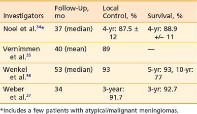
Approximately 90% to 95% of intracranial meningiomas are benign (WHO grade I), 5% are atypical (WHO grade II), and 3% are malignant (WHO grade III). The primary treatment is surgery. However if the resection is incomplete, recurrence rates of 55% at 10 years and 91% at 15 years have been reported.29 Radiation therapy after incomplete resection has been shown to decrease recurrence in retrospective reviews.30–33 Aggressive resection is generally not attempted for tumors at certain locations such as the cavernous sinus, petro-clival region, or sphenoid wing because of the associated morbidity. In these situations, primary radiation therapy has also been reported in retrospective reviews to produce good local control.30,32 Proton therapy to doses of 50 to 74 CGE has been used to treat recurrent or incompletely resected meningiomas. The 3- to 5-year control rates have been reported to be 80% to 100%.34–37 The result is summarized in Table 69-1. Late complication rates were found to be 10% to 25%. Currently, several institutions are testing hypofractionated proton therapy for benign meningiomas. For atypical and malignant meningiomas, one series reported 5- and 8-year control rates with radiation therapy of, respectively, 38% (atypical)/52% (malignant) and 19% (atypical)/17% (malignant). A nonrandomized comparison between proton therapy and photon therapy demonstrated a superior local control rate for proton therapy (80% versus 17% at 5 years; P = .003).38
Low-Grade Glioma
The first treatment for low-grade glioma is surgical resection whenever feasible. After a gross total resection, the patient can usually be observed without adjuvant therapy. For incomplete resection, a randomized trial has demonstrated that adjuvant radiation therapy could reduce the incidence of tumor recurrence but did not influence survival.39 However, if the tumor is not situated in an eloquent area where a recurrence could potentially cause significant neurologic deficit, postoperative radiation therapy could be postponed until there is evidence of recurrence. This approach is particularly relevant in children, because the delay in radiation therapy could postpone the potential effect of radiation on the development of the young brain. The use of conformal proton therapy has been reported in 27 children with progressive or recurrent low-grade astrocytomas.40 The radiation doses were from 50.4 to 63 CGE. After a mean follow-up period of 3.3 years, local control and survival rates were, respectively, 87% and 93% for central tumors, 71% and 86% for hemispheric tumors and 60% and 60% for brainstem tumors. All children whose tumors were controlled maintained their performance status. All children with optic pathway tumors experienced stable or improved vision. Moyamoya syndrome was diagnosed in one child with Type 1 neurofibromatosis. In adults, a small prospective phase I/II trial for patients with low-grade (Dausmas–Duport grade 2) and intermediate grade (Daumas–Guport grade 3) gliomas has been reported.41 This was a dose escalation trial in which grade 2 tumors received 68.2 CGE and grade 3 tumors received 79.7 CGE. The majority of patients did not have total resection. The 5-year survival for patients with grade 2 tumors was 71% and for those with grade 3 tumors was 23%. The major cause of death was tumor recurrence. Three of seven survivors had evidence of radiation necrosis. The authors did not find improvement in outcome for patients with grade 2 and 3 gliomas with these radiation doses and scheme. The result is not surprising in view of the results of two randomized trials using photon therapy on WHO grade II astrocytomas showing no statistical difference between 50.4 Gy and 64.8 Gy and between 45 Gy and 59.4 Gy.42,43
Glioblastoma
Currently, there is little justification to use proton therapy on patients with glioblastoma except in the context of a clinical trial with a well-defined rationale. A phase II trial to assess whether dose escalation to 90 CGE with conformal protons and photons in accelerated fractionation would improve the local control of glioblastoma and patient survival has been reported.44 In this study, the eligibility criteria included age between 18 and 70 years, Karnofsky performance status greater than or equal to 70, residual tumor volume of less than 60 ml and a unilateral, supratentorial location. The median survival was 20 months and 2- and 3-year survival rates were, respectively, 34% and 18%. The median survival appeared superior to that in comparable conventionally treated patients, but this is not a prospective randomized trial. Interestingly, most tumor recurrence occurred in areas that received doses of 60 to 70 CGE and only one patient developed recurrence in the 90-CGE volume. Several patients developed radiation necrosis without tumor recurrence, and their survival time was found to be longer than for those patients who developed tumor recurrence. Quality of life was not reported in this study.
Craniopharyngioma
Craniopharyngioma is curable with complete surgical excision. However, in many cases, the tumor can adhere densely to adjacent critical structures such as the optic nerve/chiasm and hypothalamus. This is particularly true for the adamantinomatous type of craniopharyngioma that more commonly occurs in children. In such situations, aggressive attempts at resection could cause significant morbidity. Several retrospective reviews have demonstrated equivalent cure rates after gross total resection and after radiation therapy following tumor cyst decompression and/or biopsy.45–47 In one series, the neurocognitive outcome was found to be better after radiation therapy than after surgery.48 Proton therapy has been used in a small number of patients and the 5- and 10-year local control rates have been reported to be 93% and 85%, respectively.49,50 About 20% of children were found to have learning difficulties but the functional status in adult patients was reported to be unaltered from the preradiotherapy status. Some patients developed new-onset panhypopituitarism. With strategic selection of proton beam directions, proton therapy has a distinct dosimetric advantage over photon therapy.51 Whether the advantage would result in improved functional outcome is a question for prospective clinical studies.
Pituitary Adenoma
Surgery, whether transphenoidal or via craniotomy, is the primary treatment for pituitary adenoma. If the tumor invades the cavernous sinus, has a large suprasellar extension adherent to the optic chiasm or the floor of the third ventricle, or significantly erodes the bony floor of the sella, there is a relatively high risk of residual microscopic or macroscopic disease after surgery and a resultant risk of tumor recurrence. Postoperative radiation therapy in doses of 45 to 50.4 Gy has produced a 10-year relapse-free survival rate of over 90%.52 This benign tumor is appropriately irradiated with a conformal technique (protons or photons). A small series using proton therapy has been reported.53 The follow-up period was relatively short. Forty-four out of forty-seven patients showed no tumor progression. The only morbidity was hypopituitarism, which may or may not be related to the proton therapy.
Medulloblastoma
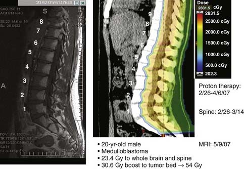
Craniospinal irradiation is the cornerstone of potentially curative therapy for most patients with medulloblastoma. Several dosimetric studies comparing protons and photons showed a clear advantage of proton therapy in its ability to reduce the radiation dose to the eyes, optic chiasm, hypothalamus-pituitary axis, cochleae, thyroid, lungs, heart, liver, and kidneys.54–56 The lack of exit dose with proton therapy is most evident in the treatment of the spine as part of craniospinal irradiation. Fig. 69-9 demonstrates the proton dose distribution within the vertebral bodies and the subsequent fatty change in the marrow corresponding to the proton dosimetry (a form of in vivo dosimetric verification). Another study estimated that proton therapy for medulloblastoma could reduce the risk of second malignancy by approximately ten-fold when compared to photon therapy.57 A cost-effectiveness evaluation also concluded that proton therapy could be cost effective and cost-saving when compared with conventional photon therapy in the treatment of children with medulloblastoma.58 The potential to significantly reduce late effects of craniospinal irradiation by protons has led to an increasing number of patients with medulloblastoma being treated with proton therapy. Prospective studies to evaluate and compare the late morbidity and quality of life in patients treated with proton therapy or photon therapy are underway.
Chordoma/Chondrosarcoma
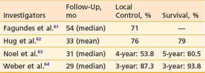
Chordoma and chondrosarcoma can occur at the base of skull or spine and usually present significant therapeutic challenges. Although surgery is an important modality of treatment, complete surgical resection of the tumor is not always possible. Radiation therapy has been used postoperatively for subtotally resected tumors as well as for recurrence after surgery. Conventional photon radiation techniques have not allowed high doses of radiation to be delivered safely and doses such as 50 to 55 Gy have produced local recurrence rates of 80% to 100%.59,60 In the past, higher doses (66 to 80 CGE) could be delivered only with conformal proton therapy and the reported results were better than those with photon therapy.61–64 For chondrosarcoma at the base of skull, the 3- and 5-year local control rates after proton therapy were, respectively, 91.6% to 94% and 75%. For chordoma at the base of skull, the 3- to 4-year local control rates after proton therapy were 53.8% to 87.3%, and the 3- to 5-year survival rates were 80.5% to 93.8% (Table 69-2). Proton therapy has also been used to treat chordoma and chondrosarcoma in pediatric patients with reported local control rates of 60% and 100%, respectively.65 Proposed prognostic factors include gender and residual tumor volume.60–62 These high doses of radiation deliverable with protons have been associated with significant complications such as cranial nerve injury and brain necrosis in 7% to 18% of patients.66,67 Currently, two prospective randomized studies compare 70 CGE with 78 CGE and 72 CGE with 80 CGE to test whether the higher doses could improve the rate of tumor control. In the spine, especially the sacrum, high doses of proton/photon-beam radiation therapy have also been used to treat chordoma either alone or combined with surgery.68 An interesting observation was that proton therapy was more effective when used postoperatively for the primary tumor than when used for recurrent chordomas. Local control by surgery and radiation was 12 out of 14 for primary tumors and one out of seven for recurrent tumors. Proton therapy alone with doses of 73 CGE or higher produced local control in three out of four patients. The tolerance of cauda equine has been shown to be different between men and women in this population of patients. The TD 5/5 and TD 50/5 were estimated to be, respectively, 55 CGE and 72 CGE for men and 67 CGE and 84 CGE for women.69
An experience using spot-scanning proton beam irradiation for spinal chordoma has been reported.70 The median dose used was 72 CGE and dose to the center of spinal cord was limited to 54 CGE. The 3-year overall survival and progression-free survival were 84% and 77%, respectively. The presence of metallic surgical implants was found to be associated with an increase in the rate of local failure. One reason could be that the implants caused “cold spots” in proton dose distributions in the tumor. Postoperative gross residual tumor above 30 ml was also negatively associated with overall survival and progression free survival. In this series, 4 out of 26 patients developed late adverse events.
Paranasal Sinus Tumors
Tumors in this region have a variety of histologies, including squamous cell carcinoma, carcinoma with neuroendocrine features, adenoid cystic carcinoma, adenocarcinoma, and sarcoma. They tend to present in a locally advanced stage and often involve the orbit and the base of skull, and therefore treatment can be challenging. Surgery is usually the first treatment, but adequate negative margins are difficult to achieve without significant morbidity. High doses of postoperative radiation therapy are frequently needed. Before the introduction of IMRT, high radiation doses could be satisfactorily delivered only with proton therapy. A dosimetric comparison between intensity modulated photon therapy and intensity modulated proton therapy showed comparable target dose conformation, but only protons could spare critical structures at all dose levels while simultaneously providing acceptable dose homogeneity within the target volume.71
The outcomes for 102 patients with locally advanced sinonasal cancers treated with a combination of protons and photons with or without surgery was recently reported.72 Patients who had complete surgical resection received a median dose of 67.6 Gy (range: 59.4 to 77.6 Gy); those who had partial resection or biopsy received median doses of 75.4 to 75.6 Gy (range: 55.4 to 79.4 Gy). Five-year local control rates were 82% to 95% irrespective of the extent of surgery. Complete resection was, however, associated with better disease-free survival and lower rate of distant metastasis than incomplete resection. The overall 5-year survival was worse for patients with squamous cell carcinoma (about 40%) than for patients with neuroendocrine tumors or adenoid cystic carcinoma (almost 70%). A separate analysis of visual outcome of a group of patients treated on an accelerated fractionation schedule demonstrated that 70 CGE could be delivered to the tumor with acceptable ophthalmologic complications (5-year probability of late effects of normal tissues [LENT]/common toxicity criteria [CTC] grade 2 or higher being 20.7% [±7.8]).73
Uveal Melanoma
To date, the largest number of patients treated with proton therapy has been those diagnosed with uveal melanoma. Dosimetric comparison with stereotactic photon therapy showed similar dose conformation, but lower doses to the ipsilateral lachrymal gland and total sparing of the contralateral eye as well as lower doses to the thyroid.74,75 The proton radiation doses used have been between 50 and 70 CGE, usually delivered in four fractions. A randomized trial testing 70 CGE versus 50 CGE did not show a significant difference in tumor control rates, rates of metastasis, or the overall complication rates,76 but the lower dose may be prudent for parapapillary and paramacular tumors to reduce complications. The 3- to 15-year local control rates and eye retention rates have been reported to be, respectively, 95% or higher and 84% to 92%.77–79 Even for large uveal melanomas (i.e., at least 10 mm maximum thickness or at least 20 mm maximum basal diameter), the 2-year local control rate was 67% and the 2-year metastasis-free survival was 90% and visual acuity 20/200 or better was achieved in 25% of the treated patients.80 Despite the high local control rate, death from metastasis could occur in over 50% patients with poor prognostic features. Liver is the most common site of metastasis. Reported prognostic factors include age, gender, tumor size, ciliary body involvement, retinal detachment, and local tumor recurrence.77–7981 Complications include rubeosis iridis, neovascular glaucoma, cataracts, and radiation vasculopathy (maculopathy and papillopathy). Cumulative 5-year rates of 64%, 35%, and 68%, respectively, for radiation maculopathy, radiation papillopathy, and vision loss have been reported.82 The complication rates appeared to be correlated with radiation dose to the macula and optic disc and enhanced by a history of diabetes. A second course of proton beam radiation therapy has been used in a small series of patients who developed recurrent uveal melanoma after an initial course of proton therapy.83 The doses of the second course ranged between 48 to 70 CGE. The 5-year local control rate and eye-retention rates were, respectively, 69% and 55%, and the 5-year metastasis-free survival was 73%. About a quarter of the reirradiated patients maintained useful vision.
Pediatric Sarcomas
A small series of pediatric patients with orbital rhabdomyosarcoma treated with PSPT has been reported.84 At a median follow-up of 6.3 years, six out of seven patients achieved local control. A dosimetric comparison against 3D conformal photon plans showed that protons were associated with lower doses to the brain, pituitary, hypothalamus, temporal lobes, and contralateral orbital structures. Another small series of children with rhabdomyosarcoma or other soft-tissue sarcomas treated with spot-scanning proton therapy has been reported.85 After a median follow-up of 18.6 months, 83.3% of children with rhabdomyosarcoma achieved local control, whereas 50% of those with nonrhabdomyosarcoma did so. As the number of proton therapy centers increases, more children with rhabdomyosarcoma or other sarcomas are being and will be treated with proton therapy, usually in combination with chemotherapy. More results will, hopefully, be available in a few years.
Proton Therapy for Thoracic, Abdominal, and Pelvic Cancers
Thoracic Tumors (Non–Small Cell Lung Cancer)
Although surgical resection may be the treatment of choice for early stage (i.e., stage I) NSCLC, many patients are deemed medically inoperable or refuse to undergo thoracotomy. Proton therapy affords an opportunity to treat these patients effectively with higher radiation doses in a hypofractionated manner. The physical properties of proton beams allow good dosimetric coverage, and the utilization of fewer entrance beams minimizes dose to normal lung tissue. This may be even more critical in patients who have poor baseline pulmonary reserve. Shioyama and colleagues published their clinical experience in treating 51 NSCLC patients with proton therapy (protons alone: 33; photons and protons: 19) at the University of Tsukuba.86 Twenty-eight of these patients had stage I disease and were treated to median doses of 70 Gray (Gy) (range: 60 to 81 Gy) for stage IA (n = 9) and 78 Gy (range: 60 to 93 Gy) for stage IB (n = 19). The median fraction size was 3 Gy (range: 2 to 6 Gy). Five-year local control rates were 89% and 39%, respectively, with 5-year overall survival rates of 70% and 16%, respectively. Only one patient experienced grade 3 toxicity, and no patients had grade 4 or higher toxicities.
This initial data led to a phase I/II trial of hypofractionated proton therapy in 21 stage I NSCLC patients (11 stage IA, 10 stage IB) by the same group.87 The first three patients received 50 Gy in 10 fractions and subsequent patients received 60 Gy in 10 fractions. The RBE was considered 1.0 for protons in this study (versus the more commonly used RBE of 1.1). With a median follow-up of 25 months, local progression-free rates for stage IA and IB patients were 100% and 90%, respectively. The 2-year overall and cause-specific survival rates were 74% and 86%, respectively. Two patients experienced late grade 2 toxicity, but no patient had grade 3 or higher toxicity.
In a similar phase II trial, investigators from Loma Linda University Medical Center treated 68 patients with stage I NSLC (29 T1, 39 T2) with hypofractionated proton therapy.88 The initial 22 patients received 51 CGE in 10 equal fractions and the subsequent 46 patients received 60 CGE in 10 fractions. In contrast to the Tsukuba study, the proton RBE in this study was considered to be 1.1. All patients had a minimum follow-up interval of 12 months with a median follow-up of 30 months. The 3-year local control rates were 87% for T1 tumors and 49% for T2 tumors, and the corresponding median survival durations were 39 and 19 months, respectively. Patients who received 60 CGE had significantly better 3-year overall survival rates than patients receiving 51 CGE (55% versus 27%, P = .03). No cases of pneumonitis or esophageal or cardiac toxicity were noted.
The clinical data on proton therapy for locally advanced lung cancer (stage III) is limited and often combines protons with photons. Comparative dosimetric studies suggest that proton therapy may have a benefit over photon therapy even if IMXT is used. Shioyama and colleagues published their small experience of treating eight stage III and 1 stage IV patients with proton therapy to gross tumor volume and photon therapy to the primary and elective regional lymph nodes without concurrent chemotherapy.86 The 2-year and 5-year overall survival rates were 62% and 0% and the corresponding cause-specific survivals were 70% and 0%, respectively.
In a prospective study, Bush and colleagues from Loma Linda reported their experience with eight stage IIIA NSCLC patients treated with combination photons (45 Gy in 1.8-Gy fractions) and protons (28.8 CGE in 1.8-CGE fractions delivered as concomitant boost with the last 16 photon treatments) to a total dose of 73.8 CGE.89 Concurrent chemotherapy was not routinely used. The 2-year overall survival and disease-free survival rates were 13% and 19%, respectively. The majority of the failures were distant (four of six) with only one in-field recurrence.
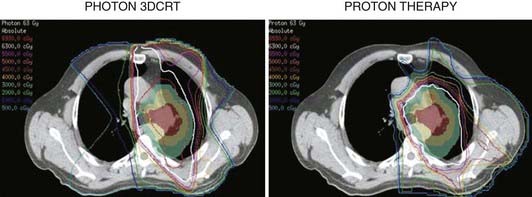
Although the early clinical experiences with proton therapy for locally advanced NSCLC were not impressive, one must consider that a significant portion of the radiation dose was given via photons, concurrent chemotherapy was not used, and 4D CT was not used for treatment planning. In a dosimetric comparative study, Chang and colleagues from MDACC showed significant reduction in dose to the normal lung, spinal cord, heart, and esophagus with the use of proton therapy compared to 3D photon therapy or IMXT (Fig. 69-10).90,91 These investigators purport that these dosimetric “savings” with proton therapy will allow further dose-escalation and concomitant use of chemotherapy in stage III NSCLC with fewer side effects. This has led them to initiate a prospective study of proton therapy with concurrent chemotherapy for stage III patients.
Abdominal Tumors (Liver Tumors)
The proton group at the University of Tsukuba reported their retrospective experience with proton therapy in 162 patients treated from 1985 to 1998.92 Several patients had multiple tumors treated (usually simultaneously) resulting in 192 total tumors irradiated. All the treatments were delivered using hypofractionated regimens (3.5 to 5 Gy) and total doses ranged between 50 Gy (10 fractions) to 84 Gy (24 fractions) with an RBE of 1.0. Two ports (lateral and anterior/posterior) were typically used, but other angles were used when necessary to avoid overdosing the gastrointestinal tract (Fig. 69-11). At a median follow-up interval of 31.7 months (range: 3.1 to 133.2 months), the 5-year local control rate was 86.9% and the corresponding overall survival rate was 23.5%. Survival appeared to be impacted by the level of liver dysfunction, with over 50% dying without tumor progression (e.g., liver cirrhosis). The acute side effects were limited primarily to elevation in liver enzymes (9.7%) and only five patients had grade 2 or higher late toxicity. Subsequent publications by this group have shown that proton therapy may be an effective modality for repeat treatments as well as for patients older than 80 years.93–95
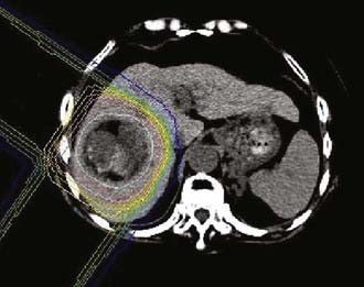
FIGURE 69-11 • Proton treatment plan for hepatocellular carcinoma (60 Gy in 10 fractions).
(From Hata M, Tokuuye K, Sugahara S, et al: Proton beam therapy for aged patients with hepatocellular carcinoma, Int J Radiat Oncol Biol Phys 2007.)
In a prospective phase II study, Bush and colleagues from Loma Linda treated 34 HCC patients with proton therapy to a total dose of 63 CGE in 4.2-CGE fractions (RBE = 1.1).96 This translates to a total dose of approximately 75 CGE in 2-CGE fractions. Beam angles were customized to the patient’s anatomy and tumor location but a two-beam arrangement (paired right posterior oblique ports) was most commonly used. All patients had a minimum follow-up period of 6 months and, at a median follow-up interval of 20 months, the 2-year local control rate was 75% and the overall survival rate was 55%. The treatments were well tolerated with few patients having signs of significant radiation-induced liver disease; however, six patients developed ascites after treatment.
Pelvis (Prostate)
The most common pelvic tumor treated to date with proton therapy has been prostate cancer. Proton therapy has offered a relatively straightforward treatment planning option for dose-escalation radiotherapy in this disease. One of the first randomized dose-escalation trials was performed using a proton boost. Shipley and colleagues conducted a randomized trial in 202 men with locally advanced prostate cancer (T3-4, N0-2), comparing 75.6 versus 67.2 CGE using 50.4 Gy delivered with four-field photons followed by either 25.5 CGE with protons (single perineal field) or 16.8 Gy via photons.97 Patients were treated from 1982 to 1992 (many in the pre–prostate-specific antigen [PSA] era) and no hormone therapy was given. With a median follow-up of 61 months (range: 3 to 139 months), there were no significant differences in overall, disease-specific, or recurrence-free survival. There was a trend toward improved local control in the higher dose arm with 5- and 8-year local control rates of 86% and 73%, respectively, versus 81% and 59%, respectively, in the conventional dose arm. Only patients with poorly differentiated tumors showed a statistically significant local control benefit on subset analysis (5-year rates of 94% versus 64%, respectively; P = .0014). The 8-year actuarial rectal toxicity rates were higher in the high dose arm (32% versus 12%; P = .002). However, the majority of men (31 of 34) with rectal bleeding were scored as RTOG grade 2 or less. Urinary toxicity rates were initially not significantly different, but a subsequent chart review of some of these patients suggested more persistent urinary issues in the high dose arm.98 The results of this study may not have applicability for modern proton therapy since these patients would likely receive combined hormonal and radiation therapy today, the majority of the dose was delivered via photons, and the perineal boost technique may not be optimal and has been largely abandoned. The last point may be especially true if one considers that the proton therapy was delivered with a split-course (1-week break) and a gold fiducial marker was placed in the apex. Depending upon the size of the marker, it may have resulted in dose shadowing at the target or inaccuracy in the CT numbers on the treatment planning scan because of metallic artifacts.99
The largest single institution experience in treating prostate cancer with proton therapy was published by Slater and colleagues from Loma Linda. They reported their retrospective experience using proton therapy (with and without combination photon therapy) in 1255 men with T1-3 prostate cancer treated from 1991 to 1997.100 Patients initially were treated with 30 CGE using opposed lateral proton beams to the prostate and seminal vesicles followed by 45 Gy to the first- and second-echelon pelvic lymph nodes using four-field photons. In later years, pelvic nodes were electively irradiated with photons on the basis of a >15% risk of lymph node involvement according to the Partin nomogram. Men with a <15% risk received proton therapy alone to the prostate and seminal vesicles to a dose of 74 CGE prescribed to isocenter. Proton treatments were performed with the assistance of a water-filled endorectal balloon, which helped minimize prostate motion and displaced the posterior and superior rectum away from the treatment fields. With a median follow-up interval of 62 months (range: 1 to 132 months), the 5-year and 8-year actuarial biochemical disease-free survival rates were 75% and 73%, respectively (using 1996 ASTRO consensus definition of three consecutive rises backdated). Significant independent predictors of biochemical outcome included pretreatment PSA, Gleason score, and posttreatment PSA nadir. Severe toxicity rates were low, with only 1.2% of patients experiencing late toxicities of RTOG grade 3 to 4. In a previous report with fewer patients and shorter follow-up, this group reported the 3-year late gastrointestinal and genitourinary RTOG grade 2 toxicity rates as 6% and 5%, respectively.101
These promising results led to a subsequent randomized dose-escalation trial comparing 70.2 versus 79.2 CGE (delivered at 1.8 CGE per fraction) in 393 men with T1b-2b prostate cancers with PSA <15 ng/mL between 1996 and 1999.102 All men received a combination of protons first (19.8 CGE versus 28.8 CGE) to the prostate with a 5-mm margin followed by 50.4 Gy with four-field photons to the prostate and seminal vesicles. With a median follow-up interval of 5.5 years (range: 1.2 to 8.2 years), there was a significant difference in 5-year biochemical control rates in favor of the high-dose arm (61.4% versus 80.4%; P < .001). This also was the first published dose-escalation study that showed a benefit to dose-escalation radiation for low-risk patients. The reader should be aware that the initial publication of this study in 2005 was flawed by an error in the statistical analysis of biochemical failure. Specifically, the original publication erroneously defined any three PSA rises as a failure rather than three consecutive rises.
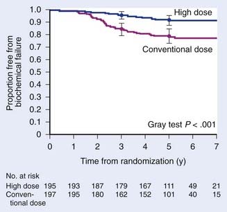
A subsequent reanalysis revealed that when the correct method for calculating the ASTRO-defined failure was used, the differences in PSA outcomes between the treatment arms remained significant (5-year biochemical control rates of 78.8% versus 91.3%; P < .001).103 Subset analysis showed a significant benefit to higher radiation doses for low risk patients with 5-year biochemical control rates of 82.6% versus 97.3% (P < .001) and intermediate risk patients (74.5% versus 87.4%; P = .02) (Fig. 69-12). Severe toxicity rates were low in either arm with grade 3 toxicity rates of only 3% and 2% in the conventional- and high-dose arms, respectively. Significantly more late grade 2 rectal toxicity was reported in the higher dose arm (17% versus 8% for the conventional dose arm; P = .005). However, these rates appear to be lower than seen in previously published dose-escalation trials with photons alone.104–106 Late grade 2 urinary toxicities were not significantly different between the two arms (18% to 20%). Preliminary data suggests that health-related quality of life between these two arms were also not significantly different.107 The favorable outcomes and tolerability with high-dose radiation using protons for a portion of the treatment has led to a phase I/II study investigating the tolerability and efficacy of 82 CGE (in 2-CGE fractions) for men with T1c-2b prostate cancers and PSA ≤15 ng/mL (American College of Radiology 0312).
Future improvements in proton therapy for these tumors will likely be founded on similar improvements for photon delivery. For example, the advent of 4D CT for treatment planning will improve target definition in tumors of the lung and liver. This is especially important for lung tumors since the relative tissue densities in the thorax vary greatly with a corresponding difference in radiologic path length. Improved knowledge and consistency of the radiologic path length in the proton beam path will result in better treatment plans.8,108 4D treatment planning may also be helpful in subsequent gating of proton therapy and has been used in the lung and liver by the group at Tsukuba.86,87,92,93
1 Hall EJ. Intensity-modulated radiation therapy, protons, and the risk of second cancers. Int J Radiat Oncol Biol Phys. 2006;65:1-7.
2 Hall EJ. The inaugural Frank Ellis Lecture—iatrogenic cancer: the impact of intensity-modulated radiotherapy. Clin Oncol (R Coll Radiol). 2006;18:277-282.
3 Hall EJ. The impact of protons on the incidence of second malignancies in radiotherapy. Technol Cancer Res Treat. 2007;6:31-34.
4 Brenner DJ, Hall EJ. Secondary neutrons in clinical proton radiotherapy: a charged issue. Radiother Oncol. 2008;86:165-170.
5 ICRU Report 62: Prescribing, recording and reporting photon beam therapy (supplement to ICRU report 50). Bethesda, MD: International Commission on Radiation Units and Measurements, 1999.
6 ICRU Report 50: Prescribing, recording, and reporting photon beam therapy. Bethesda, MD: International Commission on Radiation Units and Measurements, 1993.
7 Urie M, Goitein M, Wagner M. Compensating for heterogeneities in proton radiation therapy. Phys Med Biol. 1984;29:553-566.
8 Kang Y, Zhang X, Chang JY, et al. 4D proton treatment planning strategy for mobile lung tumors. Int J Radiat Oncol Biol Phys. 2007;67:906-914.
9 Engelsman M, Rietzel E, Kooy HM. Four-dimensional proton treatment planning for lung tumors. Int J Radiat Oncol Biol Phys. 2006;64:1589-1595.
10 Goitein M. Calculation of the uncertainty in the dose delivered during radiation therapy. Med Phys. 1985;12:608-612.
11 Goitein M, Abrams M. Multi-dimensional treatment planning: I. delineation of anatomy. Int J Radiat Oncol Biol Phys. 1983;9:777-787.
12 Goitein M, Abrams M, Rowell D, et al. Multi-dimensional treatment planning: II. beam’s eye-view, back projection, and projection through CT sections. Int J Radiat Oncol Biol Phys. 1983;9:789-797.
13 Schaffner B, Pedroni E, Lomax A. Dose calculation models for proton treatment planning using a dynamic beam delivery system: an attempt to include density heterogeneity effects in the analytical dose calculation. Phys Med Biol. 1999;44:27-41.
14 Schaffner B. Proton dose calculation based on in-air fluence measurements. Phys Med Biol. 2008;53:1545-1562.
15 Gottschalk B, Koehler AM, Schneider RJ, et al. Multiple coulomb scattering of 160 mev protons. nuclear instruments & methods in physics research section B-Beam Interactions with Materials and Atoms. 1993;74:467-490.
16 Hong L, Goitein M, Bucciolini M, et al. A pencil beam algorithm for proton dose calculations. Phys Med Biol. 1996;41:1305-1330.
17 Paganetti H. Significance and implementation of RBE variations in proton beam therapy. Technol Cancer Res Treat. 2003;2:413-426.
18 Paganetti H, Niemierko A, Ancukiewicz M, et al. Relative biological effectiveness (RBE) values for proton beam therapy. Int J Radiat Oncol Biol Phys. 2002;53:407-421.
19 Schulte RW. Proton treatment room concepts for precision and efficiency. Technol Cancer Res Treat. 2007;6:55-60.
20 Engelsman M, Mazal A, Jaffray D. Patient positioing and set-up verification for planning and treatments. In: Delaney T, Kooy H, editors. Proton and charged particle radiotherapy. Philadelphia, PA: Lippincott, Williams & Wilkins, 2008.
21 Schaffner B, Pedroni E. The precision of proton range calculations in proton radiotherapy treatment planning: experimental verification of the relation between CT-HU and proton stopping power. Phys Med Biol. 1998;43:1579-1592.
22 Bussiere MR, Adams JA. Treatment planning for conformal proton radiation therapy. Technol Cancer Res Treat. 2003;2:389-399.
23 Kooy HM, Schaefer M, Rosenthal S, et al. Monitor unit calculations for range-modulated spread-out Bragg peak fields. Phys Med Biol. 2003;48:2797-2808.
24 Liu BJ. A knowledge-based imaging informatics approach for managing proton beam therapy of cancer patients. Technol Cancer Res Treat. 2007;6:77-84.
25 Maugham RL, Farr JB. Quality assurance for proton therapy. In: Delaney T, Kooy H, editors. Proton and charged particle radiotherapy. Philadelphia: Lippincott, Williams & Wilkins, 2008.
26 Suit H, Goldberg S, Niemierko A, et al. Proton beams to replace photon beams in radical dose treatments. Acta Oncol. 2003;42:800-808.
27 Moertel H, Georgi JC, Distel L, et al. Effects of low energy protons on clonogenic survival, DSB repair and cell cycle in human glioblastoma cells and B14 fibroblasts. Radiother Oncol. 2004;73(Suppl 2):S115-118.
28 Ogata T, Teshima T, Kagawa K, et al. Particle irradiation suppresses metastatic potential of cancer cells. Cancer Res. 2005;65:113-120.
29 Mirimanoff RO, Dosoretz DE, Linggood RM, et al. Meningioma: analysis of recurrence and progression following neurosurgical resection. J Neurosurg. 1985;62:18-24.
30 Goldsmith BJ, Wara WM, Wilson CB, et al. Postoperative irradiation for subtotally resected meningiomas. A retrospective analysis of 140 patients treated from 1967 to 1990. J Neurosurg. 1994;80:195-201.
31 Nutting C, Brada M, Brazil L, et al. Radiotherapy in the treatment of benign meningioma of the skull base. J Neurosurg. 1999;90:823-827.
32 Pourel N, Auque J, Bracard S, et al. Efficacy of external fractionated radiation therapy in the treatment of meningiomas: a 20-year experience. Radiother Oncol. 2001;61:65-70.
33 Uy NW, Woo SY, Teh BS, et al. Intensity-modulated radiation therapy (IMRT) for meningioma. Int J Radiat Oncol Biol Phys. 2002;53:1265-1270.
34 Noel G, Habrand JL, Mammar H, et al. Highly conformal therapy using proton component in the management of meningiomas. Preliminary experience of the Centre de Protontherapie d’Orsay. Strahlenther Onkol. 2002;178:480-485.
35 Vernimmen FJ, Harris JK, Wilson JA, et al. Stereotactic proton beam therapy of skull base meningiomas. Int J Radiat Oncol Biol Phys. 2001;49:99-105.
36 Wenkel E, Thornton AF, Finkelstein D, et al. Benign meningioma: partially resected, biopsied, and recurrent intracranial tumors treated with combined proton and photon radiotherapy. Int J Radiat Oncol Biol Phys. 2000;48:1363-1370.
37 Weber DC, Lomax AJ, Rutz HP, et al. Spot-scanning proton radiation therapy for recurrent, residual or untreated intracranial meningiomas. Radiother Oncol. 2004;71:251-258.
38 Hug EB, Devries A, Thornton AF, et al. Management of atypical and malignant meningiomas: role of high-dose, 3D-conformal radiation therapy. J Neurooncol. 2000;48:151-160.
39 Karim AB, Afra D, Cornu P, et al. Randomized trial on the efficacy of radiotherapy for cerebral low-grade glioma in the adult: European Organization for Research and Treatment of Cancer Study 22845 with the Medical Research Council study BRO4: an interim analysis. Int J Radiat Oncol Biol Phys. 2002;52:316-324.
40 Hug EB, Muenter MW, Archambeau JO, et al. Conformal proton radiation therapy for pediatric low-grade astrocytomas. Strahlenther Onkol. 2002;178:10-17.
41 Fitzek MM, Thornton AF, Harsh Gt, et al. Dose-escalation with proton/photon irradiation for Daumas-Duport lower-grade glioma: results of an institutional phase I/II trial. Int J Radiat Oncol Biol Phys. 2001;51:131-137.
42 Shaw E, Arusell R, Scheithauer B, et al. Prospective randomized trial of low- versus high-dose radiation therapy in adults with supratentorial low-grade glioma: initial report of a North Central Cancer Treatment Group/Radiation Therapy Oncology Group/Eastern Cooperative Oncology Group study. J Clin Oncol. 2002;20:2267-2276.
43 Karim AB, Maat B, Hatlevoll R, et al. A randomized trial on dose-response in radiation therapy of low-grade cerebral glioma: European Organization for Research and Treatment of Cancer (EORTC) Study 22844. Int J Radiat Oncol Biol Phys. 1996;36:549-556.
44 Fitzek MM, Thornton AF, Rabinov JD, et al. Accelerated fractionated proton/photon irradiation to 90 cobalt gray equivalent for glioblastoma multiforme: results of a phase II prospective trial. J Neurosurg. 1999;91:251-260.
45 Weiss M, Sutton L, Marcial V, et al. The role of radiation therapy in the management of childhood craniopharyngioma. Int J Radiat Oncol Biol Phys. 1989;17:1313-1321.
46 Minniti G, Saran F, Traish D, et al. Fractionated stereotactic conformal radiotherapy following conservative surgery in the control of craniopharyngiomas. Radiother Oncol. 2007;82:90-95.
47 Combs SE, Thilmann C, Huber PE, et al. Achievement of long-term local control in patients with craniopharyngiomas using high precision stereotactic radiotherapy. Cancer. 2007;109:2308-2314.
48 Merchant TE, Kiehna EN, Kun LE, et al. Phase II trial of conformal radiation therapy for pediatric patients with craniopharyngioma and correlation of surgical factors and radiation dosimetry with change in cognitive function. J Neurosurg. 2006;104:94-102.
49 Luu QT, Loredo LN, Archambeau JO, et al. Fractionated proton radiation treatment for pediatric craniopharyngioma: preliminary report. Cancer J. 2006;12:155-159.
50 Fitzek MM, Linggood RM, Adams J, et al. Combined proton and photon irradiation for craniopharyngioma: long-term results of the early cohort of patients treated at Harvard Cyclotron Laboratory and Massachusetts General Hospital. Int J Radiat Oncol Biol Phys. 2006;64:1348-1354.
51 Bolsi A, Fogliata A, Cozzi L. Radiotherapy of small intracranial tumours with different advanced techniques using photon and proton beams: a treatment planning study. Radiother Oncol. 2003;68:1-14.
52 Brada M, Rajan B, Traish D, et al. The long-term efficacy of conservative surgery and radiotherapy in the control of pituitary adenomas. Clin Endocrinol (Oxf). 1993;38:571-578.
53 Ronson BB, Schulte RW, Han KP, et al. Fractionated proton beam irradiation of pituitary adenomas. Int J Radiat Oncol Biol Phys. 2006;64:425-434.
54 St Clair WH, Adams JA, Bues M, et al. Advantage of protons compared to conventional x-ray or IMRT in the treatment of a pediatric patient with medulloblastoma. Int J Radiat Oncol Biol Phys. 2004;58:727-734.
55 Lee CT, Bilton SD, Famiglietti RM, et al. Treatment planning with protons for pediatric retinoblastoma, medulloblastoma, and pelvic sarcoma: how do protons compare with other conformal techniques? Int J Radiat Oncol Biol Phys. 2005;63:362-372.
56 Timmermann B, Lomax AJ, Nobile L, et al. Novel technique of craniospinal axis proton therapy with the spot-scanning system: avoidance of patching multiple fields and optimized ventral dose distribution. Strahlenther Onkol. 2007;183:685-688.
57 Miralbell R, Lomax A, Cella L, et al. Potential reduction of the incidence of radiation-induced second cancers by using proton beams in the treatment of pediatric tumors. Int J Radiat Oncol Biol Phys. 2002;54:824-829.
58 Lundkvist J, Ekman M, Ericsson SR, et al. Cost-effectiveness of proton radiation in the treatment of childhood medulloblastoma. Cancer. 2005;103:793-801.
59 Catton C, O’Sullivan B, Bell R, et al. Chordoma: long-term follow-up after radical photon irradiation. Radiother Oncol. 1996;41:67-72.
60 Colli B, Al-Mefty O. Chordomas of the craniocervical junction: follow-up review and prognostic factors. J Neurosurg. 2001;95:933-943.
61 Fagundes MA, Hug EB, Liebsch NJ, et al. Radiation therapy for chordomas of the base of skull and cervical spine: patterns of failure and outcome after relapse. Int J Radiat Oncol Biol Phys. 1995;33:579-584.
62 Hug EB, Loredo LN, Slater JD, et al. Proton radiation therapy for chordomas and chondrosarcomas of the skull base. J Neurosurg. 1999;91:432-439.
63 Noel G, Feuvret L, Calugaru V, et al. Chordomas of the base of the skull and upper cervical spine. One hundred patients irradiated by a 3D conformal technique combining photon and proton beams. Acta Oncol. 2005;44:700-708.
64 Weber DC, Rutz HP, Pedroni ES, et al. Results of spot-scanning proton radiation therapy for chordoma and chondrosarcoma of the skull base: the Paul Scherrer Institut experience. Int J Radiat Oncol Biol Phys. 2005;63:401-409.
65 Hug EB, Sweeney RA, Nurre PM, et al. Proton radiotherapy in management of pediatric base of skull tumors. Int J Radiat Oncol Biol Phys. 2002;52:1017-1024.
66 Santoni R, Liebsch N, Finkelstein DM, et al. Temporal lobe (TL) damage following surgery and high-dose photon and proton irradiation in 96 patients affected by chordomas and chondrosarcomas of the base of the skull. Int J Radiat Oncol Biol Phys. 1998;41:59-68.
67 Pai HH, Thornton A, Katznelson L, et al. Hypothalamic/pituitary function following high-dose conformal radiotherapy to the base of skull: demonstration of a dose-effect relationship using dose-volume histogram analysis. Int J Radiat Oncol Biol Phys. 2001;49:1079-1092.
68 Park L, Delaney TF, Liebsch NJ, et al. Sacral chordomas: impact of high-dose proton/photon-beam radiation therapy combined with or without surgery for primary versus recurrent tumor. Int J Radiat Oncol Biol Phys. 2006;65:1514-1521.
69 Pieters RS, Niemierko A, Fullerton BC, et al. Cauda equina tolerance to high-dose fractionated irradiation. Int J Radiat Oncol Biol Phys. 2006;64:251-257.
70 Rutz HP, Weber DC, Sugahara S, et al. Extracranial chordoma: outcome in patients treated with function-preserving surgery followed by spot-scanning proton beam irradiation. Int J Radiat Oncol Biol Phys. 2007;67:512-520.
71 Lomax AJ, Goitein M, Adams J. Intensity modulation in radiotherapy: photons versus protons in the paranasal sinus. Radiother Oncol. 2003;66:11-18.
72 Resto VA, Chan AW, Deschler DG, et al. Extent of surgery in the management of locally advanced sinonasal malignancies. Head Neck. 2008;30:222-229.
73 Weber DC, Chan AW, Lessell S, et al. Visual outcome of accelerated fractionated radiation for advanced sinonasal malignancies employing photons/protons. Radiother Oncol. 2006;81:243-249.
74 Weber DC, Bogner J, Verwey J, et al. Proton beam radiotherapy versus fractionated stereotactic radiotherapy for uveal melanomas: a comparative study. Int J Radiat Oncol Biol Phys. 2005;63:373-384.
75 Zytkovicz A, Daftari I, Phillips TL, et al. Peripheral dose in ocular treatments with cyberknife and gamma knife radiosurgery compared to proton radiotherapy. Phys Med Biol. 2007;52:5957-5971.
76 Gragoudas ES, Lane AM, Regan S, et al. A randomized controlled trial of varying radiation doses in the treatment of choroidal melanoma. Arch Ophthalmol. 2000;118:773-778.
77 Gragoudas E, Li W, Goitein M, et al. Evidence-based estimates of outcome in patients irradiated for intraocular melanoma. Arch Ophthalmol. 2002;120:1665-1671.
78 Dendale R, Lumbroso-Le Rouic L, Noel G, et al. Proton beam radiotherapy for uveal melanoma: results of Curie Institut-Orsay proton therapy center (ICPO). Int J Radiat Oncol Biol Phys. 2006;65:780-787.
79 Hocht S, Bechrakis NE, Nausner M, et al. Proton therapy of uveal melanomas in Berlin. 5 years of experience at the Hahn-Meitner Institute. Strahlenther Onkol. 2004;180:419-424.
80 Kodjikian L, Roy P, Rouberol F, et al. Survival after proton-beam irradiation of uveal melanomas. Am J Ophthalmol. 2004;137:1002-1010.
81 Conway RM, Poothullil AM, Daftari IK, et al. Estimates of ocular and visual retention following treatment of extra-large uveal melanomas by proton beam radiotherapy. Arch Ophthalmol. 2006;124:838-843.
82 Gragoudas ES, Li W, Lane AM, et al. Risk factors for radiation maculopathy and papillopathy after intraocular irradiation. Ophthalmology. 1999;106:1571-1577.
83 Marucci L, Lane AM, Li W, et al. Conservation treatment of the eye: conformal proton reirradiation for recurrent uveal melanoma. Int J Radiat Oncol Biol Phys. 2006;64:1018-1022.
84 Yock T, Schneider R, Friedmann A, et al. Proton radiotherapy for orbital rhabdomyosarcoma: clinical outcome and a dosimetric comparison with photons. Int J Radiat Oncol Biol Phys. 2005;63:1161-1168.
85 Timmermann B, Schuck A, Niggli F, et al. Spot-scanning proton therapy for malignant soft tissue tumors in childhood: first experiences at the Paul Scherrer Institute. Int J Radiat Oncol Biol Phys. 2007;67:497-504.
86 Shioyama Y, Tokuuye K, Okumura T, et al. Clinical evaluation of proton radiotherapy for non–small cell lung cancer. Int J Radiat Oncol Biol Phys. 2003;56:7-13.
87 Hata M, Tokuuye K, Kagei K, et al. Hypofractionated high-dose proton beam therapy for Stage I non–small cell lung cancer: preliminary results of a phase I/II clinical study. Int J Radiat Oncol Biol Phys. 2007.
88 Bush DA, Slater JD, Shin BB, et al. Hypofractionated proton beam radiotherapy for stage I lung cancer. Chest. 2004;126:1198-1203.
89 Bush DA, Slater JD, Bonnet R, et al. Proton-beam radiotherapy for early-stage lung cancer. Chest. 1999;116:1313-1319.
90 Chang JY, Liu HH, Komaki R. Intensity modulated radiation therapy and proton radiotherapy for non–small cell lung cancer. Curr Oncol Rep. 2005;7:255-259.
91 Chang JY, Zhang X, Wang X, et al. Significant reduction of normal tissue dose by proton radiotherapy compared with three-dimensional conformal or intensity-modulated radiation therapy in stage I or stage III non–small cell lung cancer. Int J Radiat Oncol Biol Phys. 2006;65:1087-1096.
92 Chiba T, Tokuuye K, Matsuzaki Y, et al. Proton beam therapy for hepatocellular carcinoma: a retrospective review of 162 patients. Clin Cancer Res. 2005;11:3799-3805.
93 Hashimoto T, Tokuuye K, Fukumitsu N, et al. Repeated proton beam therapy for hepatocellular carcinoma. Int J Radiat Oncol Biol Phys. 2006;65:196-202.
94 Hata M, Tokuuye K, Sugahara S, et al. Proton beam therapy for hepatocellular carcinoma with limited treatment options. Cancer. 2006;107:591-598.
95 Hata M, Tokuuye K, Sugahara S, et al. Proton beam therapy for aged patients with hepatocellular carcinoma. Int J Radiat Oncol Biol Phys. 2007.
96 Bush DA, Hillebrand DJ, Slater JM, et al. High-dose proton beam radiotherapy of hepatocellular carcinoma: preliminary results of a phase II trial. Gastroenterology. 2004;127:S189-193.
97 Shipley WU, Verhey LJ, Munzenrider JE, et al. Advanced prostate cancer: the results of a randomized comparative trial of high dose irradiation boosting with conformal protons compared with conventional dose irradiation using photons alone. Int J Radiat Oncol Biol Phys. 1995;32:3-12.
98 Gardner BG, Zietman AL, Shipley WU, et al. Late normal tissue sequelae in the second decade after high dose radiation therapy with combined photons and conformal protons for locally advanced prostate cancer. J Urology. 2002;167:123-126.
99 Newhauser W, Fontenot J, Koch N, et al. Monte Carlo simulations of the dosimetric impact of radiopaque fiducial markers for proton radiotherapy of the prostate. Phys Med Biol. 2007;52:2937-2952.
100 Slater JD, Rossi CJJr, Yonemoto LT, et al. Proton therapy for prostate cancer: the initial Loma Linda University experience. Int J Radiat Oncol Biol Phys. 2004;59:348-352.
101 Slater JD, Rossi CJJr, Yonemoto LT, et al. Conformal proton therapy for early-stage prostate cancer. Urology. 1999;53:978-984.
102 Zietman AL, DeSilvio ML, Slater JD, et al. Comparison of conventional-dose vs high-dose conformal radiation therapy in clinically localized adenocarcinoma of the prostate: a randomized controlled trial. JAMA. 2005;294:1233-1239.
103 Zietman AL. Correction: inaccurate analysis and results in a study of radiation therapy in adenocarcinoma of the prostate. Jama. 2008;299:898-899.
104 Kuban DA, Tucker SL, Dong L, et al. Long-term results of the M.D. Anderson randomized dose-escalation trial for prostate cancer. Int J Radiat Oncol Biol Phys. 2008;70:67-74.
105 Peeters ST, Heemsbergen WD, van Putten WL, et al. Acute and late complications after radiotherapy for prostate cancer: results of a multicenter randomized trial comparing 68 Gy to 78 Gy. Int J Radiat Oncol Biol Phys. 2005;61:1019-1034.
106 Pollack A, Zagars GK, Starkschall G, et al. Prostate cancer radiation dose response: results of the M.D. Anderson phase III randomized trial. Int J Radiat Oncol Biol Phys. 2002;53:1097-1105.
107 Talcott JA, Slater JD, Zietman AL. Long-term quality of life after conventional-dose versus high-dose radiation for prostate cancer: results from a randomized trial (PROG-9509). J Clin Oncol. 2008;26(15S):264S.
108 Hui Z, Zhang X, Starkschall G, et al. Effects of interfractional motion and anatomic changes on proton therapy dose distribution in lung cancer. Int J Radiat Oncol Biol Phys. 2008.