[level-membership-for-cardiovascular-category]
CHAPTER 20 Physics and Instrumentation of Cardiac Single Photon Emission Computed Tomography
Successful performance and interpretation of cardiac single photon emission computed tomography (SPECT) studies relies on a basic understanding of the physics and instrumentation that allows for the generation of the images. The first practical system for the in vivo imaging of radionuclides was developed in the late 1950s by Anger and became commercially available in 1962.1 Despite more than 45 years of use and technical advances, the basic physics and design principles used today for cardiac SPECT imaging are remarkably similar to Anger’s initial concept.
PHYSICS AND SPECT IMAGING
Basic Atomic Structure
The classically described structure of an atom is known as the Bohr atom. It depicts a set of electrons orbiting the nucleus in stable electron shells (K, L, M, N) (Fig. 20-1). Each of the shells represents an energy state, with the innermost shell (K) associated with the greatest potential energy. Each electron’s energy state is defined further by a discrete set of four quantum numbers per electron. The Pauli exclusion principle states that no two electrons in the same atom can have an identical set of quantum numbers. By definition, a stable atom exists in its lowest possible energy state. When the energy state of an electron is increased (i.e., moved to a higher energy orbital shell or via absorption of external energy), the electron emits energy spontaneously as it returns to its lower, more stable energy state. This emission of energy by unstable electrons provides one mechanism for radionuclide imaging and is described in detail in the next section.
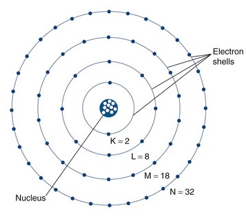
 FIGURE 20-1
Electrons orbit a nucleus composed of a dense conglomerate of protons and neutrons that are bound together by a network of so-called strong nuclear forces. A proton contains a charge of 1.6 × 10⁻¹⁹ coulombs, which is the exact opposite charge of an electron. Neutrons are particles of slightly greater mass than protons, but are uncharged. The number of protons present in its nucleus, or Z number, defines each element, whereas the mass number, or A, represents the number of protons plus the number of neutrons. Specific nomenclature defines the relationship between the number of protons and neutrons in a nucleus (Table 20-1). The ratio of protons to neutrons defines the stability of a particular nucleus (Fig. 20-2); the transformation of an unstable nucleus to a more stable state is responsible for many of the radioactive emissions used in nuclear imaging.
| Name | Symbol | Description |
|---|---|---|
| Z number | ZX | Number of protons |
| A number | AX | Mass number; number of neutrons + protons |
| N number | N | Number of neutrons |
| Nuclide | Common elementary characteristics | |
| Isomer | m | Equal protons and neutrons, different energy state (e.g., Tc 99m) |
| Isotope | Same number of protons; Z1 = Z2 | |
| Isotone | Same number of neutrons; N1 = N2 | |
| Isobar | Same mass number; A1 = A2 |
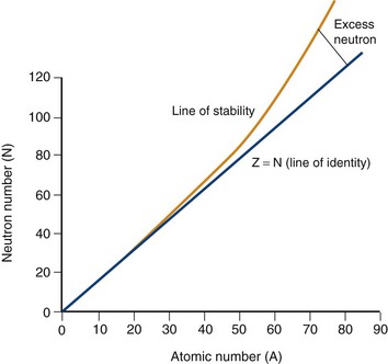
 FIGURE 20-2
Radioactivity: Electron Transition, Unstable Nuclei, and Radioactive Decay
Two types of ionization electron transition can occur. In heavy elements (elements with a high number of protons, or Z number), a characteristic x-ray is produced when an electron from an outer shell fills an inner shell vacancy (Fig. 20-3). The energy difference between two electron shells is characteristic of the element, given the different Z number and nuclear charge that define that element. The energy released as the characteristic x-ray represents the difference in potential energy between the outer shell electron and its new quantum state in the inner shell. The movement of an electron from an outer shell to an inner shell produces an x-ray with a characteristic energy, which can be described as a K, L, M, or N x-ray, and the energy of a characteristic x-ray from a particular element can be predicted based on the subatomic structure of the element. An example of a characteristic x-ray emission is the 68- to 70-keV mercury characteristic x-ray that is emitted from thallium 201.
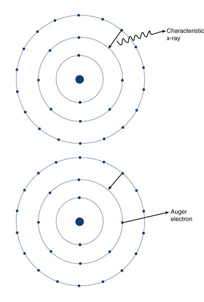
 FIGURE 20-3
Another mechanism of electron transition that leads to energy emission occurs when an outer shell electron fills an inner shell vacancy, but transfers the energy difference to an outer shell orbital electron (rather than emitting a characteristic x-ray), leading to the emission of an Auger electron (see Fig. 20-3). Because the release of an Auger electron leads to an orbital vacancy, a cascade of subsequent characteristic x-rays or further Auger electrons can occur after the initial emission. Auger electrons are usually produced when orbital electron vacancies are filled in elements of low Z number.
Radioactive decay can involve particulate and nonparticulate emissions. Different types of radioactive decay are described in Table 20-2 and include alpha particle emission, beta particle emission, positron emission, electron capture, gamma ray emission, and internal conversion.
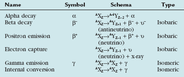
Beta particle emission occurs when a nucleus is unstable because of an elevated neutron/proton ratio (Fig. 20-4). When this occurs, a neutron is converted to a proton with the emission of an electron (β−) and an antineutrino (υ−). Because of the ejection of the electron and antineutrino from the nucleus, the daughter has an atomic number that is one greater than the parent. This decreases the instability generated by the elevated number of neutrons.
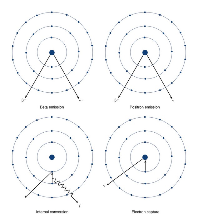
 FIGURE 20-4
In contrast to beta particle (β−) emission, when a nucleus is unstable because of an increased number of protons, radioactive decay can occur through positron emission (β+) or electron capture (see Fig. 20-4). A positron, which is effectively an electron with a positive charge, is emitted during times of proton excess with the simultaneous generation of a neutron. When a positron is emitted from the nucleus, it quickly encounters an electron in the environment, leading to the annihilation of both particles. This annihilation event converts all of the mass of the two particles into energy, with the subsequent generation of two photons of equal energy that travel at 180 degrees to each other. Because the total energy generated by the annihilation reaction is 1.02 MeV, each of the photons emitted from the reaction carries an energy of 511 keV. The high energy of these photons and their simultaneous generation allowing for coincidence detection underlie the mechanisms for positron emission tomography (PET).
A separate process by which a proton-rich nucleus can obtain nuclear stability is through electron capture (see Fig. 20-4). In electron capture, an inner shell electron combines with a nuclear proton to form a neutron, creating a more stable nucleus. An outer shell electron fills the vacant inner shell with the subsequent generation of characteristic x-rays or Auger electrons. Positron emission and electron capture are competitive processes, with β+ emission occurring more frequently in “lighter” elements, and electron capture occurring in “heavier” elements. The characteristic x-rays that are produced during thallium 201 decay (described previously) are produced through electron capture.
Gamma ray emission occurs during nuclear transformation when the process of radioactive decay does not completely dissipate the energy required for the atom to reach its most stable state. Gamma rays are a form of electromagnetic radiation with variable energy without mass or charge (i.e., a photon). Gamma rays carry off the excess nuclear energy through the process of isomeric transition. Isomeric transition occurs when a metastable nucleus is present from a prior radioactive decay. This can commonly occur after β− decay, but can also occur as a consequence of internal conversion (see Fig. 20-4), where an unstable nucleus transfers its energy to an inner shell (K or L) electron, leading to its expulsion as a conversion electron. An outer shell electron, releasing energy via a characteristic x-ray or Auger electron, fills the subsequent electron vacancy. The ability of gamma rays to penetrate tissue (and be used as an imaging tool) depends on their energy. An example of isomeric transition is the gamma photon emitted from the decay of the metastable Tc 99m nucleus.
 ) of the element, or the time it takes for a spontaneously decaying radionuclide to decrease its activity by 50%. The
  of a radionuclide is a function of its exponential rate of decay (dN/dt) or activity (A), and this rate of decay is specific for an element and related to the decay constant (λ) by:


 ), or:
Manufacture of Radionuclides
 9.3 hours) by a generator-based method. Most cyclotron-produced radionuclides have an elevated proton/neutron ratio, and decay by electron capture or positron emission. Because of its long
  (74 hours), thallium 201 can be transported from the cyclotron to the end-user.
In contrast to thallium 201, Tc 99m can be produced on-site using a commercially available generator (Fig. 20-5) from nuclear reactor–produced molybdenum 99. Molybdenum 99 is a fission reaction product of 235U. As molybdenum 99 slowly undergoes β− decay with a  of 66 hours, 87.5% of the decay product is Tc 99m, with the remaining 12.5% being the stable isomer Tc 99. When the generator is prepared at the radiopharmaceutical manufacturer, molybdenum 99 is tightly bound to a supporting alumina (Al2O3) column. Molybdenum 99 is more negatively charged than Tc 99m, and Tc 99m can be eluted (“milked”) from the column with normal saline into a collection vial as Tc 99m-pertechnetate.
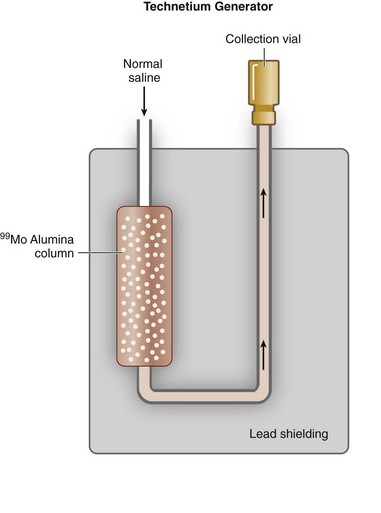
 FIGURE 20-5
 25.3 days). Similar to a Tc 99m generator, strontium 82 is adsorbed on a shielded column (stannic oxide), and rubidium 82 is eluted from the generator with normal saline. Because the
  of rubidium 82 is short (75 seconds), the generator elution occurs directly into the patient’s intravenous line. In addition to rubidium 82, other PET tracers may be used for assessment of cardiac perfusion, metabolism, and viability, including [2-18F]-2-fluoro-2-deoxyglucose (18FDG), [13N]-ammonia, [1-11C]-glucose, and [1-11C]-palmitate. These tracers are generated by a cyclotron, however, and because of their short half-lives, generally must be produced by an on-site cyclotron. The exception is 18FDG, which has a
  of 110 minutes and can be produced by a cyclotron in a radiopharmaceutical network for regional distribution.
Interactions with Matter
The interactions of radiation with matter depend on the type of radiation and the composition of the interacting matter. Generally, the interactions of charged particles with matter (alpha particles, beta particles, and electrons) can lead to ionization and excitation as described earlier. In addition, another charged particle interaction is called bremsstrahlung, which involves the interaction of charged particles (electrons) with the strong forces in the nucleus, leading to photon emission. Because most medical imaging involves photon (gamma and x-ray) detection, our discussion focuses on the three primary ways photons interact with matter: photoelectric effect, Compton scatter, and pair production (Fig. 20-6).
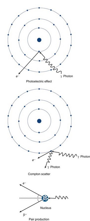
 FIGURE 20-6
The probability of a particular type of interaction between a photon and matter depends on the energy of the photon and the Z number of the material (Fig. 20-7). In elements with a high Z number, an interaction with a low-energy (<1 MeV) photon has a high likelihood of interacting via the photoelectric effect, whereas high-energy photons predominantly interact via pair production. Compton scatter occurs when photons carrying an energy in the range associated with radionuclides that are used in medical imaging (60 to 500 keV) interact with matter with a high density of loosely bound electrons (i.e., high physical density tissues such as bone) and is for the most part independent of the Z number of the absorbing material. The most likely effect of an imaging photon interaction within the human body before its arrival at the detection camera is one of Compton scatter.
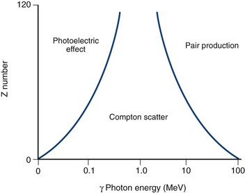
 FIGURE 20-7
INSTRUMENTATION AND SPECT IMAGING
The prototypic gamma detector is composed of the following elements (Fig. 20-8): collimator, scintillation crystal, light pipe, photomultiplier tubes, preamplifiers/amplifiers, pulse-height analyzer, positioning circuitry, analog-to-digital converter, and display device. A photon emitted from a patient must travel along a path that allows it to pass through the collimator holes where it encounters the scintillation crystal. In the scintillation crystal, the photon’s energy is converted to light. The photomultiplier tubes detect this light and generate an electrical signal relative to the intensity of the detected light. These electrical signals are individually detected and allow for determination of the originating location of the photon by the use of computerized electronics and algorithms, and are amplified and converted to a digital image. The details of each component of the gamma detector are discussed in sequence.
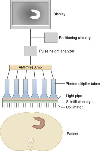
 FIGURE 20-8
Collimators
A collimator is a device that restricts the passage of photons into the scintillation crystal to select for photons traveling along particular paths. Because radionuclides emit photons in all directions, a collimator ensures that only photons traveling along the desired path from the patient are available for detection. Collimators are typically made of lead and are composed of multiple holes of defined diameter and depth, separated by intervening septa. To reach the scintillation crystal, photons must pass through one of these holes, traveling parallel to the long axis of the hole. Otherwise, the photons are absorbed by the septa. The most commonly used collimator type in SPECT imaging is a parallel-hole collimator (Fig. 20-9). Other types of collimators include slant-hole, converging, diverging, and pin-hole.
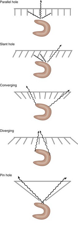
 FIGURE 20-9
The choice of a particular collimator depends on the object being imaged, the energy of the imaging photon, and the desired relationship between image sensitivity and resolution, with sensitivity defined as the percentage of emitted photons from a given source that are able to pass through the collimator and interact with the crystal. As part of the ability to restrict or permit photon transmission, collimators also affect the spatial resolution of the camera. The spatial resolution is usually measured by imaging a point source of radioactivity, and is measured as the width of a plot of image intensity (peak photon counts) versus distance and is expressed at one half of the maximum intensity (Fig. 20-10). This measurement of resolution is termed the full width half maximum (FWHM), with small FWHM values indicating that a camera can resolve two distinct points that are more closely spaced. For two different collimators with identical hole lengths, those with smaller diameter holes have lower sensitivity, but are able to resolve photon sources that are closely opposed. Similarly, thicker septa can also decrease sensitivity, but increase resolution. Most gamma camera systems used clinically today have a FWHM of approximately 9 mm for 140 keV Tc 99m gamma photons emitted 10 cm from the detector head. The most common collimator used in SPECT imaging is a parallel hole design, termed the low-energy all purpose collimator.
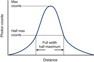
 FIGURE 20-10
Scintillation Crystals
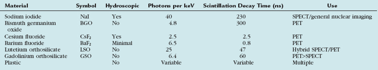
When a photon passes through a collimator, it interacts with the scintillation crystal. This crystal is made up of a material that converts the photon’s energy to a flash of light, also known as a “scintillation event.” The most common material used for scintillation crystals in gamma cameras is sodium iodide (NaI) doped with small amounts of thallium that enable the crystal to scintillate when struck with a photon. NaI crystals have a high probability of photoelectric interactions between photons with energies commonly used in imaging and produce light in proportion to the exciting photon’s energy. The excited electrons return to their stable quantum state with the release of energy as light, and the amount of light produced is proportional to the energy of the exciting photon. In the case of Tc 99m photons, the scintillation event produces a flash of 410-nm light. The crystal scintillates via excitation of the crystal’s electrons by Compton scatter or, most prominently, by the photoelectric effect. The potential disadvantages of NaI scintillation crystals are that they are hydroscopic (absorb moisture) and must be sealed and are very fragile. Other materials can also be used for scintillation crystals (Table 20-3).
Photomultiplier Tubes
Multiple photomultiplier tubes are arranged in an array on top of the scintillation crystal, coupled to the scintillation crystal by an optical glass–transparent gel interface that has the same refractive index as the scintillation crystal. This glass-gel coupling is termed the light pipe raising the photomultiplier tubes above the surface of the scintillation crystal. This height allows for multiple tubes to visualize a scintillation event, allowing the camera array to localize the scintillation event within the X, Y plane. Event localization is one of the hallmarks of the gamma camera and allows for generation of a SPECT image (Fig. 20-11).
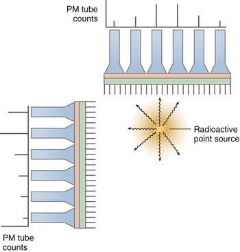
 FIGURE 20-11
Event Localization
A gamma camera uses the concept of proportional energy generation from scintillation events to ascribe arithmetically each event to a particular location within the crystal. This process was initially described by Anger,1 and is summarized as follows: Each scintillation event is simultaneously detected at multiple photomultiplier tubes, and the photomultiplier tube overlying the event receives the largest proportion of light generated from that event. Other photomultiplier tubes near to, but not directly overlying, the scintillation event receive proportionally less light from the event. The thickness of the light pipe enables simultaneous visualization of scintillation events by multiple photomultiplier tubes by elevating them a critical distance above the crystal. By integrating all of the signals from all of the photomultiplier tubes from each scintillation event using positioning circuitry, the X, Y coordinates of each scintillation event can be obtained. The “intrinsic resolution” of a particular gamma camera refers to the accuracy of the positioning circuitry and computer algorithms to determine the location of a scintillation event. “Extrinsic resolution” refers to the combination of the resolution of the collimator along with intrinsic resolution.
Quality Control
The performance and acquisition of reproducible and interpretable SPECT images using a gamma camera requires strict attention to quality control. Procedures are required to ensure that energy peaking, uniformity, linearity, resolution, and sensitivity fall within standard norms. The American Society of Nuclear Cardiology (www.asnc.org) has published guidelines on instrumentation quality assurance and performance,2 which detail these quality assurance issues.
Advances in SPECT Instrumentation
Despite the validated utility over the past 40 years of the traditional gamma (Anger) camera, advances in SPECT instrumentation technology in the coming years may dramatically alter how SPECT images are acquired and processed. These advances include multidetector imaging systems that allow for a smaller size imaging system, allowing imaging rooms to use less floor space. In addition, most SPECT imaging vendors are developing improved iterative reconstruction algorithms that allow for faster (two to four times) acquisition. Last, fundamental advances in photon detector technology have the potential to change fundamentally how SPECT images are obtained. Solid-state, semiconductor-based detectors, such as cadmium zinc telluride, have the potential to improve energy and spatial resolution, decrease scan times, reduce radiation exposure, and allow for simultaneous dual-isotope imaging in small footprint imaging systems. American Society of Nuclear Cardiology guidelines (available at www.asnc.org) on the incorporation of new imaging technology will help to define when and how these new technologies should be incorporated into standard clinical practice.


Chandra R. Nuclear Medicine Physics: The Basics, 6th ed. Baltimore: Lippincott Williams & Wilkins; 2004.
Cherry SR, Sorensen JA, Phelps MC. Physics in Nuclear Medicine, 3rd ed. Philadelphia: Saunders; 2003.
Hendee WR, Ritenour ER. Medical Imaging Physics, 4th ed. New York: Wiley-Liss; 2002.
Iskandrian AE, Verani MS. Nuclear Cardiac Imaging: Principles and Applications, 3rd ed. New York: Oxford University Press; 2003.
Stefaan T, Getkin A, Grinyov B, et al Radiation Detectors for Medical Applications, Vol 1. Dordrecht, The Netherlands, Springer, 2006.
* The views expressed in this chapter are those of the authors and do not reflect the official policy or position of the Department of the Navy, Department of Defense, or U.S. Government.
[/level-membership-for-cardiovascular-category][not-level-membership-for-cardiovascular-category]
CHAPTER 20 Physics and Instrumentation of Cardiac Single Photon Emission Computed Tomography
Successful performance and interpretation of cardiac single photon emission computed tomography (SPECT) studies relies on a basic understanding of the physics and instrumentation that allows for the generation of the images. The first practical system for the in vivo imaging of radionuclides was developed in the late 1950s by Anger and became commercially available in 1962.1 Despite more than 45 years of use and technical advances, the basic physics and design principles used today for cardiac SPECT imaging are remarkably similar to Anger’s initial concept.
PHYSICS AND SPECT IMAGING
Basic Atomic Structure
The classically described structure of an atom is known as the Bohr atom. It depicts a set of electrons orbiting the nucleus in stable electron shells (K, L, M, N) (Fig. 20-1). Each of the shells represents an energy state, with the innermost shell (K) associated with the greatest potential energy. Each electron’s energy state is defined further by a discrete set of four quantum numbers per electron. The Pauli exclusion principle states that no two electrons in the same atom can have an identical set of quantum numbers. By definition, a stable atom exists in its lowest possible energy state. When the energy state of an electron is increased (i.e., moved to a higher energy orbital shell or via absorption of external energy), the electron emits energy spontaneously as it returns to its lower, more stable energy state. This emission of energy by unstable electrons provides one mechanism for radionuclide imaging and is described in detail in the next section.
Electrons orbit a nucleus composed of a dense conglomerate of protons and neutrons that are bound together by a network of so-called strong nuclear forces. A proton contains a charge of 1.6 × 10⁻¹⁹ coulombs, which is the exact opposite charge of an electron. Neutrons are particles of slightly greater mass than protons, but are uncharged. The number of protons present in its nucleus, or Z number, defines each element, whereas the mass number, or A, represents the number of protons plus the number of neutrons. Specific nomenclature defines the relationship between the number of protons and neutrons in a nucleus (Table 20-1). The ratio of protons to neutrons defines the stability of a particular nucleus (Fig. 20-2); the transformation of an unstable nucleus to a more stable state is responsible for many of the radioactive emissions used in nuclear imaging.
| Name | Symbol | Description |
|---|---|---|
| Z number | ZX | Number of protons |
| A number | AX | Mass number; number of neutrons + protons |
| N number | N | Number of neutrons |
| Nuclide | Common elementary characteristics | |
| Isomer | m | Equal protons and neutrons, different energy state (e.g., Tc 99m) |
| Isotope | Same number of protons; Z1 = Z2 | |
| Isotone | Same number of neutrons; N1 = N2 | |
| Isobar | Same mass number; A1 = A2 |
Radioactivity: Electron Transition, Unstable Nuclei, and Radioactive Decay
Two types of ionization electron transition can occur. In heavy elements (elements with a high number of protons, or Z number), a characteristic x-ray is produced when an electron from an outer shell fills an inner shell vacancy (Fig. 20-3). The energy difference between two electron shells is characteristic of the element, given the different Z number and nuclear charge that define that element. The energy released as the characteristic x-ray represents the difference in potential energy between the outer shell electron and its new quantum state in the inner shell. The movement of an electron from an outer shell to an inner shell produces an x-ray with a characteristic energy, which can be described as a K, L, M, or N x-ray, and the energy of a characteristic x-ray from a particular element can be predicted based on the subatomic structure of the element. An example of a characteristic x-ray emission is the 68- to 70-keV mercury characteristic x-ray that is emitted from thallium 201.
Another mechanism of electron transition that leads to energy emission occurs when an outer shell electron fills an inner shell vacancy, but transfers the energy difference to an outer shell orbital electron (rather than emitting a characteristic x-ray), leading to the emission of an Auger electron (see Fig. 20-3). Because the release of an Auger electron leads to an orbital vacancy, a cascade of subsequent characteristic x-rays or further Auger electrons can occur after the initial emission. Auger electrons are usually produced when orbital electron vacancies are filled in elements of low Z number.
Radioactive decay can involve particulate and nonparticulate emissions. Different types of radioactive decay are described in Table 20-2 and include alpha particle emission, beta particle emission, positron emission, electron capture, gamma ray emission, and internal conversion.
Beta particle emission occurs when a nucleus is unstable because of an elevated neutron/proton ratio (Fig. 20-4). When this occurs, a neutron is converted to a proton with the emission of an electron (β−) and an antineutrino (υ−). Because of the ejection of the electron and antineutrino from the nucleus, the daughter has an atomic number that is one greater than the parent. This decreases the instability generated by the elevated number of neutrons.
In contrast to beta particle (β−) emission, when a nucleus is unstable because of an increased number of protons, radioactive decay can occur through positron emission (β+) or electron capture (see Fig. 20-4). A positron, which is effectively an electron with a positive charge, is emitted during times of proton excess with the simultaneous generation of a neutron. When a positron is emitted from the nucleus, it quickly encounters an electron in the environment, leading to the annihilation of both particles. This annihilation event converts all of the mass of the two particles into energy, with the subsequent generation of two photons of equal energy that travel at 180 degrees to each other. Because the total energy generated by the annihilation reaction is 1.02 MeV, each of the photons emitted from the reaction carries an energy of 511 keV. The high energy of these photons and their simultaneous generation allowing for coincidence detection underlie the mechanisms for positron emission tomography (PET).
A separate process by which a proton-rich nucleus can obtain nuclear stability is through electron capture (see Fig. 20-4). In electron capture, an inner shell electron combines with a nuclear proton to form a neutron, creating a more stable nucleus. An outer shell electron fills the vacant inner shell with the subsequent generation of characteristic x-rays or Auger electrons. Positron emission and electron capture are competitive processes, with β+ emission occurring more frequently in “lighter” elements, and electron capture occurring in “heavier” elements. The characteristic x-rays that are produced during thallium 201 decay (described previously) are produced through electron capture.
Gamma ray emission occurs during nuclear transformation when the process of radioactive decay does not completely dissipate the energy required for the atom to reach its most stable state. Gamma rays are a form of electromagnetic radiation with variable energy without mass or charge (i.e., a photon). Gamma rays carry off the excess nuclear energy through the process of isomeric transition. Isomeric transition occurs when a metastable nucleus is present from a prior radioactive decay. This can commonly occur after β− decay, but can also occur as a consequence of internal conversion (see Fig. 20-4), where an unstable nucleus transfers its energy to an inner shell (K or L) electron, leading to its expulsion as a conversion electron. An outer shell electron, releasing energy via a characteristic x-ray or Auger electron, fills the subsequent electron vacancy. The ability of gamma rays to penetrate tissue (and be used as an imaging tool) depends on their energy. An example of isomeric transition is the gamma photon emitted from the decay of the metastable Tc 99m nucleus.
