[level-membership-for-pediatrics-category]Chapter 69
Pediatric Cardiac Catheterization and Electrophysiology
Pediatric Cardiac Catheterization
During the past few decades, noninvasive imaging techniques including echocardiography, magnetic resonance angiography, and computed tomography angiography have evolved significantly in the assessment of complex congenital cardiovascular anatomy. Consequently, use of the catheterization laboratory has evolved to include both diagnostic procedures to assess complex congenital abnormalities before surgery and interventional procedures that permit therapeutic options and often preclude surgery.1
Semilunar Valve Stenosis and Balloon Valvuloplasty
Since transcatheter balloon pulmonary valvuloplasty for valvar pulmonary stenosis in infants was first reported in the early 1980s, it has become the first line of therapy. The recommended balloon/annulus diameter ratio is 120%.2 The reported success rate is greater than 90%, with major adverse events occurring in fewer than 1% of the procedures.3 Hemodynamic measurements include the right ventricular pressure compared with systemic arterial pressure and the peak-to-peak systolic pressure gradient across the pulmonary valve. The indication for balloon pulmonary valvuloplasty is the presence of at least moderate pulmonary valve stenosis. We use as a guideline the “rule of 50,” which is defined as a peak right ventricular systolic pressure of more than 50 mm Hg, a peak right ventricular systolic pressure more than 50% of the systemic systolic pressure, or a peak-to-peak systolic gradient across the pulmonary valve of more than 50 mm Hg.
Valvar aortic stenosis can be classified into two groups: disease that is severe enough that it presents at birth or within 1 year of age (10% to 15%), and disease that is not diagnosed until after age 2 years and will progress much more slowly, if at all.4,5 Mortality and the need for intervention are significantly skewed toward the infantile group. As with pulmonary stenosis, noninvasive imaging techniques have advanced to the point that nearly all anatomic and functional information about the valve may be obtained without catheterization. Catheterization is performed for valves that clearly merit intervention or when symptoms and imaging findings are incomplete or confounding.
Balloon or Stent Angioplasty
Transcatheter stent angioplasty for postoperative recoarctation of the aorta at the isthmus has been demonstrated to be safe and effective.5 The technique usually involves a femoral arterial approach. An exchange length wire is placed in the ascending aorta or right subclavian artery. An angioplasty balloon is used with a maximum diameter that is equal to or less than the diameter of the normal aortic segments adjacent to the stenotic region and/or the diameter of the descending thoracic aorta at the diaphragm. The stent is mounted on the angioplasty balloon and passed through a sheath at least 1 to 2 Fr larger than that required by the balloon. The stent length is dependent on the lesion length but usually is at least 36 mm in adults. The stent is fully dilated in most cases, but at times it is deemed safer to serially dilate the lesion over two procedures.
Septal and Vascular Occlusion Devices
Although diagnosing the presence of an atrial septal defect (ASD) rarely requires cardiac catheterization, today many patients are undergoing cardiac catheterization for therapeutic device closure.6 These patients require assessment of associated anomalies such as abnormalities of pulmonary venous connections. A step-up in oxygen saturations in the right atrium and pulmonary arteries is characteristic for an ASD, and the degree of left-to-right shunting or the pulmonary to systemic blood flow ratio (Qp : Qs) can be determined. The ideal age or timing for elective ASD closure is 2 to 5 years of age or within 6 to 12 months of diagnosis. Rarely, a child with an ASD presents with severe congestive heart failure and requires intervention in the first year of life.
The world experience of transcatheter ASD closure using the Food and Drug Administration–approved Amplatzer Septal Occluder (AGA Medical Corporation, Golden Valley, MN) has been reported with a greater than 97% immediate success rate.7 The occlusion rate reached 100% by 3 years. An overall 2.8% adverse event rate was found, and no procedural deaths occurred. Several studies regarding comparisons of device occlusion versus surgical closure have been performed prospectively. These reports include the Amplatzer and Helex (W.L. Gore & Associates, Flagstaff, AZ) devices for ASD closure. Findings include shorter hospital stays, less discomfort, and shorter durations for convalescence in patients undergoing successful closure with use of a device. Hospital costs are similar. Regression of right ventricular dilatation was similar for both groups of patients; however, it was dependent on the patient’s age at the time of closure, with greater regression following earlier intervention.
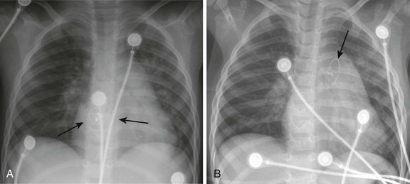
Procedural adverse events are uncommon but include embolization into the right or left atrium, pulmonary artery, left ventricle, and aorta; stroke as a result of a clot or air embolization; and bleeding complications.8 Both acute and late embolization have been reported, and thus it is critical for the radiologist to be familiar with the location of the interatrial septum on radiography to ascertain correct device position in the anteroposterior and lateral chest radiograph. Figure 69-1, A, demonstrates a septal occluder device in the appropriate position within the interatrial septum, and Figure 69-1, B, demonstrates the device positioned incorrectly in the left pulmonary artery.
The first transcatheter interventional procedure was closure of a persistently patent ductus arteriosus (PDA), which was performed by Portsmann in 1967. Since that time a number of different PDA closure devices have been studied, some of which are no longer available. The goal of the procedure has always been to achieve 100% closure of the PDA without obstruction of either adjoining blood vessel (i.e., the aorta and the left pulmonary artery) with minimal risk of complications. The difficulty is that the PDA exhibits extreme variability in size and shape. Krichenko et al.9 classified the PDA into five anatomic types based on the lateral aortic angiogram. The most common (“type A”) ductus is conical with a narrowed pulmonary arterial end and large aortic ampulla. Other types include those with a narrowed aortic end, narrowing at both ends, and a tubular configuration. Early device closure procedures were complicated by a lack of choices for vessels of different sizes and shapes. The early devices had unsatisfactory rates of complications and residual leaks and were abandoned. In 1992, the first report was published using the Gianturco embolization coil (Cook Medical, Bloomington, IN) for closure of small PDAs. The Gianturco coil, which is available in multiple lengths and diameters, has now been in use for more than 20 years for blood vessel occlusion, including unwanted collateral vessels, fistulae, and arteriovenous malformations. The successful use of the coil in PDA closure, combined with sharing of ingenious techniques to deploy multiple coils and secure the coils before deployment by individual operators, provided the needed variety of approaches for successful PDA closure. At present, tens of thousands of patients around the world have had PDAs closed with embolization coils.
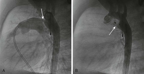
A more recent addition to the interventional cardiologist’s armamentarium for PDA closure is the Amplatzer Duct Occluder.10 The PDA occluder is a self-expanding wire mesh device that is attached to a delivery cable and deployed through a long sheath from the venous system. Figure 69-2, A, demonstrates a lateral projection angiogram of the descending thoracic aorta and a left-to-right shunting PDA. Figure 69-2, B, demonstrates device occlusion of the PDA. The device has a retention skirt to occupy the aortic ampulla and tapers slightly to the pulmonary artery end. The device is filled with a polyester mesh that stimulates thrombus formation within the lumen of the PDA. The shape of the device and self-expanding properties exert radial force on the walls of the PDA, holding the device in place until endothelialization occurs. The device has excellent closure rates approaching 100% at 1 month after the procedure. The main limitation is the size and bulky nature of the device. The PDA must have an aortic ampulla adequate to accommodate the retention skirt without creating aortic obstruction. Furthermore, the device can create left pulmonary artery stenosis by compressing adjoining structures once it is released.
Pediatric Electrophysiology
Catheter Ablation in Children
The surgical elimination of an accessory atrioventricular pathway in 1968 heralded the era of curative therapy of tachycardia substrates.11 Transvascular catheter delivery of direct current to create atrioventricular block in adults with troublesome atrial fibrillation was first reported in 1983.12 However, the modern era of catheter ablation began in 1987 with the use of alternating current in the radiofrequency range (about 550 kHz) to ablate an accessory pathway.13 Unlike direct current, radiofrequency current causes resistive heating, thus creating a fairly well-circumscribed lesion and minimizing collateral damage. This technology rapidly expanded to include children14 and patients with congenital heart disease.15 Almost no tachyarrhythmia substrate is now considered exempt from catheter ablation therapy thanks to newer catheter designs, new electroanatomic mapping technologies, and additional energy sources, especially cryoenergy. Indications to perform catheter ablation in children remain somewhat limited by the benign natural history of some tachyarrhythmia substrates,16 continued concern of damage to nearby structures, and concern for scar expansion with somatic growth.17 The arrhythmia substrates that commonly undergo ablation in children appear in e-Table 69-1, and published indications for performing ablation appear in e-Box 69-1.18
e-Table 69-1
Tachyarrhythmia Types and Anatomic Targets for Catheter Ablation
| Tachyarrhythmia Type | Substrate Target |
| Atrial flutter | Zone of slow conduction between conduction barriers |
| Atrial ectopic tachycardia | Focus of earliest activation |
| Atrioventricular reciprocating tachycardia | Accessory pathway |
| Atrioventricular nodal reentry tachycardia | “Slow inputs” to the atrioventricular node |
| Ventricular tachycardia in the normal heart | Focus of earliest activation |
| Ventricular tachycardia after congenital heart surgery | Zone of slow conduction between conduction barriers |
Technical Considerations
The guiding principle of electrophysiologic testing and catheter ablation involves coupling of anatomic structures to electrical phenomena. Most cases can be accomplished with standard fluoroscopy and multiple multielectrode catheters positioned in the right ventricle, right atrium, coronary sinus, and His bundle region of the tricuspid valve annulus, with one for mapping and ablation (Fig. 69-3). In a normal heart, these anatomic sites can be easily accessed from a combination of femoral, internal jugular, and subclavian venous approaches. However, in some patients with complex congenital cardiovascular anomalies (e.g., interrupted inferior vena cava in some patients with heterotaxy) and in others having undergone certain congenital heart operations (e.g., cavopulmonary connection or extracardiac conduit in patients having single ventricle physiology), some or all of these venous sites will not allow access to the heart. Moreover, patients who have undergone multiple prior procedures may have permanent venous occlusion of some of these access pathways. In these instances, alternate approaches may include transhepatic venous,19 arterial/retroaortic, and transthoracic access.20 Furthermore, occasional arrhythmia substrates are primarily epicardial, requiring transpericardial access. Transthoracic or intracardiac echocardiography21 may aid in understanding anatomic details and in the positioning of catheters.
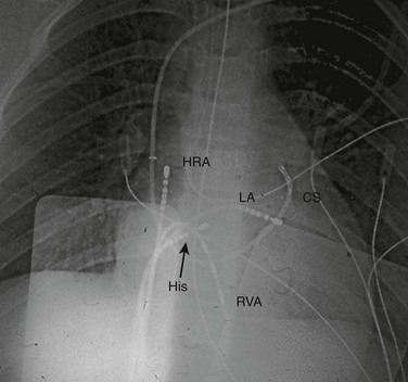
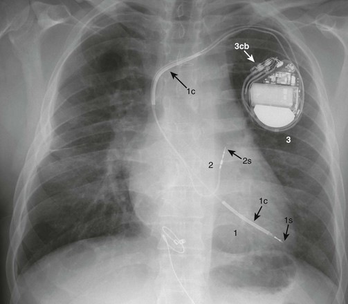
Figure 69-3 Anterior-posterior projection of a chest fluorograph during a radiofrequency catheter ablation procedure in a teenager with Wolff-Parkinson-White syndrome and a left lateral accessory pathway.
Standard multipole electrode catheters are positioned in the high right atrium (HRA), across the tricuspid valve in the His bundle region (His), in the right ventricular apex (RVA), in the coronary sinus (CS), and at the mapped location of the accessory pathway along the mitral valve annulus (accessed from the left atrium [LA] via transseptal puncture).
The CARTO system (Biosense Webster, Diamond Bar, CA) allows an endocardial map to be created using a low-energy, triple-source transmitter located on a position pad mounted beneath the patient, a receiver in the tip of the specialized mapping/ablation catheter, and global positioning system technology. A second electrode catheter in a fixed intracardiac position serves as a temporal reference, thus permitting electroanatomic coupling by the mapping catheter as it is manipulated to create an anatomic rendition of the chamber(s) of interest. Isochronal activation, isopotential, and animated activation maps may be produced (e-Fig. 69-4).
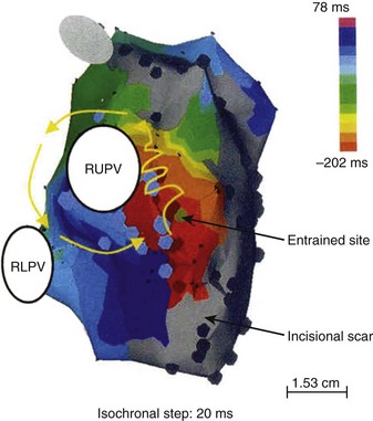
e-Figure 69-4 Electroanatomic reconstruction of the pulmonary venous atrium from a right posterior oblique projection using the CARTO system with a patient who has undergone the Mustard operation for d-transposition of the great arteries and who has atrial flutter.
The color-coded isochrones indicate a reentry circuit around the ostium of the right upper pulmonary vein (RUPV). Areas colored gray imply regions with sufficiently low voltages to suggest scar. RLPV, Right lower pulmonary vein ostium. (From Zrenner B, Dong J, Schreieck J et al. Delineation of intra-atrial reentrant tachycardia circuits after mustard operation for transposition of the great arteries using biatrial electroanatomic mapping and entrainment mapping, J Cardiovasc Electrophysiol 14:1302-1310, 2003.)
The Ensite system (St. Jude Medical, St. Paul, MN) uses a noncontact multielectrode array that is mounted on a balloon catheter and centrally positioned in the chamber of interest (intracavitary). Ring electrodes on this catheter, proximal and distal to the array, serve as receivers from a low-current “locator” signal delivered from any second standard electrode catheter. As this second catheter is rapidly swept along all endocardial surfaces of the chamber of interest, a 3D computer model of the endocardium is generated. Far-field electrical activity recorded from each electrode on the array is enhanced and resolved based on an inverse solution to Laplace’s equation. The inverse solution considers how a signal detected at a remote point (the array) will appear at its source (endocardial surface), thus superimposing a real-time isopotential map on the geometry matrix, even from a single heartbeat (e-Fig. 69-5).22
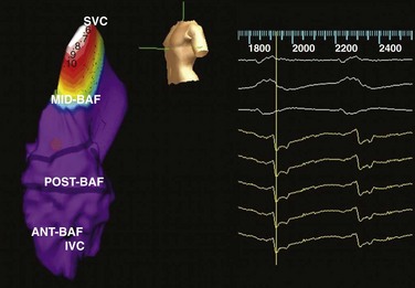
e-Figure 69-5 Electroanatomic reconstruction of the systemic venous atrium (intercaval region) from a left posterior oblique projection using the Ensite system after the Mustard operation for d-transposition of the great arteries in a patient who has atrial flutter.
This isopotential map features brighter colors (white = brightest) representing higher voltages and illustrates regions of depolarization over time (reading from left to right). The purple regions are presumably electrically refractory or inexcitable. Ant-Baf, Anterior portion of baffle; IVC, inferior vena cava; Mid-Baf, mid portion of baffle; Post-Baf, posterior portion of baffle; SVC, superior vena cava. (Modified from and courtesy Dr. Maully Shah.)
Both of these systems now have the capacity to merge previously obtained digital imaging and communication in medicine–formatted computerized tomographic or magnetic resonance images (MRI) of the patient’s heart chambers with the real-time anatomic renderings previously described (e-Fig. 69-6).
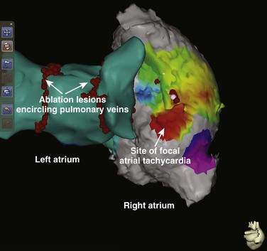
e-Figure 69-6 Posterior projection of composite biatrial rendering from a patient who has both atrial fibrillation and focal atrial tachycardia.
The left atrial geometry was generated by a standard electroanatomic technique, but the right atrial geometry represents merging of a chest computed tomography–generated digital imaging and communication in medicine image with the electroanatomic data. (Courtesy Dr. James Daubert.)
Radiation Exposure
Fluoroscopy remains the workhorse for cardiac catheter ablation procedures in most institutions. Under the direction of John Kugler, the Pediatric Electrophysiology Society began a pediatric radiofrequency registry in 1990, which has demonstrated a progressive reduction in procedural fluoroscopy duration from 61.5 minutes in 199414 to 38.3 minutes in 2004,23 at least among patients with supraventricular tachycardia. Most operators limit x-ray exposure by reducing frame rates to 15 and even 7.5 frames/sec and by minimizing the use of magnification. That said, clever use of electroanatomic mapping systems may markedly reduce the duration of fluoroscopy.22,24 St. Jude Medical’s Ensite NavX system permits continuous, real-time, 3D rendering of all electrode catheters, anatomic features, and tagged structures (including locations of previously delivered ablation lesions) with use of a global positioning system–like technology, which is facilitated by three pairs of skin surface patches, serving as x-y-z axis low-energy transmitters. Using continuous impedance measurements, the electrode catheters are the receivers. Virtual elimination of ionizing radiation for simple catheter ablation procedures has been reported with use of this system.25
Data on actual x-ray exposure during catheter ablation procedures comes largely from adult series, in which thermoluminescent dosimeters and/or anthropomorphic radiologic phantoms were used.26–30 Considering fluoroscopy times ranging from 41 to 60 minutes, a single procedure has been estimated to carry a risk of fatal malignancy in 0.03% to 0.13% of individuals and to result in birth defects in 0.00012%.27,28,30 These figures are approximately equivalent to 1% and 0.1% of the spontaneous incidences, respectively. Geise and colleagues31 reported that radiation doses to exposed skin were 6.2 to 49 mGy/min in nine children, which calculated to total doses of 0.09 to 2.35 Gy. In our laboratory, our median fluoroscopy time is 32 minutes per case, and we limit fluoroscopy times to 120 minutes, even for complicated cases.
Device Therapy in Children
Fundamentals of Pacing Hardware
Bradycardia devices (i.e., pacemakers) and antitachycardia devices (i.e., implantable cardioverter defibrillators [ICDs]) require two basic hardware components, the pulse generator and conductors (primarily, “leads”). The pulse generator consists of an energy source (battery), microcircuitry, titanium alloy housing, and a plastic connector block for conductor attachment. In addition, the ICD contains capacitors to store deliverable energy. The lead consists of one (unipolar) or two (bipolar) wires, silicon or polyurethane insulation, a connector pin (or pins) that insert(s) into the pulse generator connector block, and a fixation end that attaches to myocardium (via a tiny screw, fish hook, plaque, or other device). Transvenous bipolar leads generally have a radiodense distal electrode and a slightly more proximal “ring” electrode, whereas the unipolar lead has only a distal electrode. Epicardial leads are mostly unipolar, but bifurcated plaque electrodes and in-line bipolar leads also exist. In addition, the ventricular lead for an ICD may have one or two additional insulated conductors that are exposed on the outer surface of the lead (so-called coils) and participate in the shock field. Arrays and patches may be necessary to optimize cardioversion or defibrillation and are inserted in subcutaneous or intrapericardial sites. Figures 69-7 and 69-8 illustrate the radiographic appearance of this hardware. An entirely subcutaneous cardioverter-defibrillator (which can sense and shock only) is currently in clinical trials.
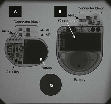
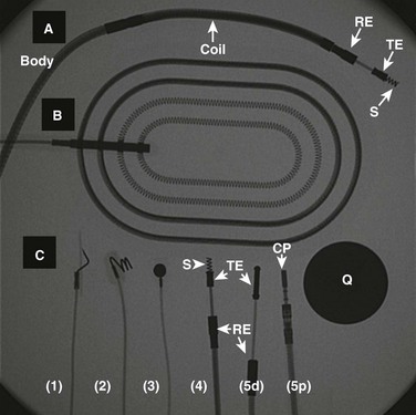
Figure 69-8 A fluoroscopic image of several types of conductors used for cardiac device therapy in children and teenagers.
A, A transvenous, active fixation, bipolar, ventricular lead used with implantable cardioverter-defibrillators (ICDs) and containing a coil for participation in shock delivery. B, A patch, which is placed in either pericardial or subcutaneous locations, and is used with ICDs for participation in shock delivery. C, A variety of leads used with either pacemakers or ICDs. 1, The distal (cardiac) end of a unipolar, epicardial active fixation (stab-on or fish hook) lead. 2, The distal end of a unipolar, epicardial active fixation (screw-in) lead. 3, The distal end of a unipolar, epicardial passive fixation (plaque, suture-on) lead. 4, The distal end of a bipolar, transvenous active fixation lead (with a retractable screw). 5d and 5p illustrate the distal (cardiac) and proximal (connector block of pacemaker) ends of a bipolar, passive fixation lead, respectively. CP, Connector pin; Q, quarter (for size comparison); RE, ring electrode; S, screw; TE, tip electrode.
Radiography of Pacing Systems
A systematic approach will enable the radiologist to interpret the appearance of the hardware. The first step is to identify the location of the pulse generator. When the device is infraclavicular, the conductors usually are transvenous. Epicardial leads are generally tunneled to a subcutaneous abdominal device, but subcostal and flank locations (especially in premature infants) also may be used. Hybrid systems imply use of a combination of transvenous, epicardial, and/or subcutaneous conductors, configured to accommodate restricted venous access, and/or a preexisting lead that is considered valuable, and/or an optimized shock vector in the case of ICDs. The pulse generator will be positioned in a location optimal to the complex configuration of the conductors. The second step is to describe each conductor, including the type (e.g., lead, lead with coils, array, or patch), its course from the pulse generator to the heart or other thoracic site, its form of attachment to the heart in the case of leads, and whether the lead is unipolar or bipolar. Magnification of the lead tip may be required. In young children with epicardial lead(s), redundant lead body is coiled anterior to the heart. Lead may be partially looped within the right atrium in the case of transvenous leads (the so-called growth loop). The third step is to correlate the congenital and surgical anatomy with lead locations and courses. Understanding the appropriateness of the course of each lead often requires some knowledge of the surgical anatomy. Figures 69-9 and 69-10, and e-Figure 69-11 illustrate the radiographic appearance of patients who have complex cardiac device therapy. Finally, leads attached to both right and left ventricles suggest an attempt at ventricular resynchronization as a result of ventricular dysfunction. The left ventricular lead may be transvenous to the coronary sinus or epicardial surface of the heart.
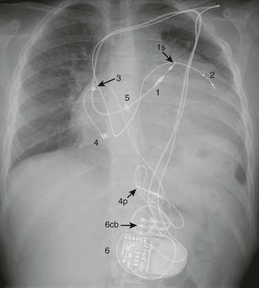
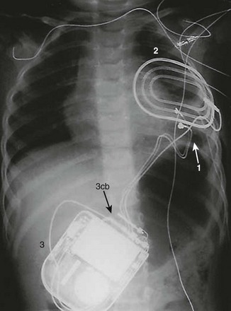
Figure 69-10 A posterior-anterior chest radiograph from a 3-month-old male infant with ventricular tachycardia associated with Brugada syndrome.
1, An epicardial, bifurcated (hence, bipolar), passive fixation (plaque electrodes) lead positioned on the left ventricle for purposes of ventricular pacing and sensing. 2, A patch placed posteriorly and in a subcutaneous location for participation in possible shock delivery. 3, An implantable cardioverter-defibrillator (ICD) in a subcutaneous pocket over the left abdomen (3cb, ICD connector block).
e-Figure 69-11 A posterior-anterior chest radiograph from a 19-year-old who had a Senning operation for d-transposition of the great arteries, sinus node dysfunction, and a history of ventricular tachycardia.
1, A transvenous, active fixation lead that is attached to the left ventricular apex (systemic venous ventricle) by a retractable screw (1s). The lead contains two coils (1c) that will participate in possible shock delivery. 2, A transvenous, bipolar, active fixation lead that is attached to the roof of the left atrium (systemic venous atrium) by a retractable screw (2s). 3, An implantable cardioverter-defibrillator (ICD) (3cb, ICD connector block).
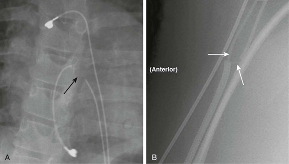
In children undergoing chronic device therapy, symptoms suggestive of device malfunction may develop, such as syncope, skeletal muscle twitching, hiccoughs, new onset of fatigue, palpitations, and, in the case of ICDs, inappropriate shocks. Radiographic abnormalities that may suggest the etiology include lead conduction fracture, lead dislodgement (especially if symptoms occur soon after implantation), lead stretch as a result of somatic growth, and connector pin separation from pulse generator. Transvenous leads usually fracture beneath the clavicle, and epicardial leads tend to fracture at the level of the diaphragm or within the active fixation component (especially when it is a screw). A caveat: The Medtronic model 4968 (Medtronic, Minneapolis, MN) bifurcated, epicardial, double-plaque lead always has the appearance of near-fracture at the union of the two conductors (Fig. 69-12). Finally, the radiologist may be called upon to identify the type of implanted device (i.e., the manufacturer and model number) that is in a patient. Each pulse generator has a radiodense alphanumeric identifier (often its model number) that can be referenced in any of the major companies’ device encyclopedias (see Fig. 69-7). Unfortunately, if the face of the device is facing posteriorly or if sufficient obliquity is present, it may not be readable.
Caring for Children with Devices While in the Radiology Department
Cardiac devices became interactive with the first inclusion of demand circuitry, which was developed in 1965 to allow sensing of intrinsic electrical activity. We now communicate with these devices for purposes of reprogramming, functional testing, and telemetry using a computerized programmer and radiofrequency signals. Hence, despite various forms of protective shielding and electronic filters, all devices may be affected by certain sources of electromagnetic interference (EMI) that may be present in the radiology department. It should be emphasized that ionizing radiation used for diagnostic procedures usually is not a source of EMI. High-dose x-rays during computerized tomography, only when applied directly to the device, can rarely result in oversensing.32 This effect theoretically can inhibit a device, resulting in loss of output. However, the effect is transient and reverses as the beam moves away from the device.
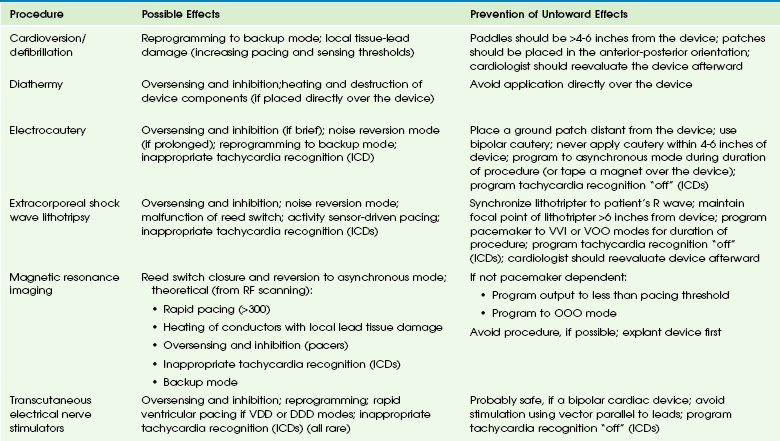
Repeated high-dose radiation therapy may damage the silicone and silicone oxide insulation necessary for the complementary metal oxide semiconductor chip technology of cardiac devices. Device manufacturers have provided guidelines to minimize risk of damage to ICDs resulting from radiotherapy.33 EMI-device interactions may result from MRI, defibrillation, electrocautery, peripheral nerve stimulation, transcutaneous electrical nerve stimulation, diathermy, radiofrequency ablation, and lithotripsy. Untoward responses by the device may include oversensing, noise reversion, power-on reset, permanent circuit failure, and damage to the lead-tissue interface, causing a permanent rise in the stimulation threshold. A glossary of these terms appear in e-Box 69-2. Some of these potentially harmful medical procedures, specific responses to EMI, and ways to prevent these responses appear in e-Table 69-2.34 MRI theoretically may cause device malfunction as a result of static magnetic, gradient, and radiofrequency fields and may cause tissue heating at the conductor-cardiac interface. Nevertheless, the performance of a nonthoracic MRI (at 1.5 T) in a patient with a pacemaker35 or ICD36 has been upgraded to a relative, not absolute, contraindication. An MRI-compatible pacemaker (but not ICD) manufactured by Medtronic also recently has become available.
References
1. Feltes, TF, Bacha, E, Beekman, RH, 3rd., et al. Indications for cardiac catheterization and intervention in pediatric cardiac disease: a scientific statement from the American Heart Association. Circulation. 2011;123:2607–2652.
2. Bonow, RO, Carabello, BA, Kanu, C, et al. ACC/AHA 2006 guidelines for the management of patients with valvular heart disease: a report of the American College of Cardiology/American Heart Association Task Force on Practice Guidelines. Circulation. 2006;114:e84–e231.
3. Lababidi, Z, Wu, JR. Percutaneous balloon pulmonary valvuloplasty. Am J Cardiol. 1983;52:560–562.
4. Vida, VL, Bottio, T, Milanesi, O, et al. Critical aortic stenosis in early infancy: surgical treatment for residual lesions after balloon dilation. Ann Thorac Surg. 2005;79:47–51. [discussion 51-5-2].
5. Holzer, R, Qureshi, S, Ghasemi, A, et al. Stenting of aortic coarctation: acute, intermediate, and long-term results of a prospective multi-institutional registry—Congenital Cardiovascular Interventional Study Consortium (CCISC). Catheter Cardiovasc Interv. 2010;76:553–563.
6. Jones, TK, Latson, LA, Zahn, E, et al. Results of the U.S. multicenter pivotal study of the HELEX septal occluder for percutaneous closure of secundum atrial septal defects. J Am Coll Cardiol. 2007;49:2215–2221.
7. Omeish, A, Hijazi, ZM. Transcatheter closure of atrial septal defects in children & adults using the Amplatzer Septal Occluder. J Interv Cardiol. 2001;14:37–44.
8. Williams, RJ, Levi, DS, Moore, JW, et al. Radiographic appearance of pediatric cardiovascular transcatheter devices. Pediatr Radiol. 2006;36:1231–1241. [quiz 332-333].
9. Krichenko, A, Benson, LN, Burrows, P, et al. Angiographic classification of the isolated, persistently patent ductus arteriosus and implications for percutaneous catheter occlusion. Am J Cardiol. 1989;63:877–880.
10. Brunetti, MA, Ringel, R, Owada, C, et al. Percutaneous closure of patent ductus arteriosus: a multiinstitutional registry comparing multiple devices. Catheter Cardiovasc Interv. 2010;76:696–702.
11. Cobb, FR, Blumenschein, SD, Sealy, WC, et al. Successful surgical interruption of the bundle of Kent in a patient with Wolff-Parkinson-White syndrome. Circulation. 1968;38:1018–1029.
12. Wood, DL, Hammill, SC, Holmes, DR, Jr., et al. Catheter ablation of the atrioventricular conduction system in patients with supraventricular tachycardia. Mayo Clin Proc. 1983;58:791–796.
13. Borggrefe, M, Budde, T, Podczeck, A, et al. High frequency alternating current ablation of an accessory pathway in humans. J Am Coll Cardiol. 1987;10:576–582.
14. Kugler, JD, Danford, DA, Deal, BJ, et al. Radiofrequency catheter ablation for tachyarrhythmias in children and adolescents, The Pediatric Electrophysiology Society. N Engl J Med. 1994;330:1481–1487.
15. Van Hare, GF, Lesh, MD, Stanger, P. Radiofrequency catheter ablation of supraventricular arrhythmias in patients with congenital heart disease: results and technical considerations. J Am Coll Cardiol. 1993;22:883–890.
16. Naheed, ZJ, Strasburger, JF, Benson, DW, Jr., et al. Natural history and management strategies of automatic atrial tachycardia in children. Am J Cardiol. 1995;75:405–407.
17. Saul, JP, Hulse, JE, Papagiannis, J, et al. Late enlargement of radiofrequency lesions in infant lambs. Implications for ablation procedures in small children. Circulation. 1994;90:492–499.
18. Friedman, RA, Walsh, EP, Silka, MJ, et al. NASPE Expert Consensus Conference: Radiofrequency catheter ablation in children with and without congenital heart disease. Report of the writing committee. North American Society of Pacing and Electrophysiology. Pacing Clin Electrophysiol. 2002;25:1000–1017.
19. Fischbach, P, Campbell, RM, Hulse, E, et al. Transhepatic access to the atrioventricular ring for delivery of radiofrequency energy. J Cardiovasc Electrophysiol. 1997;8:512–516.
20. Nehgme, RA, Carboni, MP, Care, J, et al. Transthoracic percutaneous access for electroanatomic mapping and catheter ablation of atrial tachycardia in patients with a lateral tunnel Fontan. Heart Rhythm. 2006;3:37–43.
21. Peichl, P, Kautzner, J, Gebauer, R. Ablation of atrial tachycardias after correction of complex congenital heart diseases: utility of intracardiac echocardiography. Europace. 2009;11:48–53.
22. Schilling, RJ, Peters, NS, Davies, DW. Simultaneous endocardial mapping in the human left ventricle using a noncontact catheter: comparison of contact and reconstructed electrograms during sinus rhythm. Circulation. 1998;98:887–898.
23. Van Hare, GF, Javitz, H, Carmelli, D, et al. Prospective assessment after pediatric cardiac ablation: Demographics, medical profiles, and initial outcomes. J Cardiovasc Electrophysiol. 2004;15:759–770.
24. Papez, AL, Al-Ahdab, M, Dick, M, 2nd., et al. Impact of a computer assisted navigation system on radiation exposure during pediatric ablation procedures. J Interv Card Electrophysiol. 2007;19:121–127.
25. Smith, G, Clark, JM. Elimination of fluoroscopy use in a pediatric electrophysiology laboratory utilizing three-dimensional mapping. Pacing Clin Electrophysiol. 2007;30:510–518.
26. Lickfett, L, Mahesh, M, Vasamreddy, C, et al. Radiation exposure during catheter ablation of atrial fibrillation. Circulation. 2004;110:3003–3010.
27. Lindsay, BD, Eichling, JO, Ambos, HD, et al. Radiation exposure to patients and medical personnel during radiofrequency catheter ablation for supraventricular tachycardia. Am J Cardiol. 1992;70:218–223.
28. Perisinakis, K, Damilakis, J, Theocharopoulos, N, et al. Accurate assessment of patient effective radiation dose and associated detriment risk from radiofrequency catheter ablation procedures. Circulation. 2001;104:58–62.
29. Kovoor, P, Ricciardello, M, Collins, L, et al. Radiation exposure to patient and operator during radiofrequency ablation for supraventricular tachycardia. Aust N Z J Med. 1995;25:490–495.
30. Kovoor, P, Ricciardello, M, Collins, L, et al. Risk to patients from radiation associated with radiofrequency ablation for supraventricular tachycardia. Circulation. 1998;98:1534–1540.
31. Geise, RA, Peters, NE, Dunnigan, A, et al. Radiation doses during pediatric radiofrequency catheter ablation procedures. Pacing Clin Electrophysiol. 1996;19:1605–1611.
32. McCollough, CH, Zhang, J, Primak, AN, et al. Effects of CT irradiation on implantable cardiac rhythm management devices. Radiology. 2007;243:766–774.
33. Solan, AN, Solan, MJ, Bednarz, G, et al. Treatment of patients with cardiac pacemakers and implantable cardioverter-defibrillators during radiotherapy. Int J Radiat Oncol Biol Phys. 2004;59:897–904.
34. Sweesy, MW, Holland, JL, Smith, KW. Electromagnetic interference in cardiac rhythm management devices. AACN Clin Issues. 2004;15:391–403.
35. Naehle, CP, Zeijlemaker, V, Thomas, D, et al. Evaluation of cumulative effects of MR imaging on pacemaker systems at 1.5 Tesla. Pacing Clin Electrophysiol. 2009;32:1526–1535.
36. Naehle, CP, Strach, K, Thomas, D, et al. Magnetic resonance imaging at 1.5-T in patients with implantable cardioverter-defibrillators. J Am Coll Cardiol. 2009;54:549–555.
[/level-membership-for-pediatrics-category][not-level-membership-for-pediatrics-category]Chapter 69
Pediatric Cardiac Catheterization and Electrophysiology
Pediatric Cardiac Catheterization
During the past few decades, noninvasive imaging techniques including echocardiography, magnetic resonance angiography, and computed tomography angiography have evolved significantly in the assessment of complex congenital cardiovascular anatomy. Consequently, use of the catheterization laboratory has evolved to include both diagnostic procedures to assess complex congenital abnormalities before surgery and interventional procedures that permit therapeutic options and often preclude surgery.1
Semilunar Valve Stenosis and Balloon Valvuloplasty
Since transcatheter balloon pulmonary valvuloplasty for valvar pulmonary stenosis in infants was first reported in the early 1980s, it has become the first line of therapy. The recommended balloon/annulus diameter ratio is 120%.2 The reported success rate is greater than 90%, with major adverse events occurring in fewer than 1% of the procedures.3 Hemodynamic measurements include the right ventricular pressure compared with systemic arterial pressure and the peak-to-peak systolic pressure gradient across the pulmonary valve. The indication for balloon pulmonary valvuloplasty is the presence of at least moderate pulmonary valve stenosis. We use as a guideline the “rule of 50,” which is defined as a peak right ventricular systolic pressure of more than 50 mm Hg, a peak right ventricular systolic pressure more than 50% of the systemic systolic pressure, or a peak-to-peak systolic gradient across the pulmonary valve of more than 50 mm Hg.
Valvar aortic stenosis can be classified into two groups: disease that is severe enough that it presents at birth or within 1 year of age (10% to 15%), and disease that is not diagnosed until after age 2 years and will progress much more slowly, if at all.4,5 Mortality and the need for intervention are significantly skewed toward the infantile group. As with pulmonary stenosis, noninvasive imaging techniques have advanced to the point that nearly all anatomic and functional information about the valve may be obtained without catheterization. Catheterization is performed for valves that clearly merit intervention or when symptoms and imaging findings are incomplete or confounding.
Balloon or Stent Angioplasty
Transcatheter stent angioplasty for postoperative recoarctation of the aorta at the isthmus has been demonstrated to be safe and effective.5 The technique usually involves a femoral arterial approach. An exchange length wire is placed in the ascending aorta or right subclavian artery. An angioplasty balloon is used with a maximum diameter that is equal to or less than the diameter of the normal aortic segments adjacent to the stenotic region and/or the diameter of the descending thoracic aorta at the diaphragm. The stent is mounted on the angioplasty balloon and passed through a sheath at least 1 to 2 Fr larger than that required by the balloon. The stent length is dependent on the lesion length but usually is at least 36 mm in adults. The stent is fully dilated in most cases, but at times it is deemed safer to serially dilate the lesion over two procedures.
Septal and Vascular Occlusion Devices
Although diagnosing the presence of an atrial septal defect (ASD) rarely requires cardiac catheterization, today many patients are undergoing cardiac catheterization for therapeutic device closure.6 These patients require assessment of associated anomalies such as abnormalities of pulmonary venous connections. A step-up in oxygen saturations in the right atrium and pulmonary arteries is characteristic for an ASD, and the degree of left-to-right shunting or the pulmonary to systemic blood flow ratio (Qp : Qs) can be determined. The ideal age or timing for elective ASD closure is 2 to 5 years of age or within 6 to 12 months of diagnosis. Rarely, a child with an ASD presents with severe congestive heart failure and requires intervention in the first year of life.
The world experience of transcatheter ASD closure using the Food and Drug Administration–approved Amplatzer Septal Occluder (AGA Medical Corporation, Golden Valley, MN) has been reported with a greater than 97% immediate success rate.7 The occlusion rate reached 100% by 3 years. An overall 2.8% adverse event rate was found, and no procedural deaths occurred. Several studies regarding comparisons of device occlusion versus surgical closure have been performed prospectively. These reports include the Amplatzer and Helex (W.L. Gore & Associates, Flagstaff, AZ) devices for ASD closure. Findings include shorter hospital stays, less discomfort, and shorter durations for convalescence in patients undergoing successful closure with use of a device. Hospital costs are similar. Regression of right ventricular dilatation was similar for both groups of patients; however, it was dependent on the patient’s age at the time of closure, with greater regression following earlier intervention.
Procedural adverse events are uncommon but include embolization into the right or left atrium, pulmonary artery, left ventricle, and aorta; stroke as a result of a clot or air embolization; and bleeding complications.8 Both acute and late embolization have been reported, and thus it is critical for the radiologist to be familiar with the location of the interatrial septum on radiography to ascertain correct device position in the anteroposterior and lateral chest radiograph. Figure 69-1, A, demonstrates a septal occluder device in the appropriate position within the interatrial septum, and Figure 69-1, B, demonstrates the device positioned incorrectly in the left pulmonary artery.
The first transcatheter interventional procedure was closure of a persistently patent ductus arteriosus (PDA), which was performed by Portsmann in 1967. Since that time a number of different PDA closure devices have been studied, some of which are no longer available. The goal of the procedure has always been to achieve 100% closure of the PDA without obstruction of either adjoining blood vessel (i.e., the aorta and the left pulmonary artery) with minimal risk of complications. The difficulty is that the PDA exhibits extreme variability in size and shape. Krichenko et al.9 classified the PDA into five anatomic types based on the lateral aortic angiogram. The most common (“type A”) ductus is conical with a narrowed pulmonary arterial end and large aortic ampulla. Other types include those with a narrowed aortic end, narrowing at both ends, and a tubular configuration. Early device closure procedures were complicated by a lack of choices for vessels of different sizes and shapes. The early devices had unsatisfactory rates of complications and residual leaks and were abandoned. In 1992, the first report was published using the Gianturco embolization coil (Cook Medical, Bloomington, IN) for closure of small PDAs. The Gianturco coil, which is available in multiple lengths and diameters, has now been in use for more than 20 years for blood vessel occlusion, including unwanted collateral vessels, fistulae, and arteriovenous malformations. The successful use of the coil in PDA closure, combined with sharing of ingenious techniques to deploy multiple coils and secure the coils before deployment by individual operators, provided the needed variety of approaches for successful PDA closure. At present, tens of thousands of patients around the world have had PDAs closed with embolization coils.
A more recent addition to the interventional cardiologist’s armamentarium for PDA closure is the Amplatzer Duct Occluder.10 The PDA occluder is a self-expanding wire mesh device that is attached to a delivery cable and deployed through a long sheath from the venous system. Figure 69-2, A, demonstrates a lateral projection angiogram of the descending thoracic aorta and a left-to-right shunting PDA. Figure 69-2, B, demonstrates device occlusion of the PDA. The device has a retention skirt to occupy the aortic ampulla and tapers slightly to the pulmonary artery end. The device is filled with a polyester mesh that stimulates thrombus formation within the lumen of the PDA. The shape of the device and self-expanding properties exert radial force on the walls of the PDA, holding the device in place until endothelialization occurs. The device has excellent closure rates approaching 100% at 1 month after the procedure. The main limitation is the size and bulky nature of the device. The PDA must have an aortic ampulla adequate to accommodate the retention skirt without creating aortic obstruction. Furthermore, the device can create left pulmonary artery stenosis by compressing adjoining structures once it is released.
