Chapter 25 Pacemakers and defibrillators
Summary
• Temporary pacing can be achieved in a number of ways; none are ideal.
• The indications for permanent pacemakers and implantable defibrillators are expanding. These devices are becoming increasingly complex.
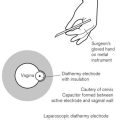
• Strong sources of electromagnetic interference, diathermy for instance, can interact with pacemakers and defibrillators.
• Consultation with a cardiac electrophysiologist or cardiac technician is essential to understand the detailed functioning of these devices and to plan the treatment of patients.
Basic cardiac electrophysiology
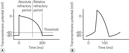
To understand pacemaker and defibrillator functioning, an understanding of normal cardiac electrophysiology is necessary. The myocardium consists of an interconnected network of myocytes. At rest, the myocyte interior is maintained at a negative potential (−80 mV) in relation to the extracellular fluid. This is due to the relative impermeability of the plasma membrane, differential intra- and extracellular ion concentrations and active ion transporters. Either because of the spontaneous inward leak of positively charged ions, in the sinus node for example, or because of an external electrical stimulus, the potential difference across the membrane decreases. At a threshold potential (approximately −70 mV in ventricular myocytes) various ion channels become activated producing further ion influx. This leads to myocyte depolarization and the action potential (Fig. 25.1). Calcium influx leads to the release of additional intracellular calcium stores activating the contractile apparatus, a process described as excitation-contraction coupling.
Pacemakers
The NASPE/BPEG code
1. VVI. A single lead is placed in the ventricle, for pacing (VVI) and sensing (VVI). If the ventricular rate is above the minimum set (the base rate), pacing is inhibited (VVI). Otherwise pacing occurs.
2. AAI. A single lead is placed in the atrium. It functions in a similar way to the VVI and is used for sick sinus syndrome where AV nodal conduction is normal.
3. DDD. Leads are present in the atrium and ventricle. Both chambers (hence dual) can be paced (DDD) and sensed (DDD). If activity in either chamber is sensed a pacing stimulus will be inhibited. If no ventricular activity follows atrial activity, ventricular pacing will be triggered (DDD representing the dual responses of inhibition or triggering).
4. VOO/AOO/DOO. These are the simplest pacing modes. No sensing occurs (_O_) and therefore there can be no response to sensing (__O); the chamber(s) is paced at a fixed rate. This mode is used temporarily where the sensing of external noise could lead to the inappropriate inhibition of pacing, e.g. diathermy. It is also known as asynchronous pacing.
5. VDD. Only one lead is used which paces the ventricle (VDD). An electrode further up the lead is positioned in the atrium allowing dual chamber sensing (VDD). This allows physiological pacing, i.e. ventricular activity follows atrial at a physiological PR interval as long as atrial pacing is unnecessary. This mode is uncommon and is used as an alternative to DDD pacing in order to reduce system complexity.
6. The presence of an (R) as the fourth letter denotes a pacemaker able to increase the paced heart rate in response to the patient’s activity (see below, Software).
Pacing terminology
A number of pacing terms require explanation:
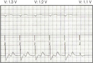
• Threshold (Fig. 25.2) – the minimum stimulus needed to capture the heart. It is given as current (amperes) or voltage (volts) over a time period (pulse width, ms).
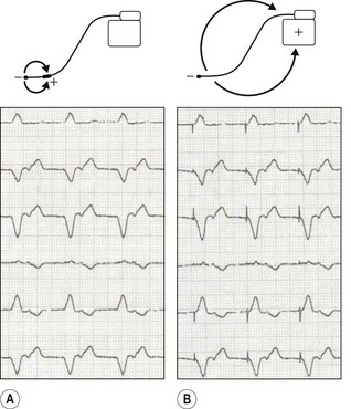
• Unipolar/bipolar – refers to the arrangement (Fig. 25.3) of the negatively charged cathode and the positively charged anode. In the bipolar circuit, the cathode and the anode are separated by a short distance at the pacing lead tip. The circuit is localized to the immediate myocardium. In the unipolar circuit, the cathode is at the pacing lead tip with the anode at a distance; in the permanent pacing system it is found in the pacing box. The unipolar pacing circuit is larger and, therefore, produces a larger pacing artefact on the ECG. While there is little difference between the pacing characteristics of these two conformations, bipolar sensing is less susceptible to external noise.
• Impedance – this represents the total resistance to current flow in the pacing circuit. This resistance occurs in the leads, at the lead–myocardial interface for endocardial leads and in the tissue between the cathode and the anode. Fractures in the leads increase impedance, while insulation breaks reduce it.
Temporary pacing
Transvenous pacing
This is the usual method for temporary pacing. A thin, semi-flexible, shaped, bipolar pacing lead is normally used. The central circulation is accessed via the internal jugular, subclavian or femoral veins, the first of these being preferable as there is a lower risk of complication (e.g. pneumothorax with the subclavian route, infection and deep vein thrombosis with the femoral). Furthermore, with the internal jugular approach, the veins used for permanent pacing are not directly punctured. The lead is manipulated into position at the right ventricular apex under X-ray guidance. Some leads may have a central shapeable stylet to allow more accurate positioning. Others have a tip-mounted flotation balloon to allow non-radiographic positioning. Active fixation (screw tipped) leads are also available to prevent lead displacement. In most cases one ventricular lead is used. Atrial pacing and dual chamber pacing are also possible. For temporary transvenous pacing, due consideration must be given to the possible need for permanent pacemaker insertion and the impact thereon of infection and local complications at vascular access. It is hence advisable to avoid the subclavian route and to use ultrasound guidance for vascular puncture. Various guidelines are listed in the bibliography section at the end of this chapter.
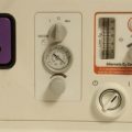
The pacing lead is connected to an external box which allows various programming options:
1. Mode: usually VVI (’demand’) or VOO (‘asynchronous’ or ‘fixed rate’)
2. Output: either the output voltage or current is programmable, the pulse width being fixed. Maximum outputs are higher than with permanent systems as battery size is unrestricted and the threshold is more unstable
3. Sensitivity: the threshold above which electrical activity will be detected as cardiac. This is usually measured in millivolts, a higher value indicating lower sensitivity
4. Rate: usually 30–150 or even higher for the overdrive pacing of tachyarrhythmias.
Transoesophageal and transgastric pacing
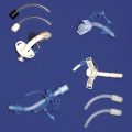
An electrode (on a device similar to an oesophageal stethoscope or nasogastric tube),1 placed in the oesophagus, can capture the left atrium, while in the stomach ventricular pacing may be possible. Transoesophageal atrial pacing (TAP) is a simple and safe method for temporary treatment of bradyarrhythmias and is particularly applicable to use during anaesthesia.2 Because voltages of up to 20V or more may be required to achieve capture (Fig. 25.2), a signal amplifier is needed if using an ordinary external (transvenous) pacing box (signal generator). TAP, like transgastric pacing, is rarely used because of unfamiliarity with the technique and scarcity of equipment.
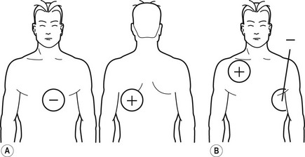
Transcutaneous pacing
In the peri-arrest situation it may be difficult to position a transvenous temporary wire. It is possible to capture the ventricle by passing a large enough current through the chest using specially designed electrodes (Fig. 25.4). These electrodes may also be used for monitoring and defibrillation.
Permanent pacing
Hardware
The pacemaker box consists of:
1. The battery. This forms a major part of the volume of the pacemaker. It has a number of important requirements including:
2. Voltage/output circuits. Various circuits are required to allow the battery voltage (usually 2.8 V at implant) to be altered to produce a range of programmable outputs, according to the threshold, to prolong battery life.
3. Telemetry circuits. These allow an external computer to communicate and programme the pacemaker using radiofrequency signals.
4. Pacing circuits. These control all aspects of pacemaker function including the timing circuits, diagnostics and the rate response circuitry.
5. Sensing circuits. These allow sensing of intrinsic cardiac activity with filtering allowing exclusion of external electromagnetic noise.
6. Memory. Modern pacemakers are able to store significant quantities of data, for example on arrhythmias and heart rate variability.
7. Reed switch. This is activated by the magnet, completing a circuit allowing a particular predefined programme to start.
1. Electrode. Most newly implanted leads are bipolar with a cathodal tip and a larger anode further back. The cathode is surprisingly complex – it is small, producing: a high charge-density, thus improving myocardial capture; and a high pacing impedance which reduces battery drain. Platinum, titanium or activated carbon is used for their good conducting properties and durability. A small reservoir of steroid is also found in the lead tip to reduce the inflammatory reaction at the lead–myocardial interface, maintaining lower stimulation thresholds.
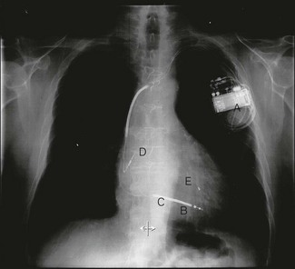
2. Fixation mechanism. It is necessary to secure the lead in the myocardium thus maintaining capture. Passive fixation is achieved with small flexible protrusions from the lead tip, tines, which hook into the trabeculated muscle. For less stable positions active fixation mechanisms are available, often a small retractable screw (Fig. 25.5D).
3. Lead conductor. This is the wire, often made of a complex alloy, which transmits the electrical current. Bipolar leads require two, one each for the cathode and the anode. Coiling the wires produces great lead flexibility, the anodal conductor being wound inside the cathode, separated by an insulator (coaxial wire). A recent advance involves coating each individual conductor with insulation (coated wire technology), which allows the anodal and cathodal conductors to run together producing leads with even smaller diameters.
4. Lead insulation. Silicon was used initially; polyurethane is used today; it allows flexibility, resistance to damage, biocompatibility and good handling characteristics.
5. Lead connector. The metal connectors which link the conductor to the pacemaker. There is now an industry standard, IS-1.
6. Central lumen. A central lumen runs the length of the lead allowing the passage of a stylet that can be shaped to allow accurate positioning. A number of leads are also shaped to allow positioning in certain positions, e.g. the coronary sinus or the right atrial appendage.
Software
1. Mode (see The NASPE/BPEG code, above)
2. Base rate – the minimum paced rate
3. Hysteresis rate – it is possible to allow the intrinsic heart rate to drop to a lower value, say 40, before pacing is initiated at a higher rate, say 60
4. Maximum paced rate – the maximum rate above which pacing will not occur, either driven by the patient’s atrial rate or by the rate sensor
5. AV delay – the paced equivalent of the PR interval
6. Rate response functions. An increase in heart rate is a prime mechanism through which cardiac output is increased during both physical and mental activity. To allow a more physiological heart rate response in paced patients with abnormal sinus node function, many pacemakers sense this requirement; motion sensors, changes in transthoracic impedance as a marker of respiratory rate and QT interval are used. The pacing response can then be tailored to each patient
7. Sensitivity. The signal amplitude above which electrical activity will be ‘seen’
8. Mode switch. Pacemakers should not track atrial tachycardias. Modern pacemakers can detect these arrhythmias and change mode accordingly.
Future directions
1. pacing to improve symptoms and prognosis in heart failure. Many patients with heart failure have conducting system abnormalities, e.g. left bundle branch block which produces dyssynchonous contraction of the right and left ventricles. Biventricular pacing (Fig. 25.5), in which both the right and left ventricle, via the coronary sinus, are paced, can restore co-ordinated ventricular activation and has been shown to improve symptoms and reduce mortality
2. pacing to prevent atrial tachyarrhythmia
3. pacing to prevent ventricular tachyarrhythmia in long QT syndrome
4. pacing to alleviate symptoms in vasovagal syncope
5. pacing to reduce the outflow gradient in hypertrophic cardiomyopathy.
Vagal nerve stimulators
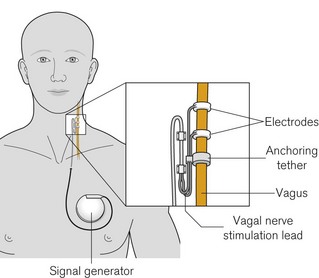
The system consists of a constant current pulse generator placed subcutaneously, as with cardiac pacemakers, in the pectoral region and connected onto the left vagus with a tunnelled lead culminating in spiral platinum electrodes embedded in silicone rubber (Fig. 25.6). The left nerve is used as the right vagus nerve carries a higher proportion of cardiac efferents. Again, as with cardiac pacemakers, subsequent programming is via an external computer with radiofrequency signals. Stimulation patterns are episodic (e.g. up to 90 s on and 5–10 min off) and patients carry a magnet whose transient application results in an additional pre-programmed burst of stimulation which may abate or prevent a seizure. The magnet can be held or fixed over the signal generator to pause stimulation, in order to limit some of the problems below.
Patients usually also carry a copy of the manufacturer’s instructions for reference.
In addition to the usual issues regarding electromagnetic interference (see later), there are a number of specific problems that are noteworthy for anaesthetists. They are mostly related to ‘on time’ of the device, when stimulation is taking place:
• Effects on heart rate and automaticity. Bradycardia appears commonplace; complete heart block and asystole are reported under anaesthesia and particularly at device insertion/activation.
• Vocal cord and laryngeal apparatus dysfunction, resulting in cough, voice alteration, swallowing difficulties and aspiration.3
• In addition to the above, effects on respiratory control (central and/or peripheral) are noted which can manifest as induced or worsened obstructive sleep apnoea.
Defibrillators
Introduction
Factors affecting DFTs include:
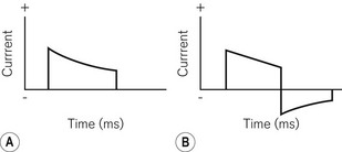
1. Charge characteristics. A monophasic shock is one where the polarity of the shock remains constant throughout its delivery (Fig. 25.7A). In biphasic shocks (Fig. 25.7B) the polarity is reversed during delivery. In general terms, DFTs are lower and there is less post-shock myocardial depression with biphasic shocks. The shape and time-course of the shock can also be varied to produce optimal effects.
2. Electrode position. In implantable systems shocks can occur in a number of configurations that may affect the DFT (see Hardware, below). Altering the position of the endocardial coils can also have some effect. External paddle positions may also have an effect.
3. Shock polarity. Which electrode is used as the anode and which the cathode can affect DFTs, particularly with monophasic shocks.
4. Underlying cardiac condition. The more severe the cardiac condition, as assessed using heart size, ejection fraction, QRS width or heart failure symptoms, the higher the DFT. Furthermore, the time spent in VF prior to defibrillation adversely affects DFTs.
5. Metabolic disturbance. DFTs are higher in hypoxic and acidotic patients.
6. Medication. DFTs can be affected by numerous medications. Of note, intravenous amiodarone reduces DFTs, whereas its chronic administration increases them. Fentanyl reduces DFTs. Common inhalational anaesthetic agents do not appear to have significant effects.
7. Shock impedance. Shock impedance affects current delivery to the myocardium. The transthoracic impedance for external defibrillation is dependent on lung volume, skin contact and tissue thickness.
The implantable cardioverter defibrillator
Hardware
The ICD system (Fig. 25.5) consists of a box containing:
1. Battery. The defibrillator battery has a number of requirements in common with pacemaker batteries:
2. Capacitor. The ICD battery is unable, by itself, to produce sufficient charge quickly enough to allow defibrillation. The charge is, therefore, built up and stored in a capacitor which is discharged when required by completing the circuit between the capacitor plates via the myocardium. Modern ICD capacitors consist of thin films of aluminium, separated by a non-conducting layer of aluminium oxide
3. Voltage/output circuits. These allow different voltages to be produced for pacing and for capacitor charging. In addition the capacitor output can be controlled to produce the biphasic shock
1. A pace/sense electrode. This is essentially identical to a normal lead for a pacemaker. The cathode is found at the tip, with the anode either separate from or integrated with the distal shocking coil.
2. One/two shocking coils. The distal lead coil is positioned in the right ventricle and the proximal coil in the superior vena cava. They are constructed of similar material to pacing electrodes, but with a large surface area to improve current delivery. It is through these coils that the charge is distributed. A number of shock pathways are possible which may produce varying DFTs. The most common is between the coils and the ICD box; it is also possible to shock between the box and one coil or between one coil and the other.
4. Lead conductor. The conductors are of similar construction to those of pacing leads. With a dual coil, bipolar defibrillator lead four are necessary – one per coil and one each for the pacing anode and cathode
6. Lead connector. An IS-1 connector is used for the pace / sense functions. An industry standard connector for the defibrillator coils, DF-1, has been defined. Standard ICD leads currently have three connections, one IS-1 and two DF-1 connectors, making them bulky. A new slimline connector incorporating all necessary connections on one lead is now available, (IS-4) and will be increasingly used.
Software
1. up to three zones for the detection and treatment of different ventricular tachyarrhythmias
2. multiple electrogram characteristics can be used to improve the sensitivity and specificity of differentiating ventricular arrhythmia from other rhythms (rate, onset characteristics, rate stability, ECG morphology, relationship of atrial to ventricular activity, etc.)
3. varying treatment options, which are programmable, including anti-tachycardia pacing, low-energy cardioversion and defibrillation
4. aspects of shock characteristics that are programmable including varying energies, shock pathways, polarity, timing, etc.
5. single, dual or biventricular pacing functions
6. in some devices, the ability to detect and treat atrial tachyarrhythmias
7. the opportunity for electrophysiological studies to be performed non-invasively.
Electromagnetic interference
1. Diathermy – this can affect pacemakers in a number of ways, as discussed above. In addition, the diathermy current can activate the rate-response circuitry, damage the pacing circuits or pass via the lead damaging the lead-myocardial interface thus affecting pacing thresholds. Bipolar pacemakers are much less susceptible to this. Suggested management includes:
2. Cardioversion/defibrillation – like diathermy, the considerable current used can overwhelm the protective circuitry and reprogramme or damage the device or the lead–myocardial interface. Management includes device interrogation pre- and post-procedure. Paddles should be placed at least 10 cm from the box and at 90° to the axis of box to lead tip (preferably AP).
3. MRI – the scanner can interact in a number of ways with pacing systems, not least because of the ferromagnetic components of old devices. Strong electrical signals are also produced that can either inhibit or induce rapid pacing. In general terms, an MRI is contraindicated in pacemaker/ICD patients, although case reports exist of patients undergoing this investigation without ill-effect. There is now an MRI-safe pacemaker available from Medtronic with the other pacing companies soon to follow suit. The model is safe to use in an MRI scanner six weeks after implant. MRI-safe ICDs are also likely to come at some point.
4. Lithotripsy – the shock can trigger an arrhythmia, cause mode switch or pacemaker inhibition or damage the box and, in particular, the piezoelectric crystals used for activity sensing. The manufacturer should be consulted particularly for abdominally placed systems, devices should be programmed to an asynchronous mode and ICDs should be disabled.
5. Radiotherapy – if directed at the pacing box this may destroy the circuitry. Pacing systems require repositioning.
6. Electroconvulsive therapy – adverse effects are unlikely, but pacemaker checks and asynchronous pacing are suggested.
1 McEneaney DJ, Cochrane DJ, Anderson JA, Adgey AA. A gastroesophageal electrode for atrial and ventricular pacing. Pacing Clin Electrophysiol. 1997;20:1815–1825.
2 Andersen HR, Pless P. Trans-esophageal pacing. Pacing Clin Electrophysiol. 1983;6:674–679.
3 Lundgren J, Ekberg O, Olsson R. Aspiration: a potential complication to vagus nerve stimulation. Epilepsia. 2005;39:998–1000.
Cummins RO, Hazinski MF, Kerber RE, Kudenchuk P, Becker L, Nichol G. Low-energy biphasic waveform defibrillation: evidence-based review applied to emergency cardiovascular care guidelines. Circulation. 1998;97:1654–1667.
Ellenbogen KA, Wilkoff BL, Kay GN, Lau CP. Clinical cardiac pacing, defibrillation and resynchronization therapy, 3rd ed. Philadelphia: WB Saunders; 2006.
Epstein AE, DiMarco JP, Ellenbogen KA, Estes NA, 3rd., Freedman RA, Gettes LS, et al. ACC/AHA/HRS 2008 guidelines for device-based therapy of cardiac rhythm abnormalities. J Am Coll Cardiol. 2008;51:e1–62.
2005 European Resuscitation Council Guidelines 2005 for Resuscitation. Resuscitation. 2005;67:S1.
Gammage MD. Temporary cardiac pacing. HEART. 2000;83:715–720.
Gold MR. Permanent pacing: new indications. HEART. 2001;86:355–360.
Hatton KW, McLarney JT, Pittman T, Fahy BG. Vagal nerve stimulation: overview and implications for anesthesiologists. Anesth Analg. 2006;103(5):1241–1249.
Murphy JJ. Problems with temporary cardiac pacing. Anesth Analg. 2001;323:527.
http://www.physiocontrol.com/learning/clinical-topics/defibrillation.aspx. Accessed on 2nd Aug 2011
http://www.physio-control.com/learning/clinical-topics/index.aspx?id=2147483878. Accessed on 2nd Aug 2011