[level-membership-for-cardiovascular-category]
Chapter 32 Pacemaker Insertion, Revision, and Extraction
Implantation
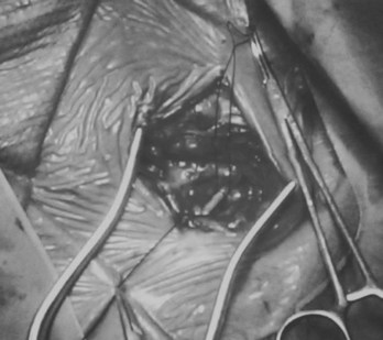
Transvenous pacing is usually the preferred route, with use of the cephalic vein, the subclavian vein, or the axillary vein; it is rare to employ the external or internal jugular veins. Identification of a reasonably sized brachial or antecubital vein by placing a tourniquet around the arm is a good predictor that the patient will have a usable cephalic vein more proximally. After meticulous preparation, draping, and administration of local anesthesia, a circumlinear incision is made; dissection follows down to the delto-pectoral fat pad, beneath which courses the cephalic vein (Figure 32-1). Many implanters choose to access the subclavian vein percutaneously before making such an incision, in the belief that the anatomies of the clavicle and the first rib are better appreciated “from the outside.” Nothing, however, precludes using the subclavian approach from within the incision if the cephalic vein is not encountered. The distinct advantages to looking for the cephalic vein first are as follows: (1) It avoids the potential risk of pneumothorax, subclavian artery puncture associated with attempts at subclavian vein puncture, or both; (2) it may avoid trauma to the lead incurred in the subclavian crush syndrome or associated with the peel-away introducer technique; (3) it provides yet another avenue of access not available to those implanters who are accustomed to only the subclavian puncture technique, and (4) in cases of subsequent revision, it allows the use of an unused subclavian vein. Ligatures are applied proximally and distally to the site of the venotomy (Figure 32-2). It is particularly important to tie off the distal ligature (usually with 3-0 silk) before introducing the lead to prevent significant back-bleeding should a small cephalic vein avulse with manipulation. Vein lifts that are typically supplied with the pacemaker electrodes can be abrasive; the author prefers to use a curved iris forceps. The lead should be visually inspected before introducing it to ensure that no defects are present at the very outset before manipulation.
Often a venotomy through the cephalic vein will accommodate both atrial and ventricular leads. Occasionally, only one (or neither) may be introduced primarily, because the vein is either too small or tortuous. In such cases, one may consider introducing a guidewire through the cephalic vein and then using a peel-away introducer technique through the cephalic vein to introduce one or both leads (Ong-Barold technique; see Figures 32-3 and 32-4). Again, great care should be taken while advancing the introducer (use of a Gerard forceps to raise the flap of the venotomy may be helpful here) to avoid avulsing the cephalic vein, and fluoroscopic visualization of the advancing introducer may be helpful to track its course along the guidewire. Percutaneous subclavian vein access has been made possible largely by the peel-away introducer technique, which allows access to be achieved through the Seldinger technique and removal of the sheath subsequently from the retained pacemaker lead. A variety of techniques has been reported. The subclavian window approach entails puncturing near the apex of the angle formed by the first rib and clavicle and aiming medially and in the cephalic direction. The medial aspect of this approach has a better success rate and a lower risk of pneumothorax and vascular injury compared with a more lateral entry because the vein is a larger target and the apex of the lung is more laterally situated. The tighter binding between the first rib and clavicle may, however, result in the subclavian crush phenomenon with insulation failure, particularly in the case of bipolar coaxial polyurethane leads. The “safe introducer technique,” as described by Byrd, relates to a safety zone between the first rib and clavicle, extending laterally from the sternum in an arc. More lateral approaches may avoid soft tissue entrapment (subclavius muscle, costocoracoid ligament, and costoclavicular ligament) and may, therefore, extend lead longevity. Cannulation of the extrathoracic portion of the subclavian vein (the axillary vein) has been increasingly used, with puncture made anteriorly to the first rib, maneuvering posteriorly and medially, but remaining lateral to the juncture of the first rib and clavicle; in the more lateral locations, care must be taken to avoid puncturing the subclavian artery. The use of radiography has been advocated during the introduction of needles, whatever may be the technique chosen, to confirm point of entry and subsequent trajectory (Figure 32-5); in some cases, dye injection with venography may facilitate venipuncture (Figure 32-6), particularly in cases where access has been difficult and the risk of subclavian vein thrombosis exists. This may be particularly effective in guiding venipuncture when using the axillary vein approach. Occasionally, Doppler techniques to facilitate vein localization and venipuncture may be used. In patients who have superior vena cava, innominate vein obstruction, or both, stent dilation has been considered to achieve access without going to the contralateral chest. Once access to the subclavian vein has been achieved, an incision must be made to allow for the development of the pocket if the puncture was percutaneous and not from within the wound. The peel-away-introducer technique then allows for passage of the introducer over the guidewire and subsequent passage of the pacemaker lead through the introducer. If the leads are small (especially if unipolar), both may be guided through a single introducer. More commonly, the guidewire is retained after passage of the first lead to allow for the passage of a second introducer and pacemaker lead, which obviates the need for a second venipuncture (Figure 32-7); alternatively, two guidewires may be passed through a single percutaneous introducer with subsequent sliding of the introducer over each guidewire separately to provide independent access for each of two pacing leads. Occasionally, a recently introduced lead may cause problems (e.g., a need to switch from a passive fixation to active fixation lead) with loss of previously established venous access. In such cases, a blade may be used to slit the insulation of the lead to be sacrificed, a guidewire wedged through this insulation, and the lead advanced with a guidewire as a unit so that the guidewire enters the vascular space. With the guidewire held in place, the lead to be sacrificed may be advanced slightly so as to disengage it from the guidewire; in this manner, the guidewire is retained within the vascular space, the old lead may be removed, and a new lead may be placed through a peel-away introducer placed over the guidewire (Figure 32-8). The technique required for lead manipulation may vary as a function of the lead used and the cardiac chamber to be accessed. For right ventricular apex positioning, one approach is to prolapse the lead across the tricuspid valve (Figure 32-9). The other commonly employed approach is to create a curve on the stylet and guide the lead to the right ventricular outflow tract, subsequently withdrawing the lead until it drops into the right ventricular apex position (Figure 32-10); this approach ensures that passage has been achieved into the right side of the heart and reduces the inadvertent placement of the lead into the coronary sinus. With any lead manipulation, great care must be undertaken to avoid dislodgment of other leads already in place, particularly if these have been recently placed. In addition, placement of the leads may result in the induction of ventricular arrhythmias and trauma to the atrioventricular node or right bundle (of great concern in patients with pre-existing left bundle branch block), dictating the need for backup equipment for external pacing and defibrillation. Placement of the ventricular lead in patients with persistent left superior vena cava may be particularly challenging. The loop-de-loop technique is used in which the lead enters the dilated coronary sinus from the left superior vena cava and is banked off the right atrial wall to re-enter the right ventricular apex. An active fixation lead is recommended for stabilization of position in this case (Figure 32-11). Occasionally patients may require placement of the lead in the right ventricular outflow tract; for example, to minimize electrical interaction with a previously implanted right ventricular apex defibrillator lead, an active fixation bipolar lead should be employed (Figure 32-12). The optimal position for right ventricular pacing to promote cardiac hemodynamics (e.g., apical versus outflow tract) is still being debated, but to date, no definitive answer has been found.
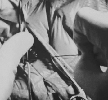
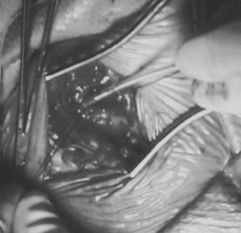
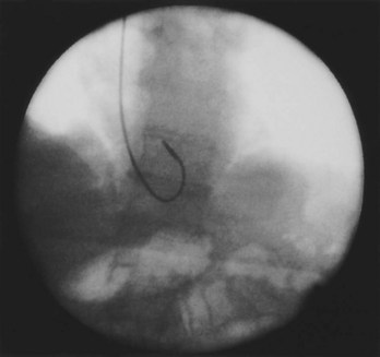
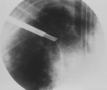
Figure 32-3 Insertion of guidewire through cephalic vein; first lead already inserted through venotomy.
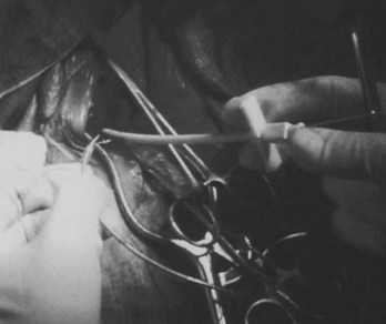
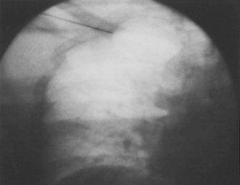
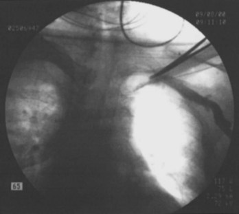
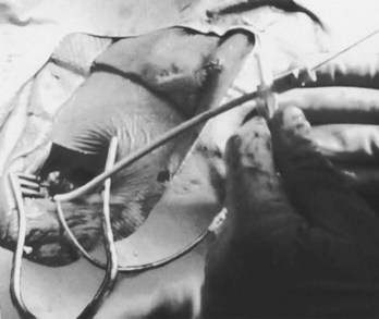
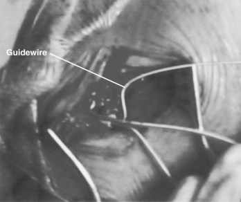
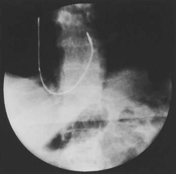
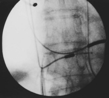
Figure 32-8 Insertion of guidewire under insulation of lead to be sacrificed, to re-establish venous access.
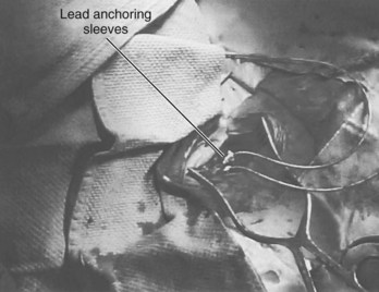
Perhaps the most important step in pacemaker implantation is lead anchoring. An anchoring sleeve minimizes trauma by being sutured (typically a 0-silk) to the underlying lead insulation, conductor, or both (Figure 32-13). The right balance must be achieved between anchoring the sleeve too securely and anchoring it not securely enough; it is easier to bury the sleeves with a purse-string suture with leads implanted via the cephalic route than via the subclavian route. In addition, repeat fluoroscopy should be undertaken once anchoring has been performed to make sure that lead position, redundancy, or both remain stable at baseline as well as with deep breathing. Enough slack should be provided to accommodate tall individuals, particularly those with large respiratory excursions, to prevent undue tension or retraction of the lead. The leads are then connected to the connector block of the generator; it is critical to ensure that the set screw sites are adequately tightened (including both poles in the case of bipolar leads) by gentle tugging on the lead. Application of sterile adhesive over the set screw site may minimize current drain through this locale.
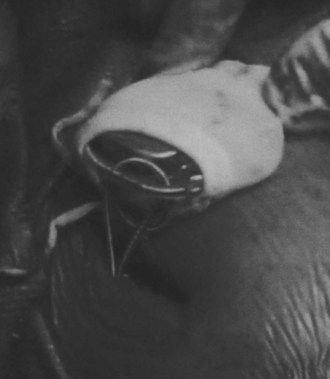
Creation of the generator pocket, either with Metzenbaum scissors or forceps or blunt finger dissection, is followed by placement of the generator inside the pocket. It is useful to irrigate the pocket with antibiotic solution. Hemostatic thrombin-containing preparations, absorbable meshes, or both may sometimes be instilled or left within the pocket. Any redundant or excess lead should be placed under the can so that future generator replacements will not be compromised by inadvertent slicing of the lead(s). In some cases, placement of the generator and lead within a Dacron pouch (“Parsonnet pouch”) (Figure 32-14) may allow for more ideal stabilization and anchoring of the system in the prepectoral fat and thereby minimize generator migration and extrusion, or the so-called twiddler’s syndrome. In some patients, a submammary generator placement may be considered for cosmetic reasons; the lead electrodes may be tunneled from the infraclavicular site of entry to the inframammary incision by using a long needle, a guidewire, and an introducer/dilator technique similar to the retained guidewire technique described earlier (Figure 32-15). After insertion of the generator into the pocket, fluoroscopic confirmation of lead stability is important to rule out lead retraction during this process. Potential complications associated with pacemaker implantation are numerous but fortunately uncommon and have been well described elsewhere. A clear inverse relationship exists between operator experience and complication rate; a direct relationship is associated with the use of subclavian puncture. Preparedness for any eventuality, as discussed previously, remains an important goal. Although problems with bleeding are usually readily apparent, as in complications due to arrhythmia induction, the two most worrisome issues likely to be encountered are sudden hypoxemia and hypotension, which may occur independently or together. The former raises the possibility of pneumothorax, oversedation, or air embolism (when the introducer technique is employed), whereas the latter may include a variety of issues such as ongoing bleeding (suspected or otherwise), hypovolemia, medication, left ventricular dysfunction, pneumothorax, or cardiac tamponade. Some of these complications may lead to a vicious downward spiral; it is, therefore, incumbent on the implanter to keep close scrutiny on the vital signs, oximetry, and rhythm and remain in constant communication with the other team members in the operating arena who are monitoring these factors.
Pacemaker Upgrades, Revisions, and Generator Replacements
If subclavian vein thrombosis is present or the infraclavicular space is too tight to accommodate a second lead (even the smallest unipolar available), then access may be attempted via the contralateral chest with tunneling of the new lead under the skin to the original pacer site (Figure 32-16). The alternative would be to abandon the original site altogether and place a new dual-chamber system via the contralateral chest. If the new lead is to be implanted and tunneled back, a smaller incision can be used; once again, anchoring is of vital importance. For tunneling, a Kelly clamp can be advanced bluntly in the subcutaneous tissue from the receiving (original) site to the satellite (contralateral) site. The free terminal end of the new atrial lead may be placed through a Penrose drain with a gentle tie applied around the drain just distal to the lead connector. The free end of the Penrose drain is then grasped and pulled through the tunnel, back to the original implantation site; the tie is released and the drain is then removed. Alternative approaches include the use of a guidewire and the peel-away introducer technique (introduced from the original site to the satellite location), with passage of the terminal end of the new lead back through the sheath to the original site; a chest tube may also serve as the tunneling conduit. Great care must be taken to strive for a tunnel that is deep (as close as possible to the overlying muscle) and to avoid traumatizing the lead during the tunneling process.
Management of Pocket Hematoma, Erosion, Infection, and Pacer Extraction
Improved fixation techniques used to minimize lead dislodgment have ironically led to increased difficulty with lead extraction when required. As a result, countertraction and counterpressure techniques and devices have been developed to facilitate extraction. The use of locking stylets has made it far easier to apply direct traction. The superior lead extraction approach entails opening the pocket and using lead clippers to remove the terminal connector from the pacer lead to be extracted. The insulators and outer conductor coil (in the case of coaxial leads) are trimmed back to expose the inner conductor coil, and the opening of this coil is then broadened with a coil expander. Sizing of the inner conductor coil is then undertaken, typically with a set of variably sized gauge pins, to select the largest locking stylet that will fully enter the inner conductor coil. The locking stylet is then introduced and advanced to the lead tip. In some stylets, counterclockwise rotation may be required (Cook Vascular, Leechburg, PA), whereas in others (Wilkoff stylet, Cook Vascular), removal of a latch pin and pushing of the locking cannula forward are required to activate the locking mechanism. In yet another model (Spectranetics, Colorado Springs, CO), a lead-locking device stylet has a fine, wire mesh stretched over its entire length; the mesh is released once the stylet is advanced and by bunching up holds the lead along its entire length (Figure 32-17). Tugging on the stylet to ensure the adequacy of locking is followed by ligating the end of the lead insulation with 2.0 suture and tying the suture ends to the locking stylet loop handle. This handle is flattened and placed through a preselected sheath set (telescoping inner and outer sheaths).
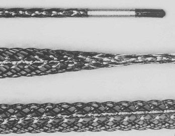
Figure 32-17 Special mesh locking stylet that expands along the entire length of the lead to be extracted.
Standard sheaths are made of a plastic, such as Teflon (E.I. DuPont, Wilmington, DE) or stainless steel. The latter are used typically during initial entry into the central venous circulation and are used to cut through dense fibrosis near the subclavian site; then they are exchanged with the more flexible plastic sheaths that are used to negotiate through the various curves encountered along the venous path. Continuous and moderate tension is applied on the locking stylet as first the metal set and then the plastic sheaths are advanced to disrupt the fibrotic deposits (the outer sheath has a sharp cutting edge that is advanced over its inner sheath). Fluoroscopic guidance is deemed essential, on the basis of the recognition that misdirected dilators may result in serious vascular injury, particularly at curvatures in the vein where the more flexible plastic sheaths are required (Figure 32-18). If too much tension is applied to the lead–locking stylet combination, the same risks associated with conventional external traction may arise: tearing the lead, avulsing the vein or heart wall, or disengaging the locking stylet from the lead. The larger sheath is advanced over the inner sheath, while the smaller sheath is always kept on the leading edge in a telescoping forward movement. A snow plow effect may arise with scar tissue that is peeled away from the venous wall and pushed in front of the sheaths, thereby preventing further advancement of the dilators. When the sheath set approaches the lead tip near the tissue–electrode interface, the outer sheath is removed and reversed so that its blunt end faces the myocardium and countertraction is then applied against the myocardial surface to release the lead tip. In some cases, after a chronic (noninfected) lead is removed, the retained sheath may be used to place a guidewire and then a peel-away dilating sheath is used to guide the placement of the new pacemaker lead; occasionally, balloon venoplasty may be required as an adjunct.
Powered sheaths have been developed to reduce the need for traction and counterpressure. The laser sheath is used to deliver excimer laser energy fiberoptically to the distal end of the sheath to dissolve the encapsulating fibrotic tissue in circumferential fashion (Figure 32-19). The laser has a very short depth of penetration, affecting only tissue that is in direct contact with the end of the sheath. This releases the lead from its tissue attachments, thus facilitating advancement of the sheath over the lead. An electrosurgical dissection sheath using radiofrequency energy with a more directed sheath tip is currently under active investigation.

Snares may be employed to apply indirect traction in extracting lead(s) by using a femoral approach. The snare device is used to encircle the free tip of the pacing lead or a loop of the lead, with traction then applied from below (Figures 32-20 and 32-21). The approach may be challenging because it is often difficult to ensnare a lead, but it may be less injurious because the coring out of surrounding fibrotic tissue is not required in this approach; nonetheless, the operator must be aware of the associated risks, femoral vein injury and thromboembolism, as well as the same potential complications associated with traction of the lead from above. The technique is indicated (1) if the lead to be extracted is not accessible from the venous entry site, (2) if the lead has been cut or fractured, or (3) if there has been retraction of the lead into the central venous circulation, intracardiac space, or both. The author’s group found the technique to be particularly well suited to removing atrial leads under the Accufix advisory associated with fracture of the inner retention J-shaped wire, particularly if this wire is protruding. If the lead is still anchored in the pectoral region, it must first be freed. Thereafter, a sheath with a hemostatic valve is placed via the femoral vein to the inferior vena cava level just below the atrium, and through this the grasping tool is deployed. Tools available for this include a deflecting tip guidewire and Dotter helical basket retriever, pigtail catheter, or Amplatz catheter; special countertraction sheaths are also available.
Acknowledgment
Byrd CL. Safe introducer technique for pacemaker lead implantation. Pacing Clin Electrophysiol. 1992;15:262.
Costeas XF, Schoenfeld MH. Undersensing as a consequence of lead incompatibility: Case report and a plea for universality. Pacing Clin Electrophysiol. 1991;14:1681-1683.
DaCosta A, Kirkorian G, Cucherat M, et al. Antibiotic prophylaxis for permanent pacemaker implantation: A meta-analysis. Circulation. 1998;97:1796-1801.
Epstein AE, DiMarco JP, Ellenbogen KA, et al. ACC/AHA/HRS 2008 guidelines for device-based therapy of cardiac rhythm abnormalities: Executive summary. Circulation. 2008;117:2820-2840.
Fearnot NE, Smith HJ, Goode LB, et al. Intravascular lead extraction using locking stylets, sheaths, and other techniques. Pacing Clin Electrophysiol. 1990;13:1864-1870.
Goldstein DJ, Losquadro W, Spotnitz HM. Outpatient pacemaker procedures in orally anticoagulated patients. Pacing Clin Electrophysiol. 1998;21:1730-1734.
Hayes DL, Naccarelli GV, Furman S, et al. NASPE training requirements for cardiac implantable electrical devices: Selection, implantation, and follow-up. Pacing Clin Electrophysiol. 2003;26:1556-1562.
Hildick-Smith D, Lowe M, Newell SA, et al. Ventricular pacemaker upgrade: Experience, complications, and recommendations. Heart. 1998;79:383-387.
Kalinchak D, Schoenfeld MH. Cardiac resynchronization: A brief synopsis Part II: Implant and follow-up methodology. J Interven Cardiac Electrophysiol. 2003;9:163-166.
Love CJ, Wilkoff BL, Byrd CL, et al. Recommendations for extraction of chronically implanted transvenous pacing and defibrillator leads: Indications, facilities, training. North American Society of Pacing and Electrophysiology Lead Extraction Conference Faculty. Pacing Clin Electrophysiol. 2000;23:544-551.
Parsonnet V, Bernstein AD, Lindsay B. Pacemaker-implantation complication rates: An analysis of some contributing factors. J Am Coll Cardiol. 1989;13:917-921.
Parsonnet V, Roelke M. The cephalic vein cutdown versus subclavian puncture for pacemaker/ICD lead implantation. Pacing Clin Electrophysiol. 1999;22:695-697.
Ramza BM, Rosenthal L, Hui R, et al. Safety and effectiveness of placement of pacemaker and defibrillator leads in the axillary vein guided by contrast venography. Am J Cardiol. 1997;80:892-896.
Roelke M, Jackson G, Harthorne JW. Submammary pacemaker implantation: A unique tunneling technique. Pacing Clin Electrophysiol. 1994;17:1793-1796.
Schoenfeld MH. Contemporary pacemaker and defibrillator device therapy: Challenges confronting the general cardiologist. Circulation. 2007;115:638-653.
Schoenfeld MH. The “natural” history of implantable defibrillators under advisory. Heart Rhythm. 2008;5(12):1682-1684. Epub 2008 October 11, 2008
Wilkoff BL, Byrd CL, Love CJ, et al. Pacemaker lead extraction with the laser sheath: Results of the pacing lead extraction with the excimer sheath (PLEXES) trial. J Am Coll Cardiol. 1999;33:1671-1676.
Zerbe F, Bornakowski J, Sarnowski W. Pacemaker electrode implantation in patients with persistent left superior vena cava. Br Heart J. 1992;67:65-66.
[/level-membership-for-cardiovascular-category][not-level-membership-for-cardiovascular-category]
Chapter 32 Pacemaker Insertion, Revision, and Extraction
Implantation
Transvenous pacing is usually the preferred route, with use of the cephalic vein, the subclavian vein, or the axillary vein; it is rare to employ the external or internal jugular veins. Identification of a reasonably sized brachial or antecubital vein by placing a tourniquet around the arm is a good predictor that the patient will have a usable cephalic vein more proximally. After meticulous preparation, draping, and administration of local anesthesia, a circumlinear incision is made; dissection follows down to the delto-pectoral fat pad, beneath which courses the cephalic vein (Figure 32-1). Many implanters choose to access the subclavian vein percutaneously before making such an incision, in the belief that the anatomies of the clavicle and the first rib are better appreciated “from the outside.” Nothing, however, precludes using the subclavian approach from within the incision if the cephalic vein is not encountered. The distinct advantages to looking for the cephalic vein first are as follows: (1) It avoids the potential risk of pneumothorax, subclavian artery puncture associated with attempts at subclavian vein puncture, or both; (2) it may avoid trauma to the lead incurred in the subclavian crush syndrome or associated with the peel-away introducer technique; (3) it provides yet another avenue of access not available to those implanters who are accustomed to only the subclavian puncture technique, and (4) in cases of subsequent revision, it allows the use of an unused subclavian vein. Ligatures are applied proximally and distally to the site of the venotomy (Figure 32-2). It is particularly important to tie off the distal ligature (usually with 3-0 silk) before introducing the lead to prevent significant back-bleeding should a small cephalic vein avulse with manipulation. Vein lifts that are typically supplied with the pacemaker electrodes can be abrasive; the author prefers to use a curved iris forceps. The lead should be visually inspected before introducing it to ensure that no defects are present at the very outset before manipulation.
Often a venotomy through the cephalic vein will accommodate both atrial and ventricular leads. Occasionally, only one (or neither) may be introduced primarily, because the vein is either too small or tortuous. In such cases, one may consider introducing a guidewire through the cephalic vein and then using a peel-away introducer technique through the cephalic vein to introduce one or both leads (Ong-Barold technique; see Figures 32-3 and 32-4). Again, great care should be taken while advancing the introducer (use of a Gerard forceps to raise the flap of the venotomy may be helpful here) to avoid avulsing the cephalic vein, and fluoroscopic visualization of the advancing introducer may be helpful to track its course along the guidewire. Percutaneous subclavian vein access has been made possible largely by the peel-away introducer technique, which allows access to be achieved through the Seldinger technique and removal of the sheath subsequently from the retained pacemaker lead. A variety of techniques has been reported. The subclavian window approach entails puncturing near the apex of the angle formed by the first rib and clavicle and aiming medially and in the cephalic direction. The medial aspect of this approach has a better success rate and a lower risk of pneumothorax and vascular injury compared with a more lateral entry because the vein is a larger target and the apex of the lung is more laterally situated. The tighter binding between the first rib and clavicle may, however, result in the subclavian crush phenomenon with insulation failure, particularly in the case of bipolar coaxial polyurethane leads. The “safe introducer technique,” as described by Byrd, relates to a safety zone between the first rib and clavicle, extending laterally from the sternum in an arc. More lateral approaches may avoid soft tissue entrapment (subclavius muscle, costocoracoid ligament, and costoclavicular ligament) and may, therefore, extend lead longevity. Cannulation of the extrathoracic portion of the subclavian vein (the axillary vein) has been increasingly used, with puncture made anteriorly to the first rib, maneuvering posteriorly and medially, but remaining lateral to the juncture of the first rib and clavicle; in the more lateral locations, care must be taken to avoid puncturing the subclavian artery. The use of radiography has been advocated during the introduction of needles, whatever may be the technique chosen, to confirm point of entry and subsequent trajectory (Figure 32-5); in some cases, dye injection with venography may facilitate venipuncture (Figure 32-6), particularly in cases where access has been difficult and the risk of subclavian vein thrombosis exists. This may be particularly effective in guiding venipuncture when using the axillary vein approach. Occasionally, Doppler techniques to facilitate vein localization and venipuncture may be used. In patients who have superior vena cava, innominate vein obstruction, or both, stent dilation has been considered to achieve access without going to the contralateral chest. Once access to the subclavian vein has been achieved, an incision must be made to allow for the development of the pocket if the puncture was percutaneous and not from within the wound. The peel-away-introducer technique then allows for passage of the introducer over the guidewire and subsequent passage of the pacemaker lead through the introducer. If the leads are small (especially if unipolar), both may be guided through a single introducer. More commonly, the guidewire is retained after passage of the first lead to allow for the passage of a second introducer and pacemaker lead, which obviates the need for a second venipuncture (Figure 32-7); alternatively, two guidewires may be passed through a single percutaneous introducer with subsequent sliding of the introducer over each guidewire separately to provide independent access for each of two pacing leads. Occasionally, a recently introduced lead may cause problems (e.g., a need to switch from a passive fixation to active fixation lead) with loss of previously established venous access. In such cases, a blade may be used to slit the insulation of the lead to be sacrificed, a guidewire wedged through this insulation, and the lead advanced with a guidewire as a unit so that the guidewire enters the vascular space. With the guidewire held in place, the lead to be sacrificed may be advanced slightly so as to disengage it from the guidewire; in this manner, the guidewire is retained within the vascular space, the old lead may be removed, and a new lead may be placed through a peel-away introducer placed over the guidewire (Figure 32-8). The technique required for lead manipulation may vary as a function of the lead used and the cardiac chamber to be accessed. For right ventricular apex positioning, one approach is to prolapse the lead across the tricuspid valve (Figure 32-9). The other commonly employed approach is to create a curve on the stylet and guide the lead to the right ventricular outflow tract, subsequently withdrawing the lead until it drops into the right ventricular apex position (Figure 32-10); this approach ensures that passage has been achieved into the right side of the heart and reduces the inadvertent placement of the lead into the coronary sinus. With any lead manipulation, great care must be undertaken to avoid dislodgment of other leads already in place, particularly if these have been recently placed. In addition, placement of the leads may result in the induction of ventricular arrhythmias and trauma to the atrioventricular node or right bundle (of great concern in patients with pre-existing left bundle branch block), dictating the need for backup equipment for external pacing and defibrillation. Placement of the ventricular lead in patients with persistent left superior vena cava may be particularly challenging. The loop-de-loop technique is used in which the lead enters the dilated coronary sinus from the left superior vena cava and is banked off the right atrial wall to re-enter the right ventricular apex. An active fixation lead is recommended for stabilization of position in this case (Figure 32-11). Occasionally patients may require placement of the lead in the right ventricular outflow tract; for example, to minimize electrical interaction with a previously implanted right ventricular apex defibrillator lead, an active fixation bipolar lead should be employed (Figure 32-12). The optimal position for right ventricular pacing to promote cardiac hemodynamics (e.g., apical versus outflow tract) is still being debated, but to date, no definitive answer has been found.
Figure 32-3 Insertion of guidewire through cephalic vein; first lead already inserted through venotomy.
Figure 32-8 Insertion of guidewire under insulation of lead to be sacrificed, to re-establish venous access.
[/not-level-membership-for-cardiovascular-category]
