6 Oxygen and Medical Gas Therapy
Note 1: This book is written to cover every item listed as testable on the Entry Level Examination (ELE), Written Registry Examination (WRE), and Clinical Simulation Examination (CSE).
The listed code for each item is taken from the National Board for Respiratory Care (NBRC) Summary Content Outline for CRT (Certified Respiratory Therapist) and Written RRT (Registered Respiratory Therapist) Examinations (http://evolve.elsevier.com/Sills/resptherapist/). For example, if an item is testable on both the ELE and the WRE, it will simply be shown as: (Code: …). If an item is testable only on the ELE, it will be shown as: (ELE code: …). If an item is testable only on the WRE, it will be shown as: (WRE code: …).
MODULE A
1. Oxygen administration
a. Recommend changes in the patient’s position to minimize hypoxemia (Code: IIIG2a) [Difficulty: ELE: R, Ap; WRE: An]
b. Position the patient to minimize hypoxemia (Code: IIID8) [Difficulty: ELE: R, Ap; WRE: An]
c. Administer oxygen to achieve adequate respiratory support (ELE code: IIID6) [Difficulty: ELE: R, Ap, An]
Oxygen (O2) must be administered in doses (up to 100%) that are adequate to treat hypoxemia, decrease the patient’s work of breathing, or decrease the work of the heart. Because the U.S. Food and Drug Administration has declared supplemental oxygen to be a drug, a physician’s order is required to give it to a patient or to make a change in the percentage. The only exceptions are when recognized protocols exist in your institution to give oxygen under certain limited conditions. For example, all patients with a diagnosed heart attack are given a nasal cannula at 2 L/min, or all patients undergoing cardiopulmonary resuscitation (CPR) receive 100% oxygen.
See Chapter 3 (Module A) for a listing of indications for drawing blood for an arterial blood gas (ABG) measurement. This list should be fairly complete for conditions that justify the need for supplemental oxygen. In general, the goal of giving supplemental oxygen is to keep the patient’s Pao2 level between 60 and 100 torr. Exceptions include carbon monoxide poisoning, severe anemia, and CPR, when the hope is to fully saturate the hemoglobin and increase the plasma oxygen content as much as possible. Oxygen should not be given without proof of hypoxemia or another clinical justification. When those conditions have been corrected, the oxygen percentage should be adjusted accordingly.
4. Central nervous system abnormalities
A patient who is breathing 100% oxygen in a hyperbaric chamber can have muscle tremors and seizures.
d. Measure the patient’s oxygen percentage, oxygen liter flow, or both (ELE code: IIIE10) [Difficulty: ELE: R, Ap, An]
Always measure the patient’s inspired O2 percentage (Fio2) if possible. The gas sample should be taken as close as possible to the patient to minimize the chance of dilution from room air. Record the oxygen percentage on the ABG order slip, in the department records, and in the patient’s chart if needed. As discussed in Chapter 3, the oxygen percentage must be known before the patient’s Pao2 level can be interpreted.
2. Manipulate oxygen and specialty gas analyzers by order or protocol (Code: IIA26) [Difficulty: ELE: R, Ap; WRE: An]
c. Troubleshoot any problems with the equipment
MODULE B
1. Manipulate oxygen and other gas cylinders, bulk storage systems, and manifolds, by order or protocol (ELE code: IIA9a) [Difficulty: ELE: R, Ap, An]
c. Troubleshoot any problems with the equipment
1. Oxygen and other gas cylinders
The different types of gases in cylinders are identified by the color code of the cylinder and the cylinder label. Note that only E cylinders have mandatory color coding. Color codings on the other cylinders are voluntary but usually are followed by the manufacturers. However, always read the label to be sure of the contents of the cylinder. The most important cylinder colors to remember are those of oxygen and air, but all are included in Table 6-1 for the sake of completeness.
| Gas | Color |
|---|---|
| Oxygen | Green (white for international) |
| Air | Yellow |
| Helium | Brown |
| Helium and oxygen | Brown and green (check the label for the percentage of each gas) |
| Carbon dioxide | Gray |
| Carbon dioxide | Gray and green (check the label for oxygen and the percentage of each gas) |
| Nitrous oxide | Light blue |
| Cyclopropane | Orange |
| Ethylene | Red |
To review how to calculate the duration of flow for a particular type of cylinder, see Table 6-2 for the cylinder duration factors, the following equation, and the following examples.
| Cylinder Size | Factor, L/psig |
|---|---|
| E | 0.28 |
| H | 3.14 |
| K | 3.14 |
| D | 0.16 |
| M | 1.36 |
| G | 2.41 |
psig, Pounds per square inch gauge.

2. Manipulate adjunct hardware, such as reducing valves, flowmeters, regulators, and high-pressure hose connectors, by order or protocol (ELE code: IIA9a) [Difficulty: R, Ap, An]
c. Troubleshoot any problems with the equipment
1. Reducing valves
Reducing valves are used to reduce the high pressure seen in a bulk oxygen storage system, manifold, or gas cylinder. One or more stages (pressure-reducing steps) can be used to reach the working pressure of 50 psig. Single-stage reducing valves reach the pressure in a single step. Multiple-stage reducing valves give finer control over pressure and flow by decreasing pressure in the first stage to about 200 psig and to 50 psig in the second stage. Occasionally, three stages are seen. All reducing valves (and regulators [combined reducing valve and flowmeter]) have the following built-in safety features:
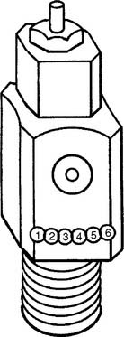
Figure 6-1 Locations of the Pin Index Safety System holes in the cylinder valve face.
(Modified from Branson RD, Hess DR, Chatburn RL: Respiratory care equipment, ed 2, Philadelphia, 1999, Lippincott Williams & Wilkins.)
TABLE 6-3 Pin Index Safety System Gases and Pinhole Locations
| Gas | Pinhole Locations |
|---|---|
| Oxygen | 2-5 |
| Air | 1-5 |
| Oxygen/carbon dioxide (≤7%) | 2-6 |
| Oxygen/carbon dioxide (>7%) | 1-6 |
| Oxygen/helium (not >80% helium) | 2-4 |
| Oxygen/helium (helium >80%) | 4-6 |
| Nitrous oxide | 3-5 |
| Ethylene | 1-3 |
| Cyclopropane | 3-6 |
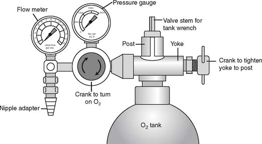
It is necessary to “crack” or blow some gas out of a cylinder before putting any reducing valve or regulator onto the cylinder. Do this by attaching the tank wrench to the valve stem and slowly turning the valve stem in a counterclockwise (so-called “lefty-loosy”) direction to release some gas. This cracking is done to prevent any dust or debris from being forced into the reducing valve or regulator, which might cause a fire. See Figure 6-2 for a schematic drawing of an “E” tank of oxygen and how its yoke is connected. If the O-ring is missing or the yoke is misaligned on the post, a high-pressure gas leak will occur when the tank is opened with the tank wrench. Close off the tank to stop the leak by turning the tank wrench on the valve stem in a clockwise direction (so-called “righty-tighty”). Investigate the yoke-to-post connection to identify causes of the leak.
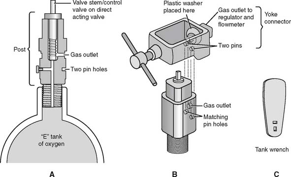
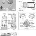
Figure 6-2 Details of an “E” size tank of oxygen and its yoke connector. A, A cross section through the stem (also called the control valve) of the tank shows its key features. B, A three-dimensional view shows how the yoke with its two pins aligns with the corresponding pin holes (locations 2 and 5) on the yoke. The plastic washer ensures a seal between the gas outlet on the stem and the yoke. (Not shown is the regulator that attaches to the yoke. See Figure 6-9.) C, A tank wrench that is attached to the valve stem (also called a control valve). Turn the wrench in a counterclockwise direction to open the tank and allow gas flow; close the tank to stop gas flow by turning the wrench in a clockwise direction.
(Redrawn from Sills JR: Respiratory care for the health care provider, Albany, 1998, Delmar Publishers.)
2. Flowmeters
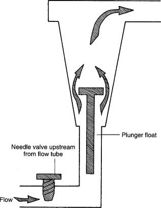
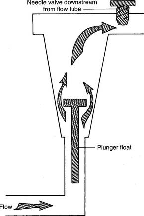
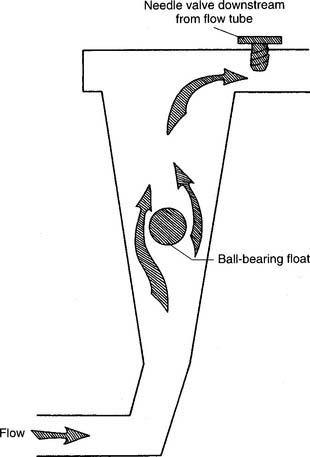
Figure 6-3 Kinetic-type non–backpressure-compensated (pressure-uncompensated) flowmeter.
(Modified from McPherson SP: Respiratory care equipment, ed 4, St Louis, 1990, Mosby.)
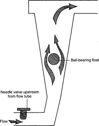
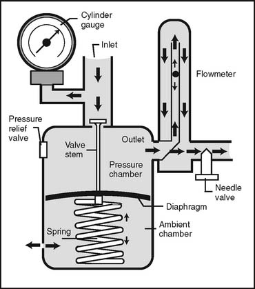
Figure 6-4 Thorpe-type non–backpressure-compensated (pressure-uncompensated) flowmeter.
(Modified from McPherson SP: Respiratory care equipment, ed 4, St Louis, 1990, Mosby.)
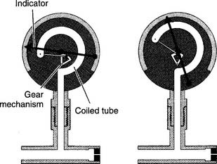
Figure 6-5 Bourdon-type non–backpressure-compensated (pressure-uncompensated) flowmeter.
(From McPherson SP: Respiratory care equipment, ed 4, St Louis, 1990, Mosby.)
d. Perform quality control procedures for flowmeters (Code: IIC6) [Difficulty: ELE: R, Ap; WRE: An]
1. Regulators
Regulators combine a reducing valve and a flowmeter (Figure 6-8). Everything that has been discussed so far relates to regulators. Bourdon gauge reducing valves usually are seen and can have a second Bourdon gauge added as a flowmeter (Figure 6-9) or a Thorpe or kinetic flowmeter. As mentioned earlier, use a backpressure-compensated flowmeter in all situations except for patient transport.
3. Manipulate pulse-dose oxygen-conserving devices by order or protocol (ELE code: IIA9b) [Difficulty: R, Ap, An]
a. Get the necessary equipment for the procedure
b. Put the equipment together and make sure that it works properly
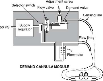
With a pulse-dose system, the proximal end of a special nasal cannula is attached to a pressure sensor on the pulse-dose system. It senses a decrease in pressure as the patient inspires. The sensor then opens a demand valve that delivers a burst of oxygen to the cannula. See Figure 6-10. Because the nasal cannula is directly attached to the pressure sensor, a bubble-type humidifier cannot be added into the system.
c. Troubleshoot any problems with the equipment
If the patient cannot feel any oxygen flowing, the following should be considered: (1) the source of oxygen might be empty, (2) the tubing might be disconnected or kinked, or (3) the sensor may not be detecting the patient’s effort. The patient or therapist can switch to a second oxygen source and look for disconnections or kinks in the tubing. The therapist must adjust the nasal cannula or sensor to correct for a sensitivity problem. Do not use a system that is malfunctioning and cannot be adjusted.
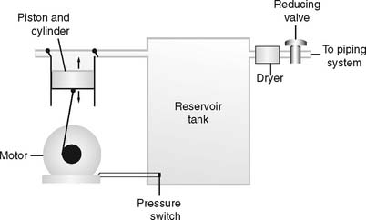
4. Manipulate air compressors by order or protocol (Code: IIA9f) [Difficulty: ELE: R, Ap; WRE: An]
c. Troubleshoot any problems with the equipment
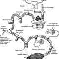
Air compressors are used whenever a high-pressure gas source other than oxygen is needed. All three systems are alike in that they use an electrically powered motor, filter the room air as it enters and exits the compressor, and have a condenser to remove water vapor as it leaves the compressor. See Figure 6-11.
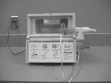
1. Rotary-type compressors
Rotary-type compressors generate pressure with a rotating fan. They are used commonly in volume ventilators and in the home to power hand-held medication nebulizers. (See Figure 6-12.)
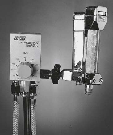
5. Manipulate air/oxygen proportioners (blenders) by order or protocol (ELE code: IIA9a) [Difficulty: ELE: R, Ap, An]
a. Get the necessary equipment for the procedure
Oxygen blenders are designed to change the ratio of oxygen and air to blend the specific percentage of oxygen from 21% to 100% (Figure 6-13). They are used whenever high-pressure gas is needed and the oxygen percentage may need frequent adjustment.
6. Manipulate oxygen concentrators (Code: IIA9c) [Difficulty: ELE: R, Ap; WRE: An] and portable oxygen concentrators (WRE code: IIA9e) [Difficulty: WRE: R, Ap, An] by order or protocol
a. Get the necessary equipment for the procedure
1. Molecular sieve
Molecular sieve–type oxygen concentrators use an air compressor to push room air through two canisters of zeolite pellets (inorganic sodium-aluminum silicate) to remove nitrogen and water vapor. The remaining oxygen is delivered to the patient through a flowmeter (Figure 6-14). Be aware that with this unit, the oxygen percentage varies inversely with the flow that is delivered (Table 6-4).

TABLE 6-4 Comparison of Flow Rates and Oxygen Percentages in Oxygen Concentrators
| Flow, L/min | Approximate Oxygen Percentage |
|---|---|
| MOLECULAR SIEVE CONCENTRATOR | |
| 1-2 | 95%-92% |
| 3-5 | 92%-85% |
| >6 | <85% |
| SEMIPERMEABLE MEMBRANE CONCENTRATOR | |
| 1-10 | 40% |
2. Semipermeable plastic membrane
Semipermeable plastic membrane oxygen concentrators make use of a very thin plastic membrane as a filter. Room air is pulled through it by a vacuum pump. Molecular oxygen and water vapor can pass through the membrane faster than nitrogen. Any excess water vapor is removed by a simple condenser system. No need exists to add an external humidification system to the flowmeter (Figure 6-15). The oxygen percentage is fixed at 40% in these units; however, the flow can be varied from 1 to 10 L/min, as shown in Table 6-4.
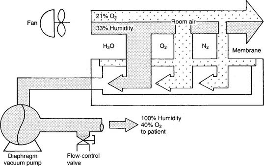
When one is deciding which type of concentrator to use, it is important to know the patient’s required oxygen percentage and flow. As can be seen from Table 6-4, the molecular sieve units can deliver a higher oxygen percentage at any liter flow as compared with the semipermeable plastic membrane units.
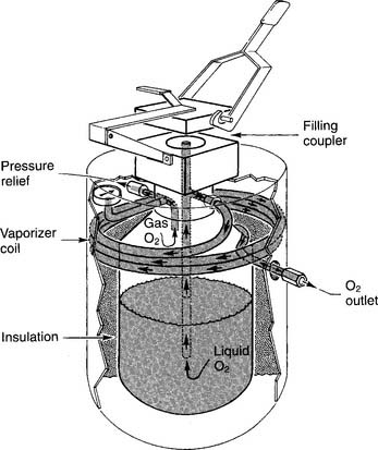
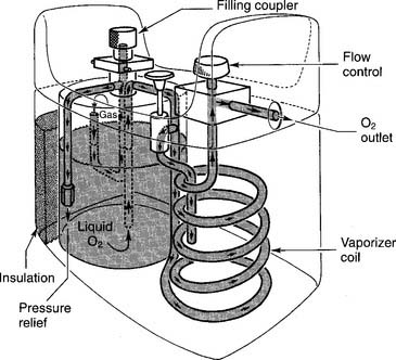
7. Manipulate portable liquid oxygen systems by order or protocol (WRE code: IIA9d) [Difficulty: WRE: R, Ap, An]
a. Get the necessary equipment for the procedure
A LOX system is used in the home when it is found to be more cost-effective than an oxygen concentrator or a battery of oxygen cylinders. An additional advantage is that the patient can carry a smaller portable unit in a shoulder bag for added mobility. Carrying it is less conspicuous than wheeling an E cylinder about. An early, widely known liquid oxygen system was the Linde Walker System (Union Carbide, Houston, TX). Figure 6-16 shows the key features of a large liquid oxygen reservoir that is kept in the patient’s home. Figure 6-17 shows its smaller portable companion, which can be filled from the large reservoir.
b. Put the equipment together and make sure that it works properly
8. Manipulate helium/oxygen equipment by order or protocol (WRE code: IIA15) [Difficulty: WRE: R, Ap, An]
a. Get the necessary equipment for the procedure
Various heliox gas mixtures come in high-pressure cylinders and require the use of an American Standard System reducing valve (or regulator) designed specifically for the gas or gas mix. As is shown in Table 6-3 and Figure 6-1, a reducing valve or regulator for an E cylinder must match the appropriate pinholes on the cylinder valve face. Corresponding high-pressure hoses also may be needed. Table 6-1 shows the color codes for the various gas cylinders. Pure helium comes in a brown cylinder, whereas helium and oxygen mixes come in brown and green cylinders. Always check the cylinder label for the exact percentage of the gases within it. Heliox comes in standard mixes of 80% He/20% O2, 70% He/30% O2, and 60% He/40% O2.
b. Put the equipment together and make sure that it works properly
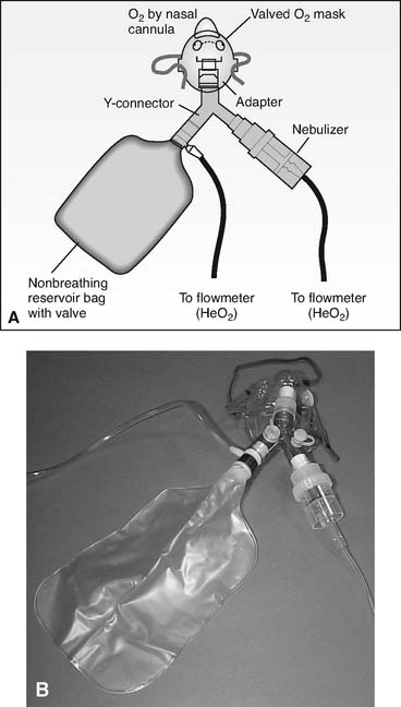
1. Nonrebreather mask
If the patient is being treated for asthma, the nonrebreather mask can be modified to accept a small-volume nebulizer for bronchodilator medication delivery. (See Figure 6-18.) Care must be taken if the nebulizer is powered by the heliox mix, as shown. Some nebulizers will not operate normally. It may be necessary to increase the heliox flow by 50% to 100% from the usual rate of oxygen flow to get the unit to operate properly. Others simply choose to power the nebulizer with oxygen, as intended, for the treatment.
| Helium/Oxygen Ratio | Heliox Factor | |
|---|---|---|
| 1. | 80% helium/20% oxygen | 1.8 |
| 2. | 70% helium/30% oxygen | 1.6 |
| 3. | 60% helium/40% oxygen | 1.4 |
Example: Observed oxygen flow of 10 L/min × 1.8 = 18 L/min actual heliox flow.
Example: Observed oxygen flow of 10 L/min × 1.6 = 16 L/min actual heliox flow.
Example: Observed oxygen flow of 10 L/min × 1.4 = 14 L/min actual heliox flow.
 .
. .
. .
.2. Mechanical ventilator
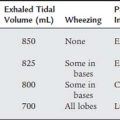
Delivering a helium/oxygen mix through a ventilator presents several technical challenges. First, select a ventilator that has been approved by the U.S. Food and Drug Administration (FDA) to deliver a heliox mix. In many ventilators, the decreased density of helium causes flow and volume sensors (usually a flow-type pneumotachometer) to read inaccurately. If a nonapproved ventilator needs to be used, it is recommended that pressure ventilation be used rather than volume ventilation. The risk with volume ventilation is the potential delivery of a larger tidal volume than that set on the ventilator. In addition, measure the patient’s exhaled tidal volume with a bellows-type spirometer rather than a pneumotachometer.
MODULE C
1. Manipulate oxygen hoods by order or protocol (ELE code: IIA12c) [Difficulty: ELE: R, Ap]
a. Get the necessary equipment for the procedure
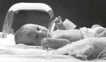
Oxygen hoods are used to provide a warmed aerosol, humidity, and a controlled oxygen percentage to pediatric patients who weigh no more than 18 lb (8.2 kg). (See Figure 6-19.) Often the oxygen hood and the infant are placed inside of an incubator for better control of the environment and maintenance of body temperature. (See Chapter 8 for discussion on incubators.)
b. Put the equipment together and make sure that it works properly
When an oxygen hood is used, the following procedures should be observed:
c. Troubleshoot any problems with the equipment
Make sure that the oxygen and aerosol delivery systems are working properly and that the oxygen percentage can be maintained. Be aware of the noise level inside the hood to minimize damage to the infant’s hearing. The sound level should be monitored and kept well below 65 dB.
2. Manipulate oxygen tents by order or protocol (ELE code: IIA12b) [Difficulty: ELE: R, Ap]
a. Get the necessary equipment for the procedure
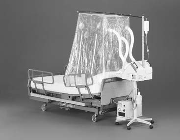
Oxygen tents formerly were used for adults but now are used only for children who are too large and active for an oxygen hood. The tent is a clear plastic canopy used to control the environment by providing a cooled aerosol, humidity, and a controlled oxygen percentage (Figure 6-20).
b. Put the equipment together and make sure that it works properly
In addition to setup of the tent, the following must be done to make it operational:
3. Manipulate air entrainment devices and masks by order or protocol (ELE code: IIA1b) [Difficulty: ELE: R, Ap, An]
a. Get the necessary equipment for the procedure
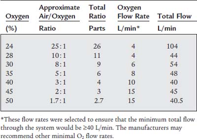
Air entrainment masks are called high-flow devices because they are designed to provide the patient with a controlled oxygen percentage at a high enough flow rate to ensure that all of the patient’s inspiratory flow needs are met (Figure 6-21). To ensure that this happens, the total flow through the mask must be equal to or greater than the patient’s peak inspiratory flow. (The interested learner is encouraged to read about the Bernoulli principle, which regulates the mixing of fluids as the result of a decrease in pressure caused by a jet.) These masks are sometimes called Venturi masks, Venti masks, jet-mixing, and high airflow with oxygen enrichment (HAFOE) systems. See Table 6-5 for specific information on available air entrainment masks.
b. Put the equipment together and make sure that it works properly
Depending on the manufacturer, the mask my come as a completed unit, may have air entrainment adapters to add to the mask, or may have an air entrainment adapter to adjust to set the desired oxygen percentage. See Table 6-5 for the recommended starting oxygen flow rate for the different oxygen percentage masks. Because it is difficult to ensure that the patient’s peak inspiratory flow is matched by the gas flow through the mask, the following guidelines are recommended:
Some patients may complain that the gas coming through the mask is dry. To resolve this problem, some manufacturers have designed an aerosol adapter to add at the jet. A separate bland aerosol then is added to the room air (21% oxygen that enters the jet stream). Make sure that the adapter fits properly and does not interfere with or block the jet or room air entrainment ports. Do not add a bubble-type humidifier to the jet on the mask because the high backpressure through the jet will cause the pressure relief (pop-off) valve to open, and the oxygen will leak out.
4. Manipulate a low-flow nasal cannula by order or protocol (ELE code: IIA1a) [Difficulty: ELE: R, Ap, An]
a. Get the necessary equipment for the procedure
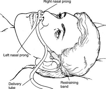
The traditional nasal cannula is a low-flow oxygen delivery tube that has been modified with two short prongs to deliver oxygen to the nostrils (Figure 6-22). Nasal cannulas come in neonatal, pediatric, and adult sizes based on the diameter of the prongs. Care must be taken to make sure that the patient’s nares are patent and are not plugged by a common cold, a deviated septum, or another unseen problem. This simple oxygen delivery device is used very widely because it is more comfortable for many patients than an air entrainment mask or other types of face masks. Current clinical practice guidelines indicate that, in an adult, an oxygen flow of 4 L/min or less does not require additional humidification if the patient has a normal upper airway.
b. Put the equipment together and make sure that it works properly
If an adult is getting from 1 to 4 L/min of oxygen and complains of nasal dryness, or if a higher flow is given, humidification will have to be provided. Often this is a bubble-type humidifier, as discussed in Chapter 8. Make sure that it is properly filled with sterile water and that the oxygen bubbles through it. Check the high-pressure pop-off valve for pressure release and a whistling sound. Before placing the cannula on the patient, check to see that the oxygen is flowing through the tubing. If available, use a cannula with curved prongs. They direct the gas flow toward the back of the nasal passages for better natural humidification and are better for patient comfort. Take care to avoid pulling the elastic restraining band too tightly around the head. Some brands loop the oxygen tubing over the ears to be drawn up snugly under the chin. Often this type is more comfortable than the types that have an elastic band.
The problem with a nasal cannula is that the delivered oxygen percentage is unreliable. Variations in the patient’s respiratory rate, I : E ratio, tidal volume, and minute volume result in different inhaled oxygen percentages. This is clearly unacceptable in an unstable patient in whom Pao2 values are being used to help judge the changing cardiopulmonary status. Because of this clinical limitation, this device and the other low-flow oxygen delivery systems in the discussions that follow should be used only with stable patients. In the adult, the delivered oxygen percentage can be estimated at approximately 4% for each liter of oxygen per minute (Table 6-6). Flows usually are limited to 6 L/min to avoid excessive irritation to the nasal passages. Flows usually are limited to no more than 1 to 2 L/min in infants and 4 L/min in older children. The pulse oximetry value or Pao2 level should be checked in patients of any age whenever a flow change is made or when the patient’s condition changes significantly.
TABLE 6-6 Estimated Delivered Oxygen Percentage in Adults Based on the Oxygen Liter Flow Through a Nasal Cannula
| Oxygen, L/min | Estimated Delivered Oxygen, % |
|---|---|
| 1 | 24 |
| 2 | 28 |
| 3 | 32 |
| 4 | 36 |
| 5 | 40 |
| 6 | 44 |
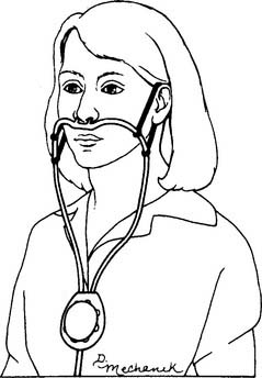
5. Manipulate an oxygen-conserving nasal cannula by order or protocol (ELE code: IIA9b) [Difficulty: ELE: R, Ap, An]
b. Put the equipment together and make sure that it works properly
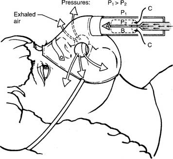
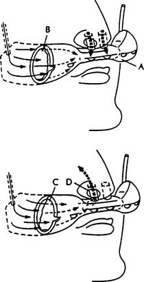
At least two different types of oxygen-conserving cannulas are found. Figure 6-23 shows a reservoir nasal cannula and how it operates. It has an 18-mL reservoir that fills when the patient exhales and gives up its oxygen bolus during the next inspiration. Figure 6-24 shows a pendant nasal cannula with its reservoir that hangs on the chest.
c. Troubleshoot any problems with the equipment
Both types of cannulas can have problems with tubing disconnections or kinks that can happen with any type of cannula. The only problem that is unique to both of these units is failure of the diaphragm, which moves back and forth as the reservoir fills and empties. This membrane may wear out after about a week and prevent the reservoir from filling or emptying properly. Watch as the patient breathes to make sure that the diaphragm is moving properly. If not, replace the cannula.
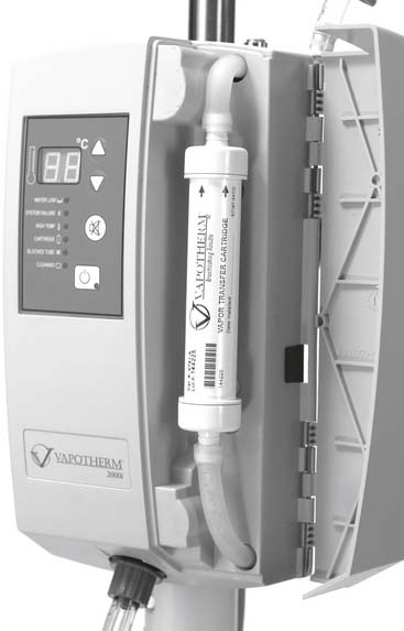
6. Manipulate a high-flow nasal cannula by order or protocol (ELE code: IIA1c) [Difficulty: ELE: R, Ap, An]
b. Put the equipment together and make sure that it works properly
Figure 6-25 shows a Vapotherm 2000i that is opened to show the vapor transfer cartridge. Water is continuously supplied into the unit and is warmed before entering the cartridge to be vaporized to humidify the patient’s oxygen. The temperature can be adjusted but usually is kept at body temperature. A pediatric cartridge will be used for a flow of 1 to 8 L/min. An adult cartridge will be used for flows of 5 to 40 L/min. An oxygen hose is attached at the bottom of the unit and then is attached to the patient’s nasal cannula. It is possible to attach the patient’s nasal catheter (rarely used clinically anymore) or transtracheal oxygen catheter. The flow of oxygen is adjusted to meet the patient’s clinical goal for oxygenation. The higher the oxygen flow, the higher the delivered oxygen percentage—possibly up to 100% oxygen.
7. Manipulate oxygen masks: simple oxygen mask, partial-rebreathing mask, nonrebreathing mask, and face tent, by order or protocol (ELE code: IIA1a) [Difficulty: ELE: R, Ap, An]
c. Troubleshoot any problems with the equipment
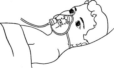
1. Simple oxygen mask
This mask, like all others, is designed to fit over the patient’s nose and mouth and act as an oxygen reservoir for the next breath (Figures 6-26 and 6-27). Various adult and pediatric sizes are available, and the patient should wear one that best fits the facial contours and size of the face. This is recommended for comfort, as well as to try to increase the inspired oxygen percentage by decreasing the amount of room air that is inspired. However, because a simple oxygen mask does not provide all of the patient’s tidal volume gas, it is classified as a low-flow device. Exhaled breath escapes through the exhalation ports. The patient’s breathing pattern affects the amount of room air that is breathed in through the same exhalation ports. These ports also are important in case the oxygen flow to the mask is cut off.
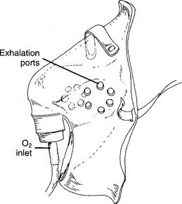
Figure 6-26 Close-up view of a simple oxygen mask.
(From McPherson SP: Respiratory care equipment, ed 4, St Louis, 1990, Mosby.)
2. Partial-rebreathing mask
The partial-rebreathing mask has a 500- to 1000-mL plastic bag added to the mask to act as an oxygen reservoir for the next breath (Figures 6-28, 6-29, and 6-30). Child- and adult-size masks are commonly available. When properly applied, the first third of the patient’s exhaled gas from the anatomic dead space is exhaled back into this bag. This gas is close to pure oxygen and has no carbon dioxide. Exhaled breath escapes through the exhalation ports. The patient’s breathing pattern affects the amount of room air that is breathed in through the same exhalation ports. Because of this room air entrainment, a partial-rebreathing mask is classified as a low-flow device. These ports also are important in case the oxygen flow to the mask is cut off; the patient will breathe in room air. The added reservoir of oxygen results in a higher percentage being given to the patient than with a simple oxygen mask. In all cases, set an oxygen flow high enough that the reservoir bag does not collapse by more than one-third on inspiration. For example, an initial oxygen flow of between 6 and 10 L/min should provide approximately 35% to 80% inspired oxygen.
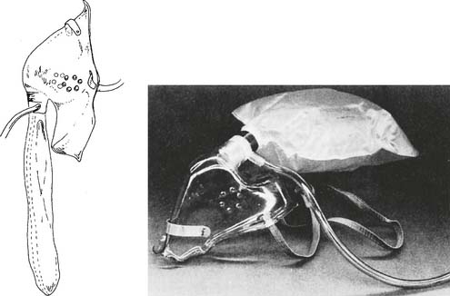
Figure 6-28 Outside view of a partial-rebreathing mask.
(From McPherson SP: Respiratory care equipment, ed 4, St Louis, 1990, Mosby.)
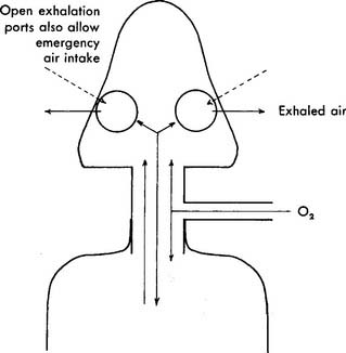
Figure 6-29 Cutaway view of a partial-rebreathing mask showing gas flow.
(From Thalken FR: Medical gas therapy. In: Scanlan CL, Spearman CB, Sheldon RL, editors: Egan’s fundamentals of respiratory care, ed 5, St Louis, 1990, Mosby.)
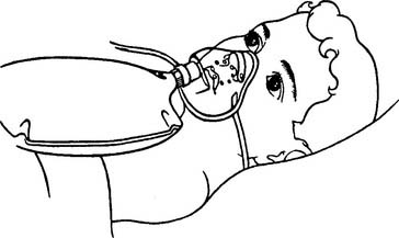
Figure 6-30 Child wearing a partial-rebreathing mask.
(From Gaebler G, Blodgett D: Gas administration. In Blodgett D, editor: Manual of pediatric respiratory care procedures, Philadelphia, 1982, Lippincott.)
A bubble humidifier often is added so that the gas is not dry. Make sure that it works properly, that the oxygen is flowing through the tubing, and that the reservoir bag has been filled before putting it on the patient. Adjust the flow as needed to ensure that the reservoir does not collapse by more than one-third on inspiration. This ensures that the mask and the reservoir are filled with as much oxygen as possible. A pulse oximetry value or Pao2 level should be checked whenever a flow change is made, or when the patient’s condition changes significantly.
3. Nonrebreathing mask
The nonrebreathing mask initially looks like the partial-rebreathing mask with its plastic bag added as an oxygen reservoir for the next breath (Figures 6-31 and 6-32). However, it should be noted that a one-way valve has been added between the mask and the reservoir bag. This allows the bag to be filled with pure oxygen that is available for the next breath. No exhaled gas can enter the reservoir. Two (sometimes one) one-way valves are added to the exhalation ports on the mask. In theory, with a tight-fitting mask and a high enough oxygen flow, the patient breathes in only oxygen from the mask and reservoir and no room air. However, because of leaks between the mask and the patient’s face, the nonrebreathing mask is classified as a low-flow device. Exhaled breath escapes through the exhalation ports as with the partial-rebreathing mask. Not shown is an emergency pop-in valve that allows room air to be drawn into the mask if the oxygen supply is cut off. Adult and pediatric sizes are available. The mask should be conformed to fit the patient’s facial contours and size as much as possible. As mentioned earlier, this is for comfort and to try to increase the inspired oxygen percentage by decreasing the amount of room air that is inspired. In theory, it is possible to deliver 100% oxygen with this mask if the oxygen flow is high enough and the mask is airtight over the face. However, experience has shown that the disposable masks that are usually available in the hospital do not prevent room air from being drawn in. In all cases, set an oxygen flow high enough that the reservoir bag does not collapse by more than one-third on inspiration. For example, an initial oxygen flow between 8 and 10 L/min should provide approximately 60% to 80% (or more) inspired oxygen.
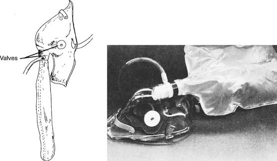
Figure 6-31 Outside view of a nonrebreathing mask.
(From McPherson SP: Respiratory care equipment, ed 4, St Louis, 1990, Mosby.)
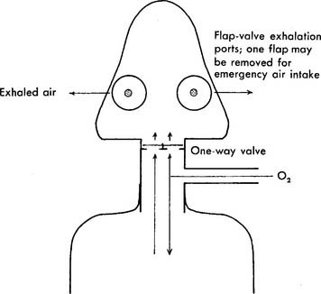
Figure 6-32 Cutaway view of a nonrebreathing mask showing gas flow.
(From Thalken FR: Medical gas therapy. In: Scanlan CL, Spearman CB, Sheldon RL, editors: Egan’s fundamentals of respiratory care, ed 5, St Louis, 1990, Mosby.)
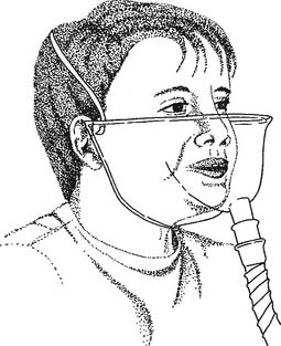
4. Face tent
These masks are designed to fit around the patient’s neck, under the jaw, and around the cheeks in front of the ears. The front edge should be higher than the level of the patient’s nostrils (Figure 6-33). Face tents sometimes are used to provide oxygen to a patient who cannot wear a mask or cannula because of oral and nasal trauma, burns, or surgery. The patient using a face tent should be sitting as upright as possible, because oxygen is heavier than air and tends to settle in the mask around the patient’s nose and mouth if the fit is tight. If the patient is lying flat or if the mask fits loosely, the oxygen will simply “pour” down out of it. This makes it difficult to know with any certainty what inspired oxygen percentage is available to the patient. Flows of 5 to 10 L of oxygen per minute are commonly used with adults.
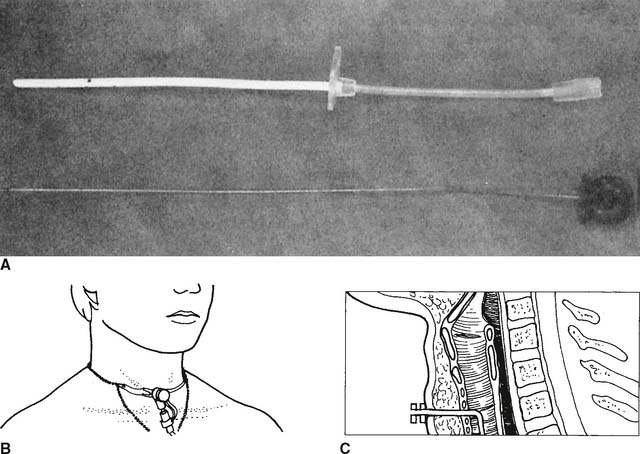
8. Manipulate a transtracheal oxygen catheter by order or protocol (ELE code: IIA1a) [Difficulty: ELE: R, Ap, An]
a. Get the necessary equipment for the procedure
The transtracheal oxygen (TTO2) catheter is a 20-cm-long flexible, hollow plastic tube (Figure 6-34). This low-flow oxygen delivery device is inserted into the trachea via a puncture procedure at the suprasternal notch. To date, only adults with COPD have had the procedure performed. Oxygen is delivered directly into the trachea. The patient’s oxygenation can be maintained at lower oxygen flows than are needed by a regular face mask or nasal cannula.
b. Put the equipment together and make sure that it works properly
9. Manipulate tracheostomy appliances: mask/collar and Brigg’s adapter/T-piece, by order or protocol (ELE code: IIA1a) [Difficulty: ELE: R, Ap, An]
c. Troubleshoot any problems with the equipment
1. Tracheostomy mask/collar
The adult or pediatric tracheostomy mask or collar is shaped to fit over a tracheostomy tube or stoma to provide oxygen and aerosol (Figure 6-35). Because the patient’s upper airway is bypassed, a nebulizer is used for humidity. It is usually an air entrainment type of device, so the oxygen percentage can be adjusted. Make sure that the nebulizer is filled with sterile water; if there is a high-pressure pop-off valve, make sure that it is working and that adequate mist is flowing through to the mask before putting it on the patient.
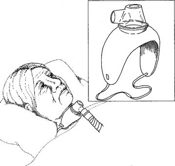
Because the tracheostomy mask is an open system without reservoir, it is difficult to guarantee the patient’s inspired oxygen percentage. Set the gas flow high enough to make a “cloud” of aerosol around the tracheostomy. If an excess of aerosol can be seen around the tracheostomy during inspiration, it is likely that the desired oxygen percentage is being delivered. Analyze the oxygen percentage from inside the mask to try for as much accuracy as possible. A pulse oximetry value or Pao2 level should be checked whenever a flow change or oxygen percentage change is made, or when the patient’s condition changes significantly.
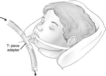
2. Brigg’s adapter/T-piece
The Brigg’s adapter or T-piece is designed to provide air or supplemental oxygen and aerosol to an endotracheal or tracheostomy tube. It has one 15-mm inner diameter (ID) opening that fits over any endotracheal or tracheostomy tube adapter. The other two openings are 22 mm outer diameter (OD) so that aerosol tubing can be added (Figure 6-36). A nebulizer is commonly used for humidity because the patient’s upper airway is bypassed. Make sure that the nebulizer is filled with sterile water; if there is a high-pressure pop-off valve, make sure it is working and that adequate mist is flowing through to the adapter before putting it on the patient. The nebulizer is usually an air entrainment type of device, so the oxygen percentage can be adjusted.
MODULE D
2. Adjust the flow or gas concentration (Code: IIIF2e2) [Difficulty: R, Ap; WRE: An]
The indications for all of the specialty gases are listed in Box 6-1. Although none of these gases is used widely in respiratory care, all can be very beneficial when indicated.
a. He/O2 (heliox) therapy
Patients who benefit from He/O2 therapy can have an upper airway obstruction problem (tumor) or a lower airway obstruction problem (asthma). Because helium atoms are so much smaller than nitrogen molecules, patients find that their work of breathing is greatly reduced. Normoxic patients usually are given a mix of 80% helium and 20% oxygen, whereas hypoxic patients are given 70% helium and 30% oxygen or 60% helium and 40% oxygen. If more oxygen is needed, small-bore oxygen tubing can be used to add it into the mask or reservoir bag, or a special closed system will have to be assembled from components.
b. Nitric oxide therapy
Usually one question deals with treating a patient with pulmonary hypertension. Inhaled nitric oxide in the range of 5 to 15 parts per million (ppm) is indicated. The question often includes information that shows the patient has an increased pulmonary vascular resistance (PVR), indicating pulmonary hypertension. See Chapter 5 and Box 5-2 for more information on PVR.
c. O2/CO2 (carbogen) therapy
Carbon dioxide is available in tanks of pure CO2 or a mix of 5%:95% or 10%:90% (carbon dioxide : oxygen ratio). Carbogen is used during cardiopulmonary bypass procedures to maintain the patient’s PaCO2. Common clinical uses are listed in Box 6-1. Because inhaling carbon dioxide runs counter to a person’s normal exhalation of CO2, the patient’s PaCO2 can increase with resulting respiratory acidosis. So, the patient’s arterial blood gas values, vital signs, and mental status must be monitored closely. Be prepared to decrease the carbogen percentage or stop the breathing of carbogen if the patient shows any adverse signs or symptoms.
The treatment of hiccups usually requires only that the patient rebreathe from a paper bag. If necessary, a small amount of carbon dioxide can be added to stop the hiccups.
MODULE E
1. Analyze available information to determine the patient’s pathophysiologic state (Code: IIIH1) [Difficulty: ELE: R, Ap; WRE: An]
The goal of oxygen therapy is to correct the patient’s hypoxemia. Obtain an ABG sample or perform pulse oximetry, as needed, to determine the patient’s oxygenation. Review the complete discussion of these subjects in Chapter 3. The specialty gases (heliox, nitric oxide, and carbogen) are needed to help manage specific clinical problems.
2. Determine the appropriateness of the prescribed therapy and goals for the identified pathophysiologic state (Code: IIIH3) [Difficulty: ELE: R, Ap; WRE: An]
a. Terminate the treatment or procedure based on the patient’s response (Code: IIIF1) [Difficulty: ELE: R, Ap; WRE: An]
b. Recommend discontinuing the treatment or procedure based on the patient’s response (Code: IIIG1i) [Difficulty: ELE: R, Ap; WRE: An]
As was discussed at the beginning of the chapter, several possible hazards occur with the use of oxygen therapy. The NBRC is most likely to ask questions related to the use of or increase or decrease in oxygen in a patient with COPD. The specialty gases can be discontinued when the clinical problem (see Box 6-1) has been corrected.
MODULE F
1. Develop the outcomes of respiratory care protocols (Code: IIIH6b) [Difficulty: ELE: R, Ap; WRE: An]
3. Monitor the outcomes of respiratory care protocols (Code: IIIH7b) [Difficulty: ELE: R, Ap; WRE: An]
c. Independently change the mode of administering the oxygen (ELE code: IIIF2d1) [Difficulty: R, Ap, An]
Every patient’s oxygen percentage or flow must be tailored to meet the patient’s clinical goals. Usually this means keeping patients who are acutely hypoxemic at a Pao2 level between 60 and 100 torr and an Spo2 value between 90% and 97%. Exceptions, when the blood oxygen level is kept as high as possible, include cardiopulmonary resuscitation and treatment for carbon monoxide poisoning. Another exception is the patient with COPD who is hypoxemic and hypercarbic. Usually these patients’ conditions are maintained with a moderate hypoxemia. The Pao2 level should be between 50 and 60 torr and the Spo2 value between 85% and 90%. It is imperative to keep the oxygen in this relatively narrow range. Further hypoxemia will result in pulmonary hypertension and cor pulmonale. Cardiac dysrhythmias or arrest and death can occur if the hypoxemia is severe (<40 torr). Oxygen levels in the normal range (>60 torr) may result in blunting of the hypoxic drive. This can result in bradypnea and even greater carbon dioxide retention with corresponding acidemia. When the carbon dioxide pressure (PaCO2) level exceeds 80 to 90 torr, many patients become drowsy or somnolent. The goal of treatment is to decrease the Fio2 to reduce the Pao2 level to 50 to 60 torr. This, in turn, stimulates the hypoxic drive so that the patient increases his or her ventilation. See Chapter 3 for a complete discussion of the interpretation of arterial blood gas values.
AARC Clinical Practice Guideline. Oxygen therapy in the acute care hospital. Respir Care. 1991;36:1410-1413.
AARC Clinical Practice Guideline. Oxygen therapy in the home or extended care facility—2007 revision & update. Respir Care. 2007;52:1063-1068.
American Association for Respiratory Care. Clinical practice guideline: oxygen therapy for adults in the acute care facility: 2002 revision and update. Respir Care. 2002;47:717.
American Association for Respiratory Care. Clinical practice guideline: selection of an oxygen delivery device for neonatal and pediatric patients: 2002 revision and update. Respir Care. 2002;47:707.
Bageant RA. Oxygen analyzers. Respir Care. 1976;21:410-416.
Boggs W. High-flow nasal cannula inadequate substitute for CPAP in infants, Respiratory Therapy Magazine. (online): www.rtmagazine.com/reuters_article.asp?id=20080114clin007.html.
Burton GG, Hodgkin JE, Ward JJ, editors. Respiratory care, a guide to clinical practice, ed 4, Philadelphia: Lippincott-Raven, 1997.
Cairo JM. Manufacture, storage, and transport of medical gases. In Cairo JM, Pilbeam SP, editors: Mosby’s respiratory care equipment, ed 8, St Louis: Mosby, 2010.
Cairo JM, Pilbeam SP. Mosby’s respiratory care equipment, ed 8. St Louis: Mosby, 2010.
Dantzker DR, MacIntyre NR, Bakow ED, editors. Comprehensive respiratory care. Philadelphia: WB Saunders, 1995.
Datex-Ohmeda. INOvent delivery system. http://www.datex-ohmeda.com, January 1, 2001.Eubanks DH, Bone RC. Comprehensive respiratory care, ed 2. St Louis: Mosby, 1990.
Fink JB, Hunt GE, editors. Clinical practice in respiratory care. Philadelphia: Lippincott-Raven, 1999.
Gaebler G, Blodgett D. Gas administration. In: Blodgett D, editor. Manual of pediatric respiratory care procedures. Philadelphia: Lippincott, 1982.
Gluck EH, Onorato DJ, Castriotta R. Helium-oxygen mixtures in intubated patients with status asthmaticus and respiratory acidosis. Chest. 1990;98:693-698.
Hess DR. Nonconventional respiratory therapeutics. In: Hess DR, MacIntyre NR, Mishoe SC, et al, editors. Respiratory care principles & practices. Philadelphia: WB Saunders, 2002.
Hill KV. Oxygen therapy. In Aloan CA, Hill TV, editors: Respiratory care of the newborn and child, ed 2, Philadelphia: Lippincott-Raven, 1997.
Hollman GA, Shen G, Zeng L, et al. Helium-oxygen improves clinical asthma scores in children with acute bronchiolitis. Crit Care Med. 1998;26:1731-1736.
Hunt GE. Gas therapy. In: Fink JB, Hunt GE, editors. Clinical practice in respiratory care. Philadelphia: LippincottRaven, 1999.
INOTherapeutics. Homepage. http://www.inotherapeutics.com, January 1, 2001.
Kass JE, Castriotta RJ. Heliox therapy in acute severe asthma. Chest. 1995;107:757-760.
Kemper KJ, Ritz RH, Benson MS, Bishop MS. Helium-oxygen mixture in the treatment of postextubation stridor in pediatric trauma patients. Crit Care Med. 1991;19:356-359.
Kudukis TM, Manthous CA, Schmidt GA, et al. Inhaled helium-oxygen revisited: Effect of inhaled helium-oxygen during the treatment of status asthmaticus in children. J Pediatr. 1997;131:333-334.
McCoy R. Oxygen-conserving techniques and devices. Respir Care. 2000;45:95-103.
McPherson SP. Respiratory care equipment, ed 5. St Louis: Mosby, 1995.
Saposnick AB. Medical gases—manufacture, storage, and delivery. In: Hess DR, MacIntyre NR, Mishoe SC, et al, editors. Respiratory care principles & practices. Philadelphia: WB Saunders, 2002.
Saposnick AB, Hess DR. Oxygen therapy: Administration and management. In: Hess DR, MacIntyre NR, Mishoe SC, et al, editors. Respiratory care principles & practices. Philadelphia: WB Saunders, 2002.
Schaeffer EM, Pohlman A, Morgan S, Hall JB. Oxygenation in status asthmaticus improves during ventilation with helium-oxygen. Crit Care Med. 1999;27:2666-2670.
Shapiro BA, Harrison RA, Cane RD, et al. Clinical application of blood gases, ed 4. St Louis: Mosby, 1989.
Shapiro BA, Kacmarek RM, Cane RD, et al, editors. Clinical application of respiratory care, ed 4, St Louis: Mosby, 1991.
Tassaux D, Jolliet P, Thouret JM, et al. Calibration of seven ICU ventilators for mechanical ventilation with helium-oxygen mixtures. Am J Respir Crit Care Med. 1999;160:22-32.
Ward JJ. Equipment for mixed gas and oxygen therapy. In Branson RD, Hess DR, Chatburn RL, editors: Respiratory care equipment, ed 2, Philadelphia: Lippincott Williams & Wilkins, 1999.
Ward JJ. Medical gas therapy. In Burton GC, Hodgkin JE, Ward JJ, editors: Respiratory care: a guide to clinical practice, ed 4, Philadelphia: Lippincott-Raven, 1997.
Waugh JB, Granger WM. An evaluation of 2 new devices for nasal high-flow gas therapy. Respir Care. 2004;49:902-906.
Whitaker K. Comprehensive perinatal and pediatric respiratory care, ed 2. Albany, NY: Delmar, 1997.
White GC. Equipment theory for respiratory care, ed 4. Albany, NY: Delmar, 2005.
Wilkins RL, Stoller JK, Kacmarek RM, editors. Egan’s fundamentals of respiratory care, ed 9, St Louis: Mosby, 2009.
Wojciechowski WV. Respiratory care sciences: An integrated approach, ed 3. Albany, NY: Delmar, 2000.
Youtsey JW. Oxygen and mixed gas therapy. In Barnes TA, editor: Core textbook of respiratory care practice, ed 2, St Louis: Mosby, 1994.
SELF-STUDY QUESTIONS FOR THE ENTRY LEVEL EXAM See page 587 for answers
SELF-STUDY QUESTIONS FOR THE WRITTEN REGISTRY EXAM See page 612 for answers