Ocular ultrasound in the intensive care unit
(CONSULTANT LEVEL EXAMINATION)
Overview
Multipurpose ultrasound systems offer a variety of eye and orbit imaging techniques relevant to critical care. Bedside ocular ultrasound can be used for the following purposes: (1) timely identification of threats to ocular health and vision and prevention of vision-related disability in trauma,1–4 (2) assessment of nontraumatic acute change in vision and the need for immediate ophthalmologic consultation,1 (3) measurement of the diameter of the optic nerve sheath (ONSD) as a surrogate measure for intracranial pressure (ICP),5–9 (4) assessing the integrity of the bony orbit and periorbital tissues in severe craniofacial trauma,10 and (5) assessing the pupillary reactivity when visual access to the pupil is impeded.11 However, ocular ultrasound applications are somewhat unique and not standardized at this time, whereas only ONSD measurements have been partially studied in the intensive care unit (ICU) environment. This chapter illustrates specific guidance for ultrasound equipment choice and adjustment, general ocular scanning techniques, and tips to maximize the utility of the ultrasound method for eye and orbit imaging.
Equipment and settings
Equipment controls most frequently used in eye/orbit imaging are gain, TGC (time gain compensation), focus, and power output (see Chapter 1). Additional optimization techniques can be invoked as dictated by specific circumstances.
We highly recommend creating a customized eye/orbit preset that could be selected within seconds from the preset menu of the machine. This will save valuable time; ensure standardization; and serve as a safety, training, and quality assurance mechanism. An example is (1) select the factory-made thyroid preset from the preset menu; (2) adjust depth to 4 cm; (3) move the focus marker to 2.5 cm; (4) adjust MI to 0.2312,13 with the power output control; (5) set TGC rheostats at their midrange; (6) scan a patient with indications for ocular ultrasound (e.g., to measure ONSD), and after identifying the terminal optic nerve, adjust gain appropriately; (7) save current settings under a new custom preset name (e.g., “eye-orbit”); (8) scan several patients to “fine-tune” the preset, and resave it with improved settings every time; (9) when satisfied, copy the preset to all machines in the department (if same model), or reproduce its features manually if machines are different. Make sure that additional setting changes do not increase MI; if they do, reduce power output accordingly. Note that perfect presets do not exist, and machine adjustments (at least, gain and TGC) will still be necessary in most patients.
General scanning technique and primary views
Eye and orbit scanning in the ICU is done with closed eyelids. The scope of the examination will depend on patient’s history, status, and open clinical questions. An ICU patient may need only a limited posterior pole and optic nerve examination. However, in trauma patients, the scope of the examination may be broader (see Chapters 1, 51, and 57), and thus a holistic approach (HOLA) ultrasound ocular protocol would include scanning of the eyelids, globe and orbital contents, as well as investigation of the frontal, temporal, zygomatic and nasal bones and overlying tissues. The eye examination proper, in its turn, may be directed at checking the overall integrity of the globe or at a more thorough scrutiny of its entire volume.
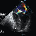
The AP views (sagittal and axial) are used for ocular anatomy survey and allow viewing practically all ocular structures to rule out macroscopic pathology (Figure 6-1A-C). The oblique sagittal view of the optic disk and terminal optic nerve is used to assess the shape of the optic disk, the terminal optic nerve with its meninges, and as a backup approach to measure ONSD in a sagittal plane (Figure 6-1E). This view may offer a possibility to visualize a longer span of the optic nerve by using a small rotation of the imaging plane. Note that the transducer is placed laterally to the cornea so that the imaging plane bypasses the anterior structures (cornea, anterior chamber, ciliary body, and the lens). The axial view from lateral approach allows avoiding the edge-shadowing artifact that in AP views obscures the peripheral zones of the vitreous humor and the globe wall near the equator (Figure 6-1D). The oblique axial view with optic disk and optic nerve head is the quickest and the most reproducible way to measure ONSD (Figure 6-2). The transducer position is on the upper eyelid (preferably with a downward gaze) with the marker to the right (for both eyes), and the plane bypasses the anterior structures. The resulting target image is similar to the sagittal view (see Figure 6-1E). The coronal view of the iris is used to assess the circular symmetry of the iris and the pupillary reactivity to light (Figure 6-3).
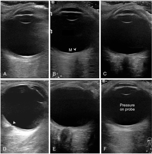
Figure 6-1 Standardized primary views in eye ultrasound. A, Anteroposterior (AP) view bisecting the globe sagittally from the corneal vertex to the macula (nerve not in view). Note eyelashes with trapped air affecting most of the inferior (right) part of the image. B, AP axial view with the disk area (arrowhead) and macular area (M). C, Similar to A; however, the imaging plane is shifted medially to pass through the optic nerve head. Although the nerve is visible, this image cannot be used for optic nerve sheath diameter (ONSD) measurement. D, Axial view, lateral approach with a good depiction of the equatorial areas. Note the cup of the optic disk (arrowhead). E, Oblique axial view through the upper lid, bypassing the anterior segment. This is an excellent image for ONSD measurement. F, Same plane as in A, with undue pressure on the probe. Note the flattened cornea.
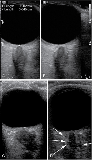
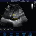
Figure 6-2 Optic nerve sheath diameter (ONSD) measurement technique and examples. A, Determination of the measurement location (3 mm from the vitreoretinal interface). B, Caliper placement for ONSD measurement. C, A posteriorly flattened globe; tortuous and edematous optic nerve and a severely dilated, hypoechoic, and kinked sheath with ONSD greater than 10 mm. D, An image of the optic nerve with a prominent (>7.5 mm) optic nerve sheath. Note the multiple anechoic fluid-filled spaces that have become visible as their size exceeded the resolution limit of the given probe at the given depth.
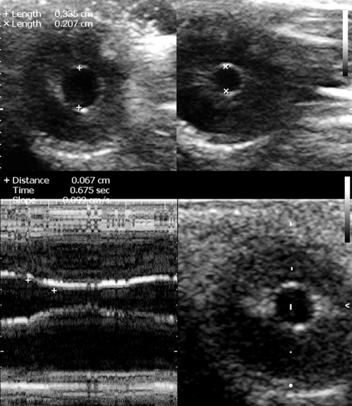
Figure 6-3 The coronal view of the globe in the plane of the iris at baseline (top left) and upon consensual response to contralateral stimulation with light (top right). Below, M-mode cursor is placed over the middle of the iris to record the reflex against time and measure the degree of constriction, the time of response, and its velocity (slope).
Trauma
The risks of eye injury are the highest in military combat14 but always present in both professional and daily human activity. Ultrasound evaluation of the eye is indicated in any case of trauma with the following findings: disturbance of vision of any extent, suspected breech of globe integrity with or without a foreign body, any abnormal finding during visual inspection of the globe, pain or any other persisting symptom, and edema or bruising of periorbital tissues and eyelids. Use of ultrasound with traumatic eye injuries is highly sensitive and specific when performed by an experienced operator using the appropriate transducer and technique.4,15 We will not describe the specific imaging signs of traumatic eye injuries are not described in this chapter because they are widely available from other sources.16
Optic nerve sheath diameter measurements and new quality criteria
The intraorbital cerebrospinal fluid (CSF) space (i.e., the space between the dural sheath of the optic nerve and the pia-covered nerve proper) is contiguous with the intracranial CSF space.17 The authors of this chapter, as well as many others, have demonstrated a strong positive correlation between the ONSD and the ICP in animal and cadaveric models as well as in clinical observational trials, the latter primarily in head trauma or cerebrovascular accidents.5–9,18,19 A leading notion of the published works was to demonstrate the correlation but also to find a “cutoff value” of ONSD that would indicate a pathologic level of ICP with high confidence. The suggested “cutoff,” or “threshold,” values have varied between trials in the range of 5.0 to 5.9 mm. In a meta-analysis of six trials involving 231 patients, Dubourg et al 20 found ONSD to have “a good level of diagnostic accuracy for detecting intracranial hypertension” and suggested that ONSD technique can help make triage or invasive monitoring decisions. Notwithstanding the exhaustive statistical analysis of the data, and the resulting good agreement among the six highest-quality trials, their results remain applicable only to the patient groups involved and do not necessarily discern weaknesses associated with the imaging and measurement technique and the accuracy of recognition of the optic nerve sheath borders (see quality criteria below). A general weakness, besides the lack of standardization and quality control of ONSD measurements, is the lack of normal population data that would provide an alternative approach to ONSD data interpretation, because age, gender, race, anthropometric factors, medical history, and even professional background most likely influence the individual’s baseline (premorbid) ONSD. For these reasons, we strongly recommend exercising caution in using hitherto published threshold values in clinical decisions on the one hand, and making serious efforts in attaining ultrasound views with clearly visible borders of the arachnoid space, on the other. The equipment requirements and the ultrasound views and technique for ONSD measurement are described in previous sections. The first and default view for this purpose is the near-axial (oblique axial) view through the upper eyelid, with a straight-to-downward gaze (see Figure 6-2). In case of gaze deviation in superior (frontal) direction, the lower eyelid should be used. The lateral axial view should be reserved as a backup view if the previous two views fail. As a minimum, one high-quality view of the posterior pole with the terminal optic nerve must be obtained from each side.
The quality criteria for ONSD measurements have not been well described in the literature. Images of quality acceptable for ONSD measurement are provided in Figure 6-2. Our suggested quality criteria are summarized below:
• ONSD measurement should not be made through the lens (even the edge of the lens may not be visible on the image); an example of unacceptable image for ONSD purposes is shown in Figure 6-1C.
• Sonographic differentiation (contrast) between the nerve proper and the arachnoid (CSF space) must be obvious (see Figures 6-1E and 6-2); measuring a “dark stripe” behind the globe without nerve and arachnoid differentiation is not acceptable.
• The outer border of the arachnoid must be identifiable for actual ONSD measurement; clear, well-focused images must thus allow confident measurement of the inner diameter of the dural sheath.
• Ideal views of the optic nerve demonstrate the point of its penetration into the globe, that is, “dark meets dark” (nerve meets vitreous without interposition of thick echogenic layer of the posterior sclera).
• Good views offer opportunities for additional information potentially useful with growing experience, such as tortuosity of the nerve, hypoechogenicity of the arachnoid, and its irregularity because of distention of CSF-containing “cells” (see Figure 6-2D); this also allows viewing the optic disk area protrusion into the globe and flattening of the posterior globe in chronic ICP elevations (premorbid), which may mimic acute states in ICU (see Figure 6-2C).
• Correct standardized measurements. Because the most distensible portion of the sheath is at the 3- to 4-mm distance from the vitreoretinal interface (see Figure 6-2A), measurements are performed at this level in a direction perpendicular to the axis of the nerve (see Figure 6-2B). In extreme gaze deviations, this may be difficult to achieve because of the acute angle between the nerve axis and the posterior wall of the globe. This may require repeated attempts or adjustment of gaze if possible.
• It is highly recommended to measure ONSD bilaterally and in more than one image frame. This is an important quality assurance mechanism.
• For ONSD trend monitoring, the previous record with images must be reviewed to ensure similar views and measurement technique. Prior images should be available at bedside (from the machine or in printout) for reference. ONSD measured in sagittal planes should not be compared with ONSD from axial planes.
ONSD values, if measured correctly, accurately reflect the anatomic dimension of the sheath at a specific point behind the globe. A high quality of measurements and consistent technique may facilitate monitoring the ICP trend in some patients, although previous evidence has been disappointing in this sense.7 This could be attributed to the fact that ONSD reaches a plateau at some point, and further distention may be too small to measure or be due to technical issues because ONSD measurements in early clinical studies have not been performed using refined methodology and according to strict image quality criteria. ONSD still holds promise for trend identification with increased measurement accuracy, at least in situations with rapidly rising ICP, when the difference in ICP between the two measurements is significant. One-time ONSD measurement should be considered with caution, and “cutoff” values reported in literature should be used as “alert levels” to prompt additional attention to ICP. The clinician must also remember that any ICU patient may have had a large ONSD before the current illness. As population distribution data become available and the quality standards are improved, better clinical criteria will likely emerge for both negative and positive prediction, and trend monitoring criteria may also be revised.
Pupillary light reflex assessment
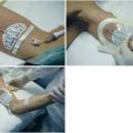
The method was initially developed for the U.S. Space Program and is not standardized for clinical use; only two successful case studies in trauma ICU patients have been published.11,21 The method has no real alternatives when visual access to the pupil is impossible, and its results are self-explanatory. Consensual pupillary light reflex is elicited with contralateral transillumination through the eyelids with both eyes closed. The pupillary light reflex ultrasound test can be conducted with a linear-array probe at the highest available frequency (e.g., 12-15 MHz), using the coronal primary view described earlier (see Figure 6-3 and Video 6-1). The method can be combined with ONSD measurements to evaluate a potentially catastrophic intracranial process. The method is difficult in unstable gaze. In cases of severe facial trauma, extreme care should be taken to avoid additional damage to the globe and other tissues.
Safety aspects
Diagnostic ultrasound has an excellent safety record. However, exposure of tissues to intense levels of ultrasound, well above those levels found with diagnostic ultrasound devices, has been shown to have damaging effects (see Chapter 1). Furthermore, delicate structures of the orbit, especially in trauma, can be damaged by mechanical force in case of unstable positioning, incautious movements of personnel, or involuntary movements of the subject. Use of irritant antiseptics for probe disinfection or inappropriate contact gels or lubricants can lead to chemical conjunctivitis. Failure to disinfect the transducer can potentially introduce pathogenic flora to the conjunctival sac. Therefore a set of safety rules is outlined below.
Mechanical safety expects that (1) operator must assume a stable and comfortable position before commencing the procedure; (2) adequate time for scanning must be available to avoid haste; (3) nonessential personnel must stay at distance; (4) good transducer manipulation technique must be used, including hand anchoring, use of bony prominences of the subject’s periorbital area, and use of both hands as necessary to reliably control transducer position and prevent transducer pressure at all times; and (5) no transducer pressure may be used as a means to improve the image quality. All mechanical safety measures are emphasized in trauma, especially if there is a slightest possibility of globe rupture.
Pearls and highlights
• Generic survey of regional ocular anatomy, focused imaging of the globe, measurement of the ONSD, and ultrasound assessment of pupil reactivity are all new eye and orbit ultrasound imaging techniques relevant to critical care.
• The HOLA ultrasound concept embraces both the anatomic context and the specific focused techniques in the ocular area. For example, a HOLA ultrasound ocular protocol in trauma patients would include scanning of the eyelids, globe, and orbital contents—including ONSD measurements—as well as investigation of the frontal, temporal, zygomatic and nasal bones, and overlying tissues.
• Eye imaging requires special safety measures to be implemented and followed.
• Standard multipurpose ultrasound machines with higher-frequency (10-14 MHz) transducers must be used unless severe facial edema requires deeper penetration.
• Strict image quality criteria (i.e., the recognition of both inner and outer borders of the arachnoid layer) should be applied to ensure the accuracy and validity of ONSD measurements.
• The “cutoff” values of ONSD measurements reflecting pathologic ICP have been reported at 5.7 to 5.9 mm. However, population distribution data for ONSD are not currently available, and most published data are from traumatic brain injury and cerebrovascular accident patients.
• Ultrasonic determination of pupillary reactivity may be a promising new technique in neurocritical monitoring. It is not standardized but can be used when indicated because its results are self-explanatory. This is an example of ultrasound being a part of the physical examination.
References
1. Blaivas, M, Theodoro, D, Sierzenski, PR. A study of bedside ocular ultrasonography in the emergency department. Acad Emerg Med. 2002; 9:791–799.
2. Sargsyan, AE, Dulchavsky, AG, Adams, J, et al. Ultrasound detection of simulated intra-ocular foreign bodies by minimally trained personnel. Aviat Space Environ Med. 2008; 79:58–61.
3. Chiao, L, Sharipov, S, Sargsyan, AE, et al. Ocular examination for trauma; clinical ultrasound aboard the International Space Station. J Trauma. 2005; 58:885–889.
4. Blaivas, M. Bedside emergency department ultrasonography in the evaluation of ocular pathology. Acad Emerg Med. 2000; 7:947–950.
5. Tsung, JW, Blaivas, M, Cooper, A, et al, A rapid noninvasive method of detecting elevated intracranial pressure using bedside ocular ultrasound: application to 3 cases of head trauma in the pediatric emergency department. Pediatr Emerg Car. 2005; 21:94–98.
6. Blaivas, M, Theodoro, D, Sierzenski, PR. Elevated intracranial pressure detected by bedside emergency ultrasonography of the optic nerve sheath. Acad Emerg Med. 2003; 10:376–381.
7. Karakitsos, D, Soldatos, T, Gouliamos, A, et al. Transorbital sonographic monitoring of optic nerve diameter in patients with severe brain injury. Transplant Proc. 2006; 38:3700–3706.
8. Soldatos, T, Karakitsos, D, Chatzimichail, K, et al. Optic nerve sonography in the diagnostic evaluation of adult brain injury. Crit Care. 2008; 12:R67.
9. Hansen, HC, Helmke, K. The subarachnoid space surrounding the optic nerves. An ultrasound study of the optic nerve sheath. Surg Radiol Anat. 1996; 18:323–328.
10. Kishibe, K, Saitou, S, Harabuchi, Y. [Significance of ultrasonography for nasal fracture]. Nihon Jibiinkoka Gakkai Kaiho. 2005; 108:8–14.
11. Sargsyan, AE, Hamilton, DR, Melton, SL, et al. Ultrasonic evaluation of pupillary light reflex. Crit Ultrasound J. 2009; 1:53–57.
12. , U.S. Department of Health and Human Services, U.S. Food and Drug Administration: Guidance for industry and FDA staff. Information for manufacturers seeking marketing clearance of diagnostic ultrasound systems and transducers, Document 560. U.S. Food and Drug Administration, Rockville, MD, 2008.
13. , Safety Group of the British Medical Ultrasound Society: Guidelines for the safe use of diagnostic ultrasound equipment. Ultrasoun. 2010; 18:52–59.
14. Nutaitis, MJ, Ocular trauma: history and examinationAllen B, Thach, eds.. Ophthalmic care of the combat casualty. Office of the Surgeon General at TMM Publications: Washington, DC, 2003; 59–78.
15. Blaivas, M, Theodoro, D, Sierzenski, PR. A study of bedside ocular ultrasonography in the emergency department. Acad Emerg Med. 2002; 9:791–799.
16. Blaivas, M. Bedside emergency department ultrasonography in the evaluation of ocular pathology. Acad Emerg Med. 2000; 7:947–950.
17. Killer, HE, Laeng, HR, Flammer, J, et al, Architecture of arachnoid trabeculae, pillars, and septa in the subarachnoid space of the human optic nerve: anatomy and clinical considerations. Br J Ophthalmo. 2003; 87:777–781.
18. Liu, D, Kahn, M. Measurement and relationship of subarachnoid pressure of the optic nerve to intracranial pressures in fresh cadavers. Am J Ophthalmol. 1993; 116:548–556.
19. Hamilton, DR, Sargsyan, AE, Melton, SL, et al. Sonography for determining the optic nerve sheath diameter with increasing intracranial pressure in a porcine model. J Ultrasound Med. 2011; 30:651–659.
20. Dubourg, J, Javouhey, E, Geeraerts, T, et al, Ultrasonography of optic nerve sheath diameter for detection of raised intracranial pressure: a systematic review and meta-analysis. Intensive Care Me. 2011; 37:1059–1068.
21. Harries, A, Shah, S, Teismann, N, et al. Ultrasound assessment of extraocular movements and pupillary light reflex in ocular trauma. Am J Emerg Med. 2010; 28:956–959.