CHAPTER 298 Occiput, C1, and C2 Instrumentation
The occipitocervical junction (OCJ) represents a complex interface between the cranium and the rostral cervical spine. Composed of the occiput, atlas, and axis, it provides nearly all of the rotation and most of the flexion-extension of the head and neck. This region, with its osseous articulations and ligamentous support structures, must resist forces in eight axes of rotation, including flexion, extension, bilateral lateral bending, bilateral rotation, distraction, and axial loading.1 The occipitoatlantal joint allows 13 degrees of flexion and extension, 8 degrees of lateral bending, and no rotation, whereas the atlantoaxial complex allows 10 degrees of flexion and extension, no lateral bending, and 94 degrees of rotation.2 Therefore, it is imperative that these unique anatomic and kinematic features be taken into consideration when proceeding with occipitocervical fusion. These unique movement capabilities also provide challenges to stabilization compared with the subaxial spine.
Until the past few decades, the mainstay of treatment for cervical instability was external immobilization. However, the nonunion rate and morbidity associated with its use in certain populations precluded its use in some instances.3 In 1910, Mixter and Osgood4 described the first surgical treatment of atlantoaxial instability in the literature. They reported securing the posterior arch of the atlas to the spinous process of the axis with a heavy silk thread. Since then, the evolution of the techniques has spanned the gamut from the Gallie type in 19395 to more recent techniques such as the C2 laminar technique.6–8
Indications for Fusion—Occipitocervical
Occipitocervical fusion is indicated primarily for instability. Causes of instability include, but are not limited to trauma (including occipitoatlantal dislocation), rheumatoid settling, basilar invagination (primary or secondary), neoplastic (primary or metastatic), congenital abnormalities (e.g., certain cases of Chiari malformation), or iatrogenic instability after surgical decompression. In the setting of trauma, occipitoatlantal dislocation is a devastating injury usually resulting in death or significant neurological morbidity.9 If the patient survives the initial injury, occipitocervical fusion is often required. Acquired causes of instability at the craniocervical junction, such as rheumatoid settling or basilar impression, result from pathologic changes of the occipitocervical junction instigated by inflammation of the synovium resulting in bony, cartilaginous, and ligamentous destruction leading to deformation and instability.10 Such destruction can often cause brainstem compression and/or spinal cord compression, and patients may experience severe neck pain or myelopathy.11 Additional indications for occipitocervical fusion include persistent atlantoaxial instability secondary to failure of previous C1-2 fixation or complicated C1-2 fractures where wiring or screw techniques are considered unsafe or contraindicated in the patient. Also, certain C1 fractures with wide displacement of the lateral mass cannot only destabilize the C1-2 articulation, but also the condyle-C1 articulation, requiring occipital-C2 stabilization.
Indications for Fusion—C1-2
Trauma
Traumatic fractures of C1 or C2 can lead to significant instability of the atlantoaxial complex. Fracture of the dens is the most common traumatic injury encountered requiring stabilization, but fortunately multiple options exist for the management of this fracture.12 Anderson and D’Alonzo13 divided the dens fracture into three groups. Type 1 fractures involve fractures through the upper dens, and although they are generally considered stable, one study suggested that the stability is not absolute.14 Type 2 fractures occur at the junction of the dens and the body of C2, and type 3 fractures extend into the body of C2. Odontoid screw fixation can address certain C2 fractures; however, it is contraindicated in the following: disruption of the transverse atlantal ligament, associated comminuted fractures of one or both atlantoaxial joints, unstable type 3 fractures, atypical type 2 fracture with oblique comminuted fracture lines, irreducible fractures, associated thoracic kyphosis, and pathologic fractures.15
Dorsal fusion techniques offer an alternative approach for stabilization of odontoid fractures in complex situations. Such examples include associated fractures to one or both of the atlantoaxial joints or associated Jefferson fractures of the atlas, which places the C1-2 joint at risk for subluxation.16 Additionally, the patient with extensive, multisystem trauma who requires constant access to the chest and neck, when halo vest immobilization is not recommended, and those patients who have suffered a type 3 dens fracture when surgical fusion could facilitate earlier mobilization can benefit from dorsal fusion.17
Other indications for dorsal fusion include type 2A fractures. These fractures not only have significant comminution at the base of the dens and behave differently from other type 2 fractures, they exhibit a high rate of nonunion with external immobilization.18 Posterior displacement of the dens leads to nonunion rates of 70% to 89%,17,19 and anterior displacement of more than 6 mm leads to nonunion in 67% of cases compared with 9% in those displaced less than 6 mm.20 Significant displacement in either direction prevents adequate placement of ventral screws through the body and into the dens if the fracture cannot be reduced, therefore requiring dorsal stabilization.
Dorsal fusion also proves to be a valuable alternative in patients with marked thoracic kyphosis and type 2 or shallow type 3 fractures, which often cannot be approached ventrally because the rib cage obscures the correct screw trajectory. Finally, in pathologic fractures from neoplastic disease of the dens, dorsal fusion techniques prove to be a safer option because they prevent instrumentation of the diseased dens.12
Ligamentous Injury
Ligaments of the atlantoaxial complex limit flexion of the upper cervical spine. These include the tectorial membrane, cruciform ligament, transverse ligament, and alar ligaments.21,22 If the atlantodental interval (normal value, 2 to 4 mm) has a value greater than or equal to 5 mm, ligamentous laxity should be suspected. If the interval is more than 10 to 12 mm, complete incompetence of the ligamentous complex is likely.23 The alar ligaments limit axial rotation of the upper cervical spine and damage to these ligaments increases rotation in the contralateral side by 30%.24 If failure of any component of the atlantoaxial ligament complex is suspected, dorsal surgical fusion is indicated.
Rheumatoid Arthritis
Rheumatoid arthritis (RA) is a systemic disease that can affect the both the atlantoaxial junction and the subaxial spine. RA progression in the cervical spine can cause pain in as many as 49% of patients and symptoms of cord compression or myelopathy in 20% of patients.25 Dorsal fusion has been more successful than ventral approaches for stabilizing the atlantoaxial complex in these patients.26
Congenital
Os odontoideum is the failure of the dens to fuse with the body of the axis. Although it is often confused with type 2 dens fractures, it is considered a stable process. However, both os odontoideum and odontoid agenesis may lead to incompetence of the cruciate ligament, resulting in subsequent atlantoaxial instability.27 The evidence-based indications and treatment options for os odontoideum have previously been reported.28
Preoperative Preparation and Exposure
The patient with occipitocervical instability typically arrives in the operating room with some form of external immobilization, such as a halo orthosis or hard cervical collar. These patients should remain in a flat or semirecumbent position while undergoing awake fiberoptic endotracheal intubation to minimize the risk of neurological injury. This technique allows constant surveillance of the patient’s neurological examination, which in turn allows the anesthesiologist to cease the induction if the examination changes during this critical period. Preparation for intraoperative somatosensory and brainstem auditory evoked potentials for continuous monitoring throughout the operation is done before positioning. Evoked potentials are measured following induction of general anesthesia and compared with those measured after the patient is placed prone. In the supine position, the Mayfield head holder (Integra Life Science, Plainsboro, NJ) is placed on the cranium for fixation or, if a halo brace has been placed preoperatively, a Mayfield head holder adapter for the halo is used. The patient is carefully placed in the prone position and craniocervical alignment is assessed with fluoroscopic guidance before removal of any cervical orthosis. Recent studies suggest that positioning patients with cervical instability may be safer on a rotating bed rather than with conventional logrolling.29
Operative Techniques—Wiring
Wiring Techniques—Occipitocervical
In 1927, Foerester first described reconstruction of the occipitocervical junction with the use of fibular strut grafts.30 Since that time, multiple techniques of fusion have been described, have evolved, and been improved. Simple, stand-alone onlay bone grafting precluded the morbidity from instrumentation, but required prolonged external halo immobilization. Later, however, the addition of wiring to stabilize the segments posteriorly, and securing the bone grafts, enhanced stability in some planes of motion.31
Wiring techniques for the occipitocervical junction require the passage of wires between bur holes in the occiput as the rostral fixation point, with spinous process, sublaminar, or facet wires as the caudal fixation points.32–39 Although wiring techniques have largely been supplanted by rigid screw fixation, they remain a useful tool in the surgeon’s armamentarium in cases where screw fixation is precluded or undesired.
Steinmann Pin Fusion
Sonntag and Dickman43,44 have described a rod and wire technique using a contoured  -inch diameter threaded Steinmann pin. This pin is contoured into a U shape and also bent to accommodate the lordotic curvature of the occipitocervical region. After obtaining the desired curvature and length, the pin is wired to the occiput and cervical lamina or facets. If a suboccipital craniotomy or cervical laminectomy is performed, a plate of cortical iliac crest bone is wired to the central portion of the pin to protect the site of decompression. Fusion rates of 89% were reported in their series using this technique.
C1-2
First reported by Mixter and Osgood,4 initial techniques for dorsal atlantoaxial fusion involved variations of wiring together the posterior elements of the axis and atlas. Although these techniques are technically simple and require no special intraoperative equipment, such as fluoroscopy, all of them require rigid postoperative immobilization to obtain successful fusion.3
Because these techniques have largely been supplanted by more recent rigid screw fixation methods, they are only discussed briefly here. Several good review articles describe these techniques in fuller detail.3,12
Gallie Fusion
In 1930, Gallie5 first described the stabilization of a subluxed atlantoaxial complex by using a sublaminar wire placed around the posterior arch of C1 and looped around the spinous process of C2, holding in place a median bone graft notched over the spinous process of C2. Although the procedure is technically simple, it remains the poorest biomechanical construct, therefore requiring supplementation with other techniques. Gallie type of fusion requires an intact posterior arch of C1; therefore, it cannot be used if there is an associated Jefferson fracture or rheumatic involvement.
Brooks-Jenkins Fusion
The Brooks-Jenkins fusion uses doubled 20-gauge wires, which are passed under the laminae of the atlas and axis bilaterally. Two posterolateral autologous iliac crest bone grafts are beveled in to both interlaminar spaces and held in place with the overlying wire.40 The Brooks-Jenkins fusion also requires an intact posterior arch of C1.
Sonntag’s Modified Gallie Fusion
In this modification technique,32 the sublaminar wires are eliminated under C2, using the spinous process of C2 as a fixation point. A single bicortical bone graft is fit into the interlaminar space by wiring the C1-2 interlaminar space and notched to accommodate the spinous process of C2. This technique provides increased stability without using two levels of sublaminar wires seen in the Brooks-Jenkins technique. To obtain optimal anatomic realignment, patients are kept in a halo vest preoperatively and intraoperatively. The C1-2 interlaminar space is widened with a high-speed bur drill and the spinous process and lamina of C2 are decorticated. The inferior aspect of the spinous process is also notched to seat the wire. Iliac crest graft (4 cm long) is shaped to fit the interlaminar space, placing the concave cortical surface toward the dura. The inferior aspect of the graft is notched to lie over the spinous process of C1 and two strands of no. 24 wire are passed around the posterior arch of C1, over the bone graft, and around the notched spinous process of C2. Finally, wires are tightened to three turns per centimeter. Patients are recommended to stay in a halo for 3 months postoperatively, and then changed to a hard collar for 4 to 6 weeks thereafter. The fusion rate for this technique has been described as 97%.
Rigid Screw Fixation
Previous wiring techniques introduce the risk of neurological injury by passage of the wire adjacent to unprotected dura, and in some patients with incompetent or absent cervical lamina, may prove to be a suboptimal method of stabilization. Therefore, over the past decade, rigid fixation with plate-screw or screw fixation with rod constructs have been studied and popularized. Biomechanical studies41–43 also suggest superiority of screw-based fixation over wiring-based stabilization methods. Increased rigidity of screw-based constructs provide resistance to fatigue and vertical settling, while allowing fusion over fewer segments and decreasing the length of external immobilization after surgery.
Screw Fixation—Occiput
Screw placement for a rigid occipitocervical construct requires specific selection of both cranial and caudal anchors. Occipital screw placement requires both careful measurement of the thickness of the occipital bone and identification of the proximity of the dural sinuses preoperatively. Screws must also be carefully selected to provide optimal purchase, while avoiding violation of the dura, which may cause cerebrospinal fluid (CSF) leaks or cerebellar injury. Anatomic studies44–47 evaluating occipital bone morphology have shown that the occipital protuberance is the area of greatest bone thickness and was consistently located midline on the superior nuchal line. The bone thickness also decreases radially in both lateral and inferior directions from the occipital protuberance.47 Ebraheim and others44 reported that the maximum thickness of occipital bone ranged from 11.5 to 15.1 mm in males and 9.7 to 12.0 mm in females at the level of the external occipital protuberance (EOP) and that the occipital bone was thicker than 8 mm in an area extending lateral to the external occipital protuberance for up to 23 mm. Therefore, screws up to 8 mm long may be inserted in the region of the superior nuchal line up to 2 cm laterally from the center of the external occipital protuberance, 1 cm from the midline at a level 1 cm inferior to the EOP, and 0.5 cm from the midline at a level 2 cm from the EOP. Haher and associates45 examined the pullout strength of unicortical and bicortical screws relative to occipital bone morphology and reported that on average, the pullout strength of bicortical fixation was 50% greater that unicortical screw fixation. However, unicortical screw pullout strength at the occipital protuberance was not significantly different than that of bicortical screws at other anatomic locations. Zipnick and associates47 showed that the outer cortex contributed 45% of the total thickness of the occipital bone but the inner cortex only contributed 10%, so unicortical fixation at the occipital protuberance may offer acceptable pullout strength to secure the occiput to prevent the complications of bicortical screw placement.
Inside-Outside Technique
In 1999 Pait and associates48 addressed the complications of outside-inside screw fixation by developing an innovative modification to previous techniques. This technique does not necessitate maximum thickness of the occipital bone. Their inside-outside technique uses lateral mass plating with a cranial bolt that connects the plate to the cervical portion of the construct. The bolt is oriented from the epidural space outward. The occipitocervical plate is held in place to mark the location of the cranial bolt. An elliptic bur hole is then made approximately 1 cm superior to the marked cranial bolt location. The bur hole is connected to the location of the cranial bolt by drilling a trough the same width as the bolt. The bolt (or flathead screw) is then placed in the bur hole with the threads facing outward and slid down the trough to the designated location. The plate is placed over the bolt and loosely held in place with nuts to secure the screws until the desired cervical stabilization is done before completion of the occipitocervical fusion.
Occipital Plate Fixation
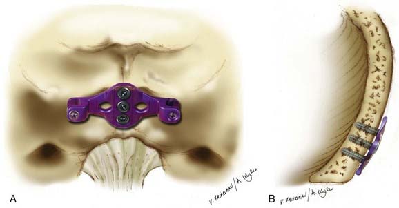
Perhaps most commonly today is placement of occipital screws that are placed either midline with special Y- or T-shaped keel plates or parasagittally in line with cervical instrumentation using eyelet connectors (Fig. 298-1). Lateral fixation has the advantage of allowing the placement of six screws and theoretically gives improved resistance to deformation because of its increased effective moment arm and bilateral purchase. Midline screw fixation allows the placement of only three screws, but uses the thicker occipital keel for longer screw purchase.41 Anderson and associates41 compared these two fixation locations in cadaveric specimens. Their small series showed that the location of fixation had only a small effect on the range of motion and was dependent on load direction. Although lateral fixation had significantly less motion in lateral bending, no other significant differences were observed. Surprisingly, the location of occipital fixation may have little influence on biomechanical properties of the fixation, and therefore, the choice of location should be based on the instability pattern and feasibility of plate fixation with the rest of the construct rather than on the specific location of fixating screws on the occiput.
Occipital Condyle Screws
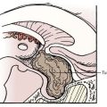
More recently, an interesting technique of occipital fixation was described separately by Uribe and coworkers49 and La Marca and colleagues.50 This technique involves screw placement into the occipital condyles, and may be particularly useful when the midline keel is not available, such as in cases of prior suboccipital craniectomy (Fig. 298-2).
Screw Fixation—C1-2
Limitations in stabilization by previous dorsal wiring techniques prompted the development of newer techniques of dorsal atlantoaxial fixations using rigid screw fixation. Although these rigid screw techniques provide significantly higher rates of fusion and less rigid postoperative immobilization, they prove to be more technically challenging due to screw placement near the path of the vertebral arteries, thus requiring the aid of intraoperative fluoroscopy and/or surgical navigation tools and detailed knowledge of the anatomy.3
Transarticular Screw Technique of Magerl
The Magerl transarticular screw technique51 proved to be a major advancement in C1-2 fixation. Although it is more technically challenging than dorsal wiring techniques, it offers two main advantages. First, it does not rely on intact posterior elements and, second, it provides immediate stabilization and increasing fusion rates of the construct due to reduction of rotatory movement from the transarticular screw.
Preoperative planning with plain x-rays and fine-cut CT scans is essential.12 Traction used to restore anatomic alignment preoperatively may foster a technically simpler procedure. Some surgeons advocate preoperative fiberoptic intubation and perioperative somatosensory evoked potentials.52 The patient’s head is fixed in pins or rested on a horseshoe head holder in the prone position. Final positioning is confirmed with real-time fluoroscopy to verify alignment of the atlantoaxial complex.
The entry point for screw placement is 2 to 3 mm lateral to and 2 to 3 mm above the medial aspect of the C2-3 facet. Recognition of the course of the vertebral artery is essential during this step. Using fluoroscopic guidance, a 2.5-mm drill bit is directed sagittally, aiming toward the anterior arch of C1. A percutaneous approach from approximately the level of C7 is required. To prevent possible anterior dislocation of C1 during screw placement, a 3.5-mm tap is used for the entire length of the trajectory, followed by insertion of a 3.5-mm fully threaded screw of the appropriate length, stopping just short of the anterior cortex of C1. After repeating the process on the contralateral side, the laminae of both C1 and C2 are decorticated and autologous iliac crest bone grafts are laid over the exposed surfaces to promote bony fusion.3 Patients are placed in a hard collar for up to 6 weeks postoperatively.
Several clinical and cadaveric studies have shown the reliability in the strength and stability of the transarticular screw construct.12 Multiple studies have documented fusion rates as high as 95.5% to 96% with the use of this technique53,54 and biomechanical cadaveric studies show the construct to not only be stable in flexion and extension, but also rotation.16,52,55,56
Complication rates have been reported as between 2% and 14% for this technique, depending on the series.16,52,55,56 The complications include screw malposition and vertebral artery injury. The risk of vertebral artery injury is well documented in the literature57 with fatalities reported from bilateral vertebral artery injuries; Madawi and associates56 reported intraoperative vertebral artery in 8.2% of their patients. Wright and Lauryssen performed a retrospective study that reported the risk of vertebral artery injury with transarticular screw fixation to be 4.1% per patient or 2.2% per screw inserted.57 The main limitation to this technique is that anatomic variation often precludes safe screw placement.
C1-C2 Rod-Cantilever Technique
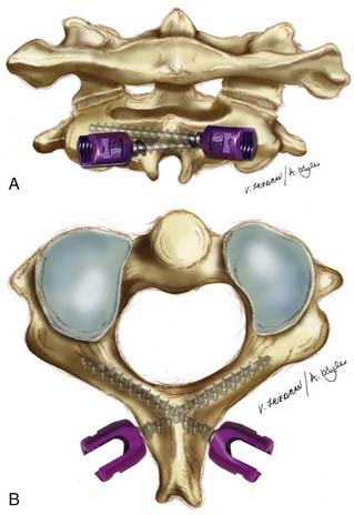
The Magerl transarticular screw technique remains a technically challenging procedure because a narrow corridor for screw trajectory needs to be maintained to traverse the C2 pedicle and C1-2 joint without injuring the vertebral artery, particularly if there is anatomic variation. These technical limitations prompted several authors to report individualization of C1 and C2 instrumentation by placing C1 lateral mass screws and C2 pedicle screws. Goel and Laheri58 described atlantoaxial fixation where C1 and C2 lateral mass screws were connected using a plate. Later, Harms and Melcher59 described C1 lateral mass screws connected to C2 pars screws using rods. This technique circumvents the limitation of anatomic variation for rigid fixation.
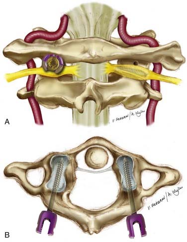
The patient is carefully placed in the prone position with use of real-time fluoroscopy to verify alignment and the position of the atlantoaxial complex. The cervical spine is exposed subperiosteally from the occiput to the level of C3-4. The C1-2 articulation is exposed similarly to the technique described in the Magerl technique. After the dorsal root ganglion of C2 is retracted inferiorly, the middle of the junction of the posterior arch of C1 and the midpoint of the inferoposterior part of the C1 lateral mass is exposed. This marks the entry point for the C1 screw, which is marked by using the high-speed bur drill to prevent slippage. The pilot hole is drilled in a straight trajectory in an anteroposterior direction, parallel to the plane of the posterior arch of C1 in the sagittal direction, directing the tip of the drill toward the anterior arch of C1. The hole is tapped, and then a 3.5-mm polyaxial screw of appropriate length is inserted into the lateral mass of C1 bicortically. An 8-mm unthreaded portion of the C1 screw remains above the lateral mass to minimize injury to the greater occipital nerve and to allow the polyaxial portion of the screw to lie above the posterior arch of C1 (Fig. 298-3).
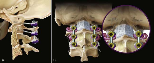
A no. 4 Penfield is used to delineate the medial border of the pars interarticularis of C2 and then the entry point for the C2 screw is made with the high-speed bur drill in the cranial and medial quadrant of the isthmus surface of C2 (Fig. 298-4). A pilot hole is made with a 2-mm bit, just perforating the opposite cortex. The direction of the bit is approximately 20 to 30 degrees in a lateral to medial and cephalad trajectory. The integrity of the pilot hole is confirmed with the ball probe. The hole is tapped, and then a 3.5-mm polyaxial screw of the appropriate length is inserted bicortically. Contoured rods are placed in the screw heads and secured in position. The exposed bone of C1 and C2 is decorticated and autologous iliac crest cancellous bone is placed over the decorticated bone. The patient is placed in a soft cervical collar for 2 to 3 weeks, postoperatively.
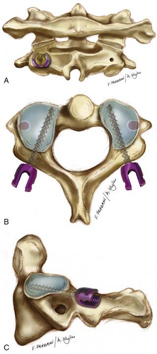
FIGURE 298-4 A, C2 pedicle screw fixation—posterior view. The entry point is depicted on the right, with the final position of the screw head on the left. The entry point is 5 mm lateral and 7 mm inferior to a point determined by the intersection of a horizontal line over the C2 lamina and a vertical line along the lateral aspect of the spinal canal.60 B, C2 pedicle screw fixation, axial view. The trajectory of the C2 pedicle screw is approximately 20 to 40 degrees in the transverse plane. This can be verified by review of preoperative axial CT imaging and intraoperatively by palpating the medial border of the C2 pedicle. C, C2 pedicle screw fixation, lateral view. The trajectory of the C2 pedicle screw is 20 degrees in the sagittal plane.
Harms and Melcher59 reported satisfactory screw placement and reduction in all 37 patients in their series. They reported no neural or vascular damage related to the technique. This technique is more widely applicable and simpler than the transarticular technique, yet some patients with narrow C2 pars or medially located foramen transversarium still pose a threat to safe screw placement.60,61
Bilateral, Crossing C2 Laminar Screws
Wright6–8 and Leonard6 described a new technique for rigid screw fixation of the axis and incorporation into atlantoaxial fixation or subaxial cervical constructs with insertion of polyaxial screws into the laminae of C2 in a bilateral, crossing fashion (Fig. 298-5). These screws are connected to C1 lateral mass screws similarly to the C1-2 rod-cantilever technique. This technique provides the benefit of allowing safe rigid fixation of C2 without placing the vertebral arteries at risk of injury. Although C1 screw placement still requires aid in visualization with fluoroscopy, the C2 screws can also be placed without fluoroscopic guidance or surgical navigation. This technique requires intact posterior elements of C2, unlike the previous techniques described.3
It is important to palpate the drilled hole before screw insertion to minimize the chance of the screw violating the canal. Intraoperative and postoperative radiographs are not predictive of proper screw placement.62 A variation of Wright’s technique as reported by Jea and associates63 involves placement of a small cortical window at the lateral aspect of the lamina, near the laminar-facet junction, to visualize the distal tip of the screw to verify that the screw has not violated the spinal canal.
In the initial series of 10 patients studied by Wright, no intraoperative or immediate postoperative complications were encountered. All C2 screws were placed satisfactorily without any technical problems during screw insertion. There were no neurological or vascular complications noted. All patients demonstrated stability on flexion-extension radiographs obtained at 6 weeks. The first two patients treated with this technique had thin-cut CT scans with sagittal and coronal reconstructions obtained at 6 months after surgery. Both patients exhibited solid arthrodesis with bridging bone from the posterior arch of C1 to the lamina of C2.32
A larger series with 20 patients with a follow-up period of at least 1 year reported 100% fusion rates and no complications.8 Other authors have subsequently published their experience with C2 laminar fixation64–67 with excellent results. Although in some cases the screws were found to violate the spinal canal, no neurological or vascular injury occurred.
Initial biomechanical testing suggests atlantoaxial stabilization with C2 translaminar screws to be equivalent to transarticular C1-2 fixation and C1-2 rod-cantilever techniques. Gorek and associates68 compared C2 translaminar screw fixation with C1-2 transarticular fixation and reported equivalent stability and Lapsiwala and associates69 concluded that C2 translaminar screws provide adequate stiffness compared with anterior and posterior transarticular screws, and C2 pedicle screws.
Conclusion
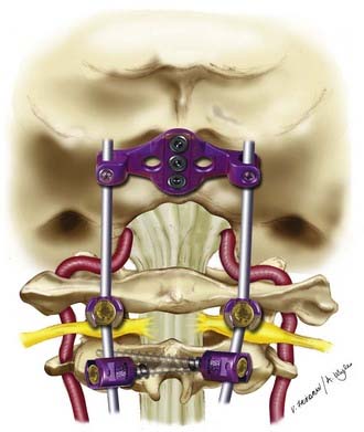
During the past decades many advancements have been made in dorsal occipitocervical and atlantoaxial fixation techniques. Earlier dorsal wiring techniques provided technical simplicity, but lower rates of successful fusion and the need for postoperative rigid immobilization. Newer rigid screw fixation techniques (Fig. 298-6) provide higher fusion rates and less rigid postoperative immobilization, but are technically more challenging. Nonetheless, the evolution of these various fixation techniques provide the surgeon with the most appropriate technique available depending on patient anatomy, surgical indication, presence of posterior elements, and ability of the surgeon.
Anderson PA, Oza AL, Puschak TJ, et al. Biomechanics of occipitocervical fixation. Spine. 2006;31:755.
Dickman CA, Douglas RA, Sonntag VKH. Occipitocervical fusion: posterior stabilization of the craniovertebral junction and upper cervical spine. BNI Q. 1990;6:2.
Dickman CA, Sonntag VK, Papadopoulos SM, et al. The interspinous method of posterior atlantoaxial arthrodesis. J Neurosurg. 1991;74:190.
DiPaola MJ, DiPaola CP, Conrad BP, et al. Cervical spine motion in manual versus Jackson table turning methods in a cadaveric global instability model. J Spinal Disord Tech. 2008;21:273.
Ebraheim NA, Lu J, Biyani A, et al. An anatomic study of the thickness of the occipital bone. Implications for occipitocervical instrumentation. Spine. 1996;21:1725.
Ebraheim N, Rollins JR, Xu R, et al. Anatomic consideration of C2 pedicle screw placement. Spine. 1996;21:691.
Goel A, Laheri V. Plate and screw fixation for atlanto-axial subluxation. Acta Neurochir (Wien). 1994;129:47.
Haher TR, Yeung AW, Caruso SA, et al. Occipital screw pullout strength. A biomechanical investigation of occipital morphology. Spine. 1999;24:5.
Harms J, Melcher RP. Posterior C1-C2 fusion with polyaxial screw and rod fixation. Spine. 2001;26:2467.
Jeanneret B, Magerl F. Primary posterior fusion C1/2 in odontoid fractures: indications, technique, and results of transarticular screw fixation. J Spinal Disord. 1992;5:464.
Lapsiwala SB, Anderson PA, Oza A, et al. Biomechanical comparison of four C1 to C2 rigid fixative techniques: anterior transarticular, posterior transarticular, C1 to C2 pedicle, and C1 to C2 intralaminar screws. Neurosurgery. 2006;58:516.
Magerl F, Seemann PS. Stable posterior fusion of the atlas and axis by transarticular screw fixation. In: Kehr P, Wiedner A, editors. Cervical Spine I. New York: Springer-Verlag; 1986:322-327.
Oda I, Abumi K, Sell LC, et al. Biomechanical evaluation of five different occipito-atlanto-axial fixation techniques. Spine. 1999;24:2377.
Pait TG, Al-Mefty O, Boop FA, et al. Inside-outside technique for posterior occipitocervical spine instrumentation and stabilization: preliminary results. J Neurosurg. 1999;90:1.
Roberts DA, Doherty BJ, Heggeness MH. Quantitative anatomy of the occiput and the biomechanics of occipital screw fixation. Spine. 1998;23:1100.
Sandhu FA, Pait TG, Benzel E, et al. Occipitocervical fusion for rheumatoid arthritis using the inside-outside stabilization technique. Spine. 2003;28:414.
Sutterlin CEIII, Bianchi JR, Kunz DN, et al. Biomechanical evaluation of occipitocervical fixation devices. J Spinal Disord. 2001;14:185.
Uribe JS, Ramos E, Vale F. Feasibility of occipital condyle screw placement for occipitocervical fixation: a cadaveric study and description of a novel technique. J Spinal Disord Tech. 2008;21:540.
Wright NM, Lauryssen C. Techniques of posterior C1-C2 stabilization. Tech in Neurosurg. 1998;4:286.
Wright NM, Lauryssen C. Vertebral artery injury in C1-2 transarticular screw fixation: results of a survey of the AANS/CNS section on disorders of the spine and peripheral nerves. American Association of Neurological Surgeons/Congress of Neurological Surgeons. J Neurosurg. 1998;88:634.
Wright NM. Posterior C2 fixation using bilateral, crossing C2 laminar screws: case series and technical note. J Spinal Disord Tech. 2004;17:158.
Wright NM. Translaminar rigid screw fixation of the axis. J Neurosurg Spine. 2005;3:409.
Zipnick RI, Merola AA, Gorup J, et al. Occipital morphology. An anatomic guide to internal fixation. Spine. 1996;21:1719.
1 Vender JR, Rekito AJ, Harrison SJ, et al. The evolution of posterior cervical and occipitocervical fusion and instrumentation. Neurosurg Focus. 2004;16:E9.
2 White AA, Panjabi MM. Clinical Biomechanics of the Spine. Philadelphia: JB Lippincott; 1978.
3 Menendez JA, Wright NM. Techniques of posterior C1-C2 stabilization. Neurosurgery. 2007;60:S103.
4 Mixter SJ, Osgood RBIV. Traumatic lesions of the atlas and axis. Ann Surg. 1910;51:193.
5 Gallie W. Fractures and dislocations of the cervical spine. Am J Surg. 1939;46:495.
6 Leonard JR, Wright NM. Pediatric atlantoaxial fixation with bilateral, crossing C-2 translaminar screws. Technical note. J Neurosurg. 2006;104:59.
7 Wright NM. Posterior C2 fixation using bilateral, crossing C2 laminar screws: case series and technical note. J Spinal Disord Tech. 2004;17:158.
8 Wright NM. Translaminar rigid screw fixation of the axis. J Neurosurg Spine. 2005;3:409.
9 Horn EM, Feiz-Erfan I, Lekovic GP, et al. Survivors of occipitoatlantal dislocation injuries: imaging and clinical correlates. J Neurosurg Spine. 2007;6:113.
10 Grob D, Schutz U, Plotz G. Occipitocervical fusion in patients with rheumatoid arthritis. Clin Orthop Relat Res. 366. 1999:46.
11 Sandhu FA, Pait TG, Benzel E, et al. Occipitocervical fusion for rheumatoid arthritis using the inside-outside stabilization technique. Spine. 2003;28:414.
12 Wright NM, Lauryssen C. Techniques of posterior C1-C2 stabilization. Tech in Neurosurg. 1998;4:286.
13 Anderson LD, D’Alonzo RT. Fractures of the odontoid process of the axis. J Bone Joint Surg Am. 1974;56:1663.
14 Scott EW, Haid RWJr, Peace D. Type I fractures of the odontoid process: implications for atlanto-occipital instability. Case report. J Neurosurg. 1990;72:488.
15 Morone M, Rodts G, Erwood S, et al. Anterior odontoid screw fixation: indications, complication avoidance, and operative technique. Contemp Neurosurg. 1996;18:1.
16 Jeanneret B, Magerl F. Primary posterior fusion C1/2 in odontoid fractures: indications, technique, and results of transarticular screw fixation. J Spinal Disord. 1992;5:464.
17 Dunn ME, Seljeskog EL. Experience in the management of odontoid process injuries: an analysis of 128 cases. Neurosurgery. 1986;18:306.
18 Hadley MN, Browner CM, Liu SS, et al. New subtype of acute odontoid fractures (type IIA). Neurosurgery. 1988;22:67.
19 Schatzker J, Rorabeck CH, Waddell JP. Fractures of the dens (odontoid process). An analysis of thirty-seven cases. J Bone Joint Surg Br. 1971;53:392.
20 Hadley MN, Dickman CA, Browner CM, et al. Acute axis fractures: a review of 229 cases. J Neurosurg. 1989;71:642.
21 Dvorak J, Panjabi MM. Functional anatomy of the alar ligaments. Spine. 1987;12:183.
22 Panjabi M, Dvorak J, Crisco JIII, et al. Flexion, extension, and lateral bending of the upper cervical spine in response to alar ligament transections. J Spinal Disord. 1991;4:157.
23 Fielding JW, Cochran GB, Lawsing JFIII, et al. Tears of the transverse ligament of the atlas. A clinical and biomechanical study. J Bone Joint Surg Am. 1974;56:1683.
24 Dvorak J, Panjabi M, Gerber M, et al. CT-functional diagnostics of the rotatory instability of upper cervical spine. 1. An experimental study on cadavers. Spine. 1987;12:197.
25 Weissman BN, Aliabadi P, Weinfeld MS, et al. Prognostic features of atlantoaxial subluxation in rheumatoid arthritis patients. Radiology. 1982;144:745.
26 Ranawat CS, O’Leary P, Pellicci P, et al. Cervical spine fusion in rheumatoid arthritis. J Bone Joint Surg Am. 1979;61:1003.
27 Reilly TM, Sasso RC, Hall PV. Atlantoaxial stabilization: clinical comparison of posterior cervical wiring technique with transarticular screw fixation. J Spinal Disord Tech. 2003;16:248.
28 Os odontoideum. Neurosurgery. 2002;50(3 suppl):S148.
29 DiPaola MJ, DiPaola CP, Conrad BP, et al. Cervical spine motion in manual versus Jackson table turning methods in a cadaveric global instability model. J Spinal Disord Tech. 2008;21:273.
30 Foerster O. Die Leitungsbahnen des Schmerzgefuhls und die Chirurgischee Behandlung der Schmerzzustande. Berlin: Urbin and Schwarzenberg; 1927.
31 Elia M, Mazzara JT, Fielding JW. Onlay technique for occipitocervical fusion. Clin Orthop Relat Res. 280. 1992:170.
32 Dickman CA, Sonntag VK, Papadopoulos SM, et al. The interspinous method of posterior atlantoaxial arthrodesis. J Neurosurg. 1991;74:190.
33 Garfin SR, Moore MR, Marshall LF. A modified technique for cervical facet fusions. Clin Orthop Relat Res. 230. 1988:149.
34 Hamblen DL. Occipito-cervical fusion. Indications, technique and results. J Bone Joint Surg Br. 1967;49:33.
35 Huhn SL, Wolf AL, Ecklund J. Posterior spinal osteosynthesis for cervical fracture/dislocation using a flexible multistrand cable system: technical note. Neurosurgery. 1991;29:943.
36 Jain VK, Takayasu M, Singh S, et al. Occipital-axis posterior wiring and fusion for atlantoaxial dislocation associated with occipitalization of the atlas. Technical note. J Neurosurg. 1993;79:142.
37 MacKenzie AI, Uttley D, Marsh HT, et al. Craniocervical stabilization using Luque/Hartshill rectangles. Neurosurgery. 1990;26:32.
38 Oda I, Abumi K, Sell LC, et al. Biomechanical evaluation of five different occipito-atlanto-axial fixation techniques. Spine. 1999;24:2377.
39 Ransford AO, Crockard HA, Pozo JL, et al. Craniocervical instability treated by contoured loop fixation. J Bone Joint Surg Br. 1986;68:173.
40 Brooks AL, Jenkins EB. Atlanto-axial arthrodesis by the wedge compression method. J Bone Joint Surg Am. 1978;60:279.
41 Anderson PA, Oza AL, Puschak TJ, et al. Biomechanics of occipitocervical fixation. Spine. 2006;31:755.
42 Hurlbert RJ, Crawford NR, Choi WG, et al. A biomechanical evaluation of occipitocervical instrumentation: screw compared with wire fixation. J Neurosurg. 1999;90:84.
43 Sutterlin CEIII, Bianchi JR, Kunz DN, et al. Biomechanical evaluation of occipitocervical fixation devices. J Spinal Disord. 2001;14:185.
44 Ebraheim NA, Lu J, Biyani A, et al. An anatomic study of the thickness of the occipital bone. Implications for occipitocervical instrumentation. Spine. 1996;21:1725.
45 Haher TR, Yeung AW, Caruso SA, et al. Occipital screw pullout strength. A biomechanical investigation of occipital morphology. Spine. 1999;24:5.
46 Roberts DA, Doherty BJ, Heggeness MH. Quantitative anatomy of the occiput and the biomechanics of occipital screw fixation. Spine. 1998;23:1100.
47 Zipnick RI, Merola AA, Gorup J, et al. Occipital morphology. An anatomic guide to internal fixation. Spine. 1996;21:1719.
48 Pait TG, Al-Mefty O, Boop FA, et al. Inside-outside technique for posterior occipitocervical spine instrumentation and stabilization: preliminary results. J Neurosurg. 1999;90:1.
49 Uribe JS, Ramos E, Vale F. Feasibility of occipital condyle screw placement for occipitocervical fixation: a cadaveric study and description of a novel technique. J Spinal Disord Tech. 2008;21:540.
50 La Marca F, Zubay G, Morrison T, et al. Cadaveric study for placement of occipital condyle screws: technique and effects on surrounding anatomic structures. J Neurosurg Spine. 2008;9:347.
51 Magerl F, Seemann PS. Stable posterior fusion of the atlas and axis by transarticular screw fixation. In: Kehr P, Wiedner A, editors. Cervical Spine I. New York: Springer-Verlag; 1986:322-327.
52 Stillerman CB, Wilson JA. Atlanto-axial stabilization with posterior transarticular screw fixation: technical description and report of 22 cases. Neurosurgery. 1993;32:948.
53 Fuji T, Oda T, Kato Y, et al. Accuracy of atlantoaxial transarticular screw insertion. Spine. 2000;25:1760.
54 Haid RWJr. C1-C2 transarticular screw fixation: technical aspects. Neurosurgery. 2001;49:71.
55 Grob D, Crisco JJIII, Panjabi MM, et al. Biomechanical evaluation of four different posterior atlantoaxial fixation techniques. Spine. 1992;17:480.
56 Madawi AA, Casey AT, Solanki GA, et al. Radiological and anatomical evaluation of the atlantoaxial transarticular screw fixation technique. J Neurosurg. 1997;86:961.
57 Wright NM, Lauryssen C. Vertebral artery injury in C1-2 transarticular screw fixation: results of a survey of the AANS/CNS section on disorders of the spine and peripheral nerves. American Association of Neurological Surgeons/Congress of Neurological Surgeons. J Neurosurg. 1998;88:634.
58 Goel A, Laheri V. Plate and screw fixation for atlanto-axial subluxation. Acta Neurochir (Wien). 1994;129:47.
59 Harms J, Melcher RP. Posterior C1-C2 fusion with polyaxial screw and rod fixation. Spine. 2001;26:2467.
60 Ebraheim N, Rollins JR, Xu R, et al. Anatomic consideration of C2 pedicle screw placement. Spine. 1996;21:691.
61 Yeom JS, Buchowski JM, Park KW, et al. Undetected vertebral artery groove and foramen violations during C1 lateral mass and C2 pedicle screw placement. Spine. 2008;33:E942.
62 Lehman RAJr, Sasso RC, Helgeson MD, et al. Accuracy of intraoperative plain radiographs to detect violations of intralaminar screws placed into the C2 vertebrae: a reliability study. Spine. 2007;32:3036.
63 Jea A, Sheth RN, Vanni S, et al. Modification of Wright’s technique for placement of bilateral crossing C2 translaminar screws: technical note. Spine J. 2008;8:656.
64 Nakanishi K, Tanaka M, Sugimoto Y, et al. Posterior cervical spine arthrodesis with laminar screws: a report of two cases. Acta Med Okayama. 2007;61:115.
65 Sciubba DM, Noggle JC, Vellimana AK, et al. Laminar screw fixation of the axis. J Neurosurg Spine. 2008;8:327.
66 Wang MY. C2 crossing laminar screws: cadaveric morphometric analysis. Neurosurgery. 2006:59-ONS84.
67 Wang MY. Cervical crossing laminar screws: early clinical results and complications. Neurosurgery. 2007;61:311.
68 Gorek J, Acaroglu E, Berven S, et al. Constructs incorporating intralaminar C2 screws provide rigid stability for atlantoaxial fixation. Spine. 2005;30:1513.
69 Lapsiwala SB, Anderson PA, Oza A, et al. Biomechanical comparison of four C1 to C2 rigid fixative techniques: anterior transarticular, posterior transarticular, C1 to C2 pedicle, and C1 to C2 intralaminar screws. Neurosurgery. 2006;58:516.