[level-membership-for-orthopaedics-category]
28 Occipital-Cervical and Upper Cervical Spine Fractures
Anatomy
Occipital Bone
The occipital bone is an anteriorly concave bone that forms the base of the cranium. The occipital condyles are paired kidney-shaped structures that form the base of the occipital bone and are the structural bases for the articulation of the skull with the cervical spine. This articulation is mainly formed by the atlanto-occipital joint, a paired synovial joint composed of the bilateral occipital condyles projecting inferiorly to articulate with the concave lateral masses of the atlas. The atlas, in turn, articulates with the axis anteriorly via the odontoid process, and laterally via the lateral masses, with associated synovial capsules at each articulation.1
Ligaments of the Craniocervical Junction
The bony anatomy of the skull base, occipital condyles, atlas, axis, and odontoid process is of obvious importance in understanding biomechanical stability, fracture patterns, and surgical planning. The anatomy of the ligamentous structures of the craniocervical junction and upper cervical spine is also of crucial importance in maintaining biomechanical stability of the region, where injury to ligamentous structures can dramatically alter management of bony fractures. The nuchal ligament runs dorsally over the occiput and upper cervical spine, from the inion to the spinous processes of the cervical vertebrae. The ligamentum flavum runs underneath the laminae and projects superiorly to the base of the occiput. The anterior longitudinal ligament (ALL) has a dense arrangement of fibers and projects from the anterior tubercle of the axis inferiorly along the ventral surface of each cervical vertebral body. The anterior atlanto-occipital membrane, the superior extension of the ALL, is superficial, more loosely arranged, and connects the basilar part of the occiput to the atlas. The posterior longitudinal ligament runs along the dorsal surface of the cervical vertebral bodies and projects superiorly as the tectorial membrane, attaching to the skull base. The alar ligaments (attaching to the odontoid process, occipital condyles, and atlas), apical ligament (attaching the odontoid process to the clivus), and transverse atlantal ligament (restricting the odontoid to the anterior arch of the atlas) play a key role in maintaining the anatomic relationship of the odontoid process, the atlas, and the foramen magnum. Given the significant range of flexion-extension at O-C1 and rotation at C1-2, and the critical importance of the underlying neurovascular structures, biomechanical instability of this region can present with severe disability and must be treated aggressively.
Injuries of the Craniocervical Junction
Occipital Condyle Fractures
Occipital condyle fractures can be classified into three main types according to the Anderson and Montesano scheme.2 These fractures are seen in 1% to 3% of cases of blunt trauma to the craniocervical region. Type 1 fractures usually result from axial loading injuries and are comminuted. Type II fractures are linear fractures that originate in the squama of the occipital bone and extend into the condyle. Type III fractures are avulsion fractures of the condyles; these fractures are most prone to instability and atlanto-occipital dislocation.
C1 Fractures and Transverse Ligament Injuries
Fractures of the atlas are usually defined in relation to the lateral mass and extent of arch involvement.3 They can involve any parts of the ring in isolation or in combination, ranging from single unilateral fractures to burst-type fractures involving all four aspects, which is known as a Jefferson fracture. Since isolated atlas fractures without ligamentous injury are stable and heal with simple immobilization, the clinical importance of fractures of the atlas is to understand the possible involvement of the transverse ligament, the vertebral artery, and other associated spinal fractures. The most commonly cited radiographic criteria indicating unstable disruption of the transverse ligament include the Rule of Spence4 (lateral displacement of C1 lateral masses over C2 greater than 6.9 mm) and the atlantodental interval being greater than 3 mm. However, when feasible, this author prefers MRI evaluation of all atlas fractures to assess for concomitant ligamentous injury. Transverse ligament disruption, as with other cases of atlantoaxial instability, is an indication for surgical fixation.
C2 Fractures
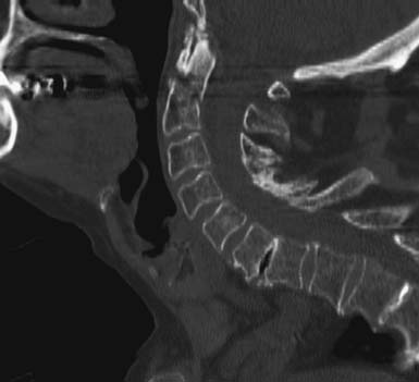
Odontoid process fractures affect the elderly far more often than younger people and are, unfortunately, relatively common. The most common classification scheme for fractures of C2, the Anderson and D’Alonzo scheme,5 relies on the location of the fracture line within the odontoid process or body of C2. In this scheme, type I fractures involve the tip of the dens, type II fractures run through the junction of the dens and the body of C2, and type III fractures course through the vertebral body of C2.
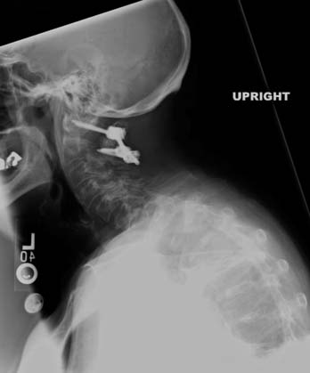
Type II fractures (Figure 28-1) are the most common type of dens fracture and are more often subject to nonunion, especially in patients older than 50 years of age when displacement is greater than 5 mm. When choosing treatment strategies for type II odontoid fractures, the surgeon must consider the integrity of the transverse ligament, age and orientation of the fracture, displacement and/or angulation of the fractured process, and patient-specific factors such as medical comorbidities, and body habitus. For example, certain body habitus features, such as a barrel chest, can make anterior odontoid screw placement impossible.
Fractures of the C2 pedicles (also known as traumatic spondylolisthesis or hangman’s fractures) are often classified based on the mechanism of injury,6,7 where flexion (type III) and flexion-distraction (type IIa) are often unstable and require surgical fixation, especially type IIa injuries with greater than 4 mm distraction and/or greater than 11 degrees of angulation. Other fractures of the axis can include isolated fractures of the C2 vertebral body or fractures of the C2 spinous process or lamina, which are usually stable and can achieve good union with nonoperative immobilization.
Craniocervical Manifestations of Rheumatoid Arthritis
Between 10% and 85% of patients with rheumatoid arthritis (RA) have neck pain and 10% to 60% have neurological deficits.8 Spinal column manifestations of RA are most often seen at the craniocervical junction. This is usually a late finding in the disease course; therefore, a significant proportion of RA patients with craniocervical abnormalities are elderly.
RA of the upper cervical spine, similar to RA in peripheral joints, is an inflammatory condition that results in degenerative synovitis, ligament laxity, pannus formation, and bony erosion. These pathological changes can lead to atlantoaxial subluxation and are present in up to 86% of patients with RA. 8RA can also lead to degeneration of the occipital condyle-C1 joints, leading to cranial settling. Degeneration of the C1-2 and O-C1 joints can also lead to vertical migration of the odontoid process into the foramen magnum (basilar invagination), resulting in myelopathy from odontoid compression of the lower brainstem. Myelopathy can also be caused by pannus formation around the dens and consequent narrowing of the spinal canal.
Surgical Approaches and Techniques
Occipitocervical Fusion
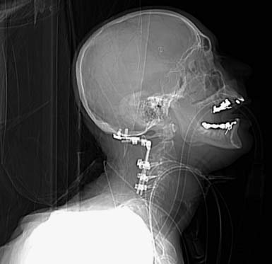
The instrumented technique for achieving rigid fixation across the occipitocervical junction was popularized by Ransford and colleagues in 1986. They described the use of a contoured steel loop and sublaminar wiring to establish a fairly rigid fixation across the OC junction. Although the use of sublaminar wires increases the risk of injury to neural structures when compared to uninstrumented, onlay fusion procedures, the vast improvement in fusion rates after sublaminar wiring popularized its use. However, in spite of the improved level of fixation after sublaminar wiring, patients still required the use of halo vests before complete solid fusion could be established. The desire for fixation techniques that obviate the need for halo vests led to the techniques being used today. The most common surgical treatment for OC instability today involves the use of a contoured occipital plate that is connected by a rod to cervical screws (Figure 28-2).
Odontoid Screw
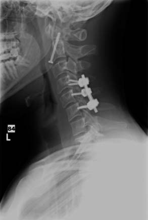
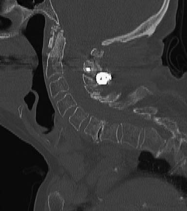
When feasible, an excellent option for treatment of type 2 odontoid fractures is direct fixation of the fracture with an anterior odontoid screw (Figure 28-3). Preoperative considerations include intact transverse ligament, fracture line orientation, and acuity of injury (given concern for nonunion with sclerotic fracture edges). Depending on displacement of the fractured odontoid process, reduction can be first achieved with external immobilization prior to, or at the time of, surgery.
C1-2 Harms
C1 lateral mass-C2 pars/pedicle screw fixation, known as the Harms construct9, is an effective posterior fusion construct for appropriately selected patients, and, unlike an odontoid screw, it can be utilized in patients with a disrupted transverse ligament. Advantages include direct visualization of fusion surfaces, flexibility in timing of surgery (can be utilized in acute and chronic treatment of instability), and, as a polyaxial screw and rod construct, it can easily be extended to the occiput or subaxial spine, if necessary.
The superolateral quadrant of the C2 lateral mass is the approximate entry point for a C2 pedicle screw. The screw is placed with a medial and cephalad trajectory (about 30 degrees in each plane). A C2 pars screw is an alternative to the pedicle screw; it is very similar but has a more inferior and medial entry point and thus has a steeper cephalad trajectory and less medial trajectory. It is essential that preoperative CT scans be studied carefully, as there is a high variability in the position and course of the vertebral arteries in this area.
C1-2 Transarticular Screws
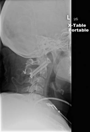
An alternative method for posterior atlantoaxial fixation is a C1-2 transarticular screw construct (Figure 28-4), where an appropriatelysized lag screw traverses the pars interarticularis of C2, the atlantoaxial joint, and the lateral mass of C1. The indications for its use and its biomechanical stability are similar to C1-2 posterior fixation screw-rod constructs.
C2 Laminar Screws
In 2004, Wright and Leonard reported a case series of C2 fixation using crossing laminar screws at C2 (Figures 28-5 and 28-6). Since then, the C2 laminar screw has emerged as a viable alternative to C2 pedicle/pars screws and C1/2 transarticular screw techniques. The growth of this technique can be attributed to ease of placement, lower incidence of vertebral artery injury, and a similar biomechanical profile when compared to C2 pedicle/pars or C1-2 transarticular screw placement.
Complications
Injuries to the occipital-cervical region are associated with significant morbidity and mortality. Most often, death is due to neurologic injury or cerebrovascular insufficiency. The risk of death or serious morbidity is higher if instability is missed or the diagnosis is delayed. With appropriate management, nonunion of bony injuries is uncommon, except for type II odontoid fractures.
1. Jackson R.S., Banit D.M., Rhyne A.L., Darden B.V. Upper cervical spine injuries. J. Am. Acad. Orthop. Surg.. 2002;10(4):271-280.
2. Anderson P.A., Montesano P.X. Morphology and treatment of occipital condyle fractures. Spine. 1988;13:731-736.
3. Landells C.D., Van Peteghem P.K. Fractures of the atlas: classification, treatment and morbidity. Spine. 1988;13:450-452.
4. Spence K.F., Decker S., Sell K.W. Bursting atlantal fracture associated with rupture of the transverse ligament. J. Bone Joint Surg. Am.. 1970;52:543-549.
5. Anderson L.D., D’Alonzo R.T. Fractures of the odontoid process of the axis. J. Bone Joint Surg. Am.. 1974;56:1663-1674.
6. Effendi B., Roy D., Cornish B., Dussault R.G., Laurin C.A. Fractures of the ring of the axis: a classification based on the analysis of 131 cases. J. Bone Joint Surg. Br.. 1981;63:319-327.
7. Levine A.M., Edwards C.C. The management of traumatic spondylolisthesis of the axis. J. Bone Joint Surg. Am.. 1985;67:217-226.
8. Pellicci P.M., Ranawat C.S., Tsairis P., Bryan W.J. A prospective study of the progression of rheumatoid arthritis of the cervical spine. J. Bone Joint Surg. Am.. 1981;63 (A):342-350.
9. Harms J., Melcher R.P. Posterior C1-C2 fusion with polyaxial screw and rod fixation. Spine. 2001;26(22):2467-2471.
[/level-membership-for-orthopaedics-category][not-level-membership-for-orthopaedics-category]
28 Occipital-Cervical and Upper Cervical Spine Fractures
Anatomy
Occipital Bone
The occipital bone is an anteriorly concave bone that forms the base of the cranium. The occipital condyles are paired kidney-shaped structures that form the base of the occipital bone and are the structural bases for the articulation of the skull with the cervical spine. This articulation is mainly formed by the atlanto-occipital joint, a paired synovial joint composed of the bilateral occipital condyles projecting inferiorly to articulate with the concave lateral masses of the atlas. The atlas, in turn, articulates with the axis anteriorly via the odontoid process, and laterally via the lateral masses, with associated synovial capsules at each articulation.1
Ligaments of the Craniocervical Junction
The bony anatomy of the skull base, occipital condyles, atlas, axis, and odontoid process is of obvious importance in understanding biomechanical stability, fracture patterns, and surgical planning. The anatomy of the ligamentous structures of the craniocervical junction and upper cervical spine is also of crucial importance in maintaining biomechanical stability of the region, where injury to ligamentous structures can dramatically alter management of bony fractures. The nuchal ligament runs dorsally over the occiput and upper cervical spine, from the inion to the spinous processes of the cervical vertebrae. The ligamentum flavum runs underneath the laminae and projects superiorly to the base of the occiput. The anterior longitudinal ligament (ALL) has a dense arrangement of fibers and projects from the anterior tubercle of the axis inferiorly along the ventral surface of each cervical vertebral body. The anterior atlanto-occipital membrane, the superior extension of the ALL, is superficial, more loosely arranged, and connects the basilar part of the occiput to the atlas. The posterior longitudinal ligament runs along the dorsal surface of the cervical vertebral bodies and projects superiorly as the tectorial membrane, attaching to the skull base. The alar ligaments (attaching to the odontoid process, occipital condyles, and atlas), apical ligament (attaching the odontoid process to the clivus), and transverse atlantal ligament (restricting the odontoid to the anterior arch of the atlas) play a key role in maintaining the anatomic relationship of the odontoid process, the atlas, and the foramen magnum. Given the significant range of flexion-extension at O-C1 and rotation at C1-2, and the critical importance of the underlying neurovascular structures, biomechanical instability of this region can present with severe disability and must be treated aggressively.
Injuries of the Craniocervical Junction
Occipital Condyle Fractures
Occipital condyle fractures can be classified into three main types according to the Anderson and Montesano scheme.2 These fractures are seen in 1% to 3% of cases of blunt trauma to the craniocervical region. Type 1 fractures usually result from axial loading injuries and are comminuted. Type II fractures are linear fractures that originate in the squama of the occipital bone and extend into the condyle. Type III fractures are avulsion fractures of the condyles; these fractures are most prone to instability and atlanto-occipital dislocation.
C1 Fractures and Transverse Ligament Injuries
Fractures of the atlas are usually defined in relation to the lateral mass and extent of arch involvement.3 They can involve any parts of the ring in isolation or in combination, ranging from single unilateral fractures to burst-type fractures involving all four aspects, which is known as a Jefferson fracture. Since isolated atlas fractures without ligamentous injury are stable and heal with simple immobilization, the clinical importance of fractures of the atlas is to understand the possible involvement of the transverse ligament, the vertebral artery, and other associated spinal fractures. The most commonly cited radiographic criteria indicating unstable disruption of the transverse ligament include the Rule of Spence4 (lateral displacement of C1 lateral masses over C2 greater than 6.9 mm) and the atlantodental interval being greater than 3 mm. However, when feasible, this author prefers MRI evaluation of all atlas fractures to assess for concomitant ligamentous injury. Transverse ligament disruption, as with other cases of atlantoaxial instability, is an indication for surgical fixation.
[/not-level-membership-for-orthopaedics-category]
