Oblique lateral radiography
Introduction
Oblique lateral radiographs are extraoral views of the jaws that can be taken using a dental X-ray set (see Fig. 12.1). Before the development of panoramic equipment they were the routine extraoral radiographs used both in hospitals and in general practice. In recent years, their popularity has waned, but the limitations of panoramic radiographs (see Ch. 15) have ensured that oblique lateral radiographs still have an important role.
Main indications
The main clinical indications for oblique lateral radiographs include:
• Assessment of the presence and/or position of unerupted teeth
• Detection of fractures of the mandible
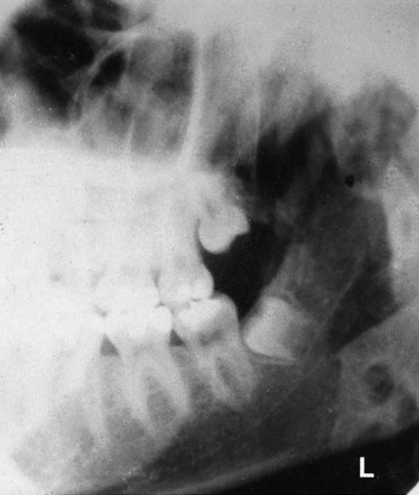
• Evaluation of lesions or conditions affecting the jaws including cysts, tumours, giant cell lesions, and other bone lesions
• As an alternative when intraoral views are unobtainable because of severe gagging or if the patient is unable to open the mouth or is unconscious (see Ch. 8, Fig. 8.1)
• As specific views of the salivary glands or temporomandibular joints.
Equipment required
This includes (see Fig. 12.3):
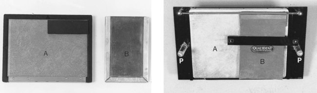
• An extraoral cassette containing film and intensifying screens or a digital phosphor plate (usually 13 × 18 cm)
• A lead shield to cover half the cassette when taking bimolar views.
Specially constructed angle boards, as shown in Fig. 12.3B, can be used to facilitate positioning, but are not considered necessary by the authors.
Basic technique principles
Patient’s head position
The patient is normally seated upright in the dental chair and is then instructed to:
1. Rotate the head to the side of interest. This is done to bring the contralateral ramus forwards, avoiding its superimposition and to increase the space available between the neck and shoulder in which to position the X-ray set.
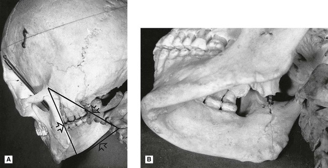
2. Raise the chin. This is done to increase the triangular space between the back of the ramus and the cervical spine (the so-called radiographic keyhole, see Fig. 12.4) through which the X-ray beam will pass.
X-ray tubehead position
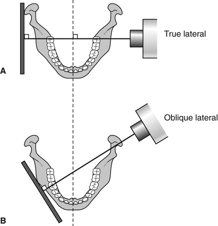
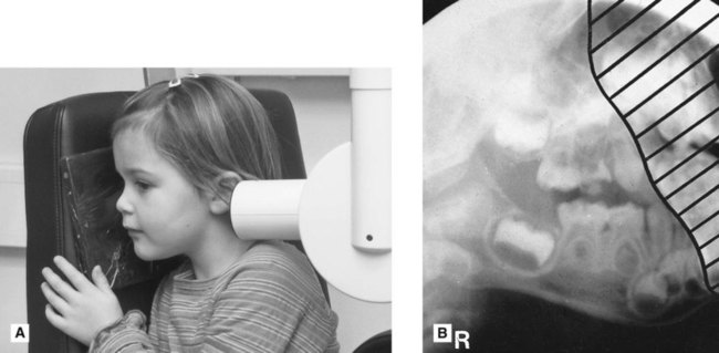
• Behind the ramus aiming through the radiographic keyhole. The X-ray tubehead is positioned along the line of the occlusal plane, just below the ear, behind the ramus aiming through the radiographic keyhole at the particular maxillary and mandibular teeth under investigation. The view from this position is illustrated in Fig. 12.4A. As shown, the X-ray beam will not pass directly between the contact areas of the posterior teeth. This may result in some overlapping of the crowns.
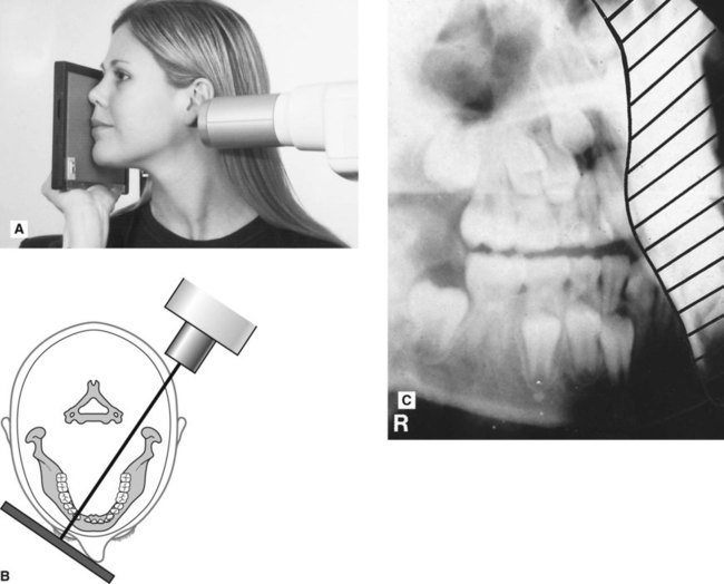
• Beneath the lower border of the mandible. The X-ray tubehead is positioned beneath the lower border of the contralateral body of the mandible, directly opposite the particular mandibular teeth under investigation, aiming slightly upwards. The view from this position is illustrated in Fig. 12.4B. As shown, the X-ray beam will now pass between the contact areas of the teeth. However, there will still be some distortion of the image in the vertical plane owing to the upward angulation of the X-ray beam. In addition, the shadow of the body of the mandible will be superimposed over the maxillary teeth.
Once these principles are understood, the technique becomes straightforward and can be modified readily for different anatomical regions and clinical situations.
Positioning examples for various oblique lateral radiographs
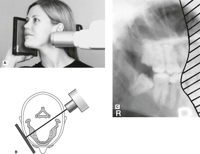
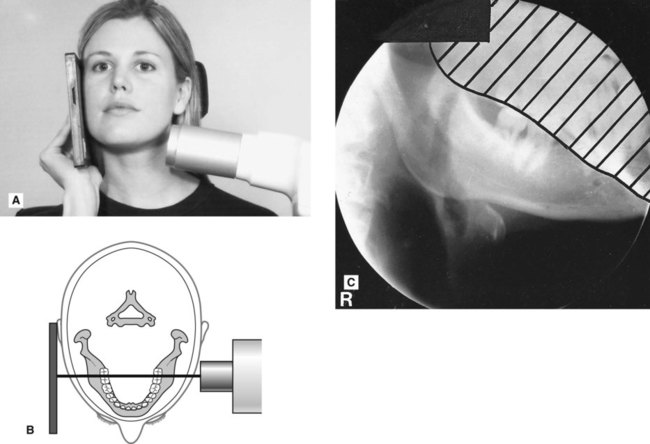
Examples of the required positioning for different oblique laterals and the resultant radiographs are shown in Figs 12.5–12.8. Illustrations show the positioning for both adults and children.
Important points to note
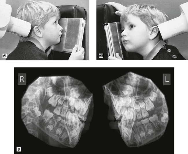
• For stability, a small child is usually rotated through 90° in the chair, so the shoulder is supported and the cassette and head can be rested on the headrest.
• The area under investigation determines the position of the cassette and the X-ray tubehead.
• An X-ray request for an oblique lateral must specify the exact region of the jaws required.
Bimolar technique
As mentioned earlier, bimolar is the term used for the radiographic projection showing oblique lateral views of the right and left sides of the jaws on the different halves of the same radiograph as shown in Fig. 12.9.
The technique can be summarized as follows:
1. The patient is positioned with one side of the face in the middle of one half of the cassette, with the nose towards the midline. The precise positioning depends on which teeth or area of the jaws are being examined (like any other oblique lateral).
2. The other half of the cassette is covered by a lead shield to prevent exposure of this side of the image receptor.
3. The X-ray tubehead is positioned to show the desired area, and the exposure is made.
4. The lead shield is then placed over the other side of the cassette to protect the part of the film already exposed.
5. The patient is then positioned in a similar manner with the cassette held on the other side of the face.
6. The X-ray tubehead is re-positioned and a second exposure made.
To access the self assessment questions for this chapter please go to www.whaitesessentialsdentalradiography.com