13 Modern Principles of Brachytherapy Physics
From 2-D to 3-D to Dynamic Planning and Delivery
Brachytherapy is now a century old. It has grown through many generations and evolved into a very efficient and uniform way to deliver radiation to tumors. A complete week, with approximately 30 hours of lectures, was devoted to cover physics and the technical aspects of brachytherapy at the American Association of Physicists in Medicine (AAPM) Summer School in 2005. The book1 about this event certainly represents one of the most comprehensive reviews of the field, and many textbooks and thousands of scientific papers have also been devoted to this topic. Nevertheless, the majority of the concepts reported in the literature were developed in a different era, when three-dimensional (3-D) imaging was limited and dose planning was based on “systems” that tried to prevent hot spots and suboptimal dose distributions in the absence of other safeguards. Clearly, many of the paradigms of brachytherapy deserve to be revisited.
Why 3-D in Brachytherapy?
Many treatment centers have reported the practical and clinical benefits of 3-D planning after transitioning from 2-D to 3-D. As demonstrated by several studies, in the case of gynecologic treatments, much higher bladder and rectal doses are found when using the CT information. The minimum dose (Dmin) to the cervix target volume is lower than the dose to point A in each case. Similarly, dose to normal tissue is generally reduced and smaller volume is irradiated when 3-D planning is introduced. Image fusion of CT and MRI data enabled improved target volume definition in 3-D–based planning.2
CT-based planning allows for some automation in the anatomy delineation and catheter definition. For instance, automatic catheter reconstruction in prostate HDR treatment can easily be achieved.3 The time required for the catheter reconstruction process using an autoreconstruction method is significantly reduced compared with the manual approach on CT, and is reduced even more when compared with film-based reconstruction.
Radiation Sources and Dose Calculation
This section is not intended to replace a radiation physics course. For that purpose, we refer the reader to an excellent book by Baltas et al.,4 which goes into much more detail or the handbook published by Mayles et al.5 We will, however, recall the basic concepts necessary to introduce modern brachytherapy radiation sources and dosimetric concepts. In particular, this should help the reader to relate known quantities such as kerma and dose to the AAPM Task Group 43 (TG43) formalism.6 Note that in this chapter, our interest is with photon-emitting sources.
Radioactivity and Interactions
Thus, after a period of time t, the remaining number of atoms, Nt, is given by:
where λ is the radioactive decay constant (probability to undergo a nuclear transformation per unit of time) and N0 the initial number of atoms. The half-life,  corresponds to the time necessary for one half of the initial number of atoms to decay or N = N0/2. It also corresponds to half of the initial activity. Solving equation 1, one finds:

Defining A0 as λ N0, one can also predict the activity at time t:

where NA is the Avogadro constant and M is molar mass. The right term of that equation applies to a pure isotope.

in which A is the atomic mass number and NA is the Avogadro constant. For photon sources, the relevant interactions are Compton, photoelectric, Rayleigh, and pair production, although for most modern brachytherapy sources, this last process is negligible. Each one has its own cross-section, which are combined to give the linear or mass attenuation coefficients (total cross section).
Dosimetry
in which dEtr is the average transferred energy, µtr/ρ is the mass energy transferred coefficient and ψ is the energy fluence (related to the photon fluence as previously defined). Note that the mass energy transferred coefficient is related to the mass attenuation coefficient through the fraction of the total energy (E) that is transferred per unit of path length.
in which µen/ρ (or µab/ρ) is the mass energy absorption coefficient and g is the mean fraction of energy not spent in collision with orbital electrons. In the context of charge particle equilibrium, the dose (D) is equal to the Kcoll and thus can be related to the photon fluence and energy fluence.
in which fas is a factor correcting for attenuation and scattering when the air around the equilibrium mass is replaced by water (adopting the notion of Baltas et al.4). In a more compact form, this equation can be written as:
Average mass energy absorption coefficient can also be used based on the effective source energy. Note that the ratio of the mass energy absorption coefficient is sometime referred to as the factor (fmed).7
Source Specification and Air Kerma Strength
The distance r must be large enough compared with the extent of the source so that it can be treated as a point source. The indices δ in the air-kerma rate was included in the revised TG43 publication8 to remove very low-energy photons produced close to the surface of the capsule or source cladding. These do not contribute to the dose beyond the first millimeter. The use of δ is similar to that of the air-kerma rate constant, γδ, as defined by the International Commission on Radiation Units and Measurements (ICRU). Values of γδ for the most commonly used isotopes can be found here.9 The SI unit for the air-kerma strength is cGycm2h−1 (µGym2h−1). The symbol U is also commonly used in practice and publications, but it is not an SI unit. At a distance (r) of 1 cm, the air-kerma strength of a perfect point source will give a dose rate in cGy/h in air. The air-kerma strength can be related to the apparent activity of a source by the air-kerma rate constant (we are not advocating the use of apparent activity):

For a PSI, the integration from t = 0 to infinity of equation 21 is a constant related to the source half-life, and the total deposited dose is given by:
Revised TG43 Formulation
By definition, equation 26 results in gX(r = r0) = 1. Thus, the variation in the radial dose function is given relative to that reference point. The removal from this equation of the geometric dependence and any variation in θ also has to be taken into account, as we describe later in this chapter. The radial dose function gX(r) is obtained as function of r from measurements or more commonly by the Monte Carlo calculation. The 1-D or 2-D values are extracted using the corresponding point source or line source geometric function. The values are tabulated and used in treatment planning.
To conclude this section, let us summarize by providing the possible revised TG43 equations:
Equations 28 and 29 are recommended. Note that the first 1-D formulation uses the line source geometric factors and radial dose function. This is the recommended 1-D formulation by the AAPM TG43 because it provides the greatest accuracy at small distances for sources that are not perfect point sources. It is, however, not systematically implemented in commercial planning systems. A source can be considered as a point source for distances more than three times the active length of the source (r > 3L). The second 1-D formulation uses the point source approximation for the geometric factor. This is the 1-D formulation used in most planning systems at this time. Historically, there was also a 1-D formulation that averaged the anisotropy factor not only over all angles, but also over all distances to obtain the anisotropy constant ψan.
Clinical Considerations
Modern Brachytherapy Photon Sources
A number of isotopes have been used throughout the years for cancer treatments. Examples are given in Table 13-1. For radiation protection (safety) reasons, a number of nuclides are not used anymore, such as radium, which has a very long half-life and emits high-energy photons. Furthermore, high-energy sources have a large mean path length. Although this generates relatively uniform dose in the target volume, the penetrating photons are a disadvantage for the protection of OARs compared with the low-energy sources, such as iodine 125 (125I) for example.
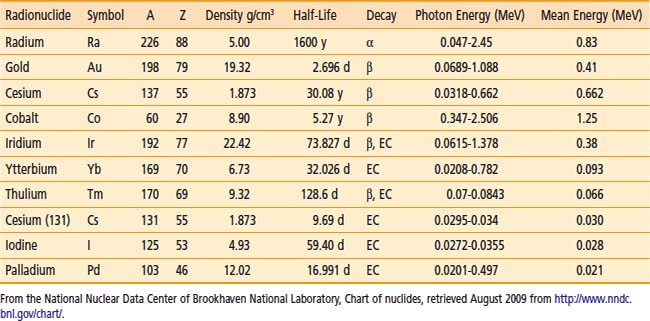
Thus, to produce sources that are easier to handle, to shield, and to subsequently dispose of, the industry has moved toward lower-energy and shorter-half-life isotopes. All the nuclides shown in the bottom portion of Table 13-1 are good examples of isotopes used in modern brachytherapy. For permanent prostate interstitial brachytherapy, the patient body itself constitutes enough shielding, in the energy range of 20 to 30 keV, that the patient is not a danger to his family (even though the “as-low-as-reasonably-achievable [ALARA] principle recommends not to hold small children directly on one’s lap for an extended period). The half-value layer of lead needed for 125I photons is 0.025 mm. The latest incarnation of this trend is unequivocally the electronic sources. The latter are miniature x-ray generators, which produce no radiation when the current is off and are sufficiently low-energy to be used in a regular radiology suite.
Permanent Seed Implants
In PSIs, multiple sources or seeds are used. The exact number and their positions within the treatment volume are the results of the planning process. It depends on the prescription dose, the seed strength, and the treatment volume. In this type of treatment, the seeds are left permanently, as the name describes, within the human body. Thus the radioisotopes are encapsulated in a biocompatible shell. Three radioisotopes are used clinically in PSI: 125I, palladium 103 (103Pd) and more recently cesium 131 (131Cs). According to the brachytherapy source register at the RPC,10 16 seed models meet the general AAPM dosimetric prerequisites at this time. For most seed models, the shells or capsules are made of titanium (Ti), a well-known material in the medical field. All clinically used seeds are between 4.5 and 5 mm in physical length and 0.8 mm in diameter. The shell is usually laser-welded at the tips of the capsules. This can have an affect on the anisotropy function of the seed resulting from the extra attenuation of photon exiting through the welding. Encapsulation provides protection to body tissues or fluids, which are never in direct contact with the radioisotopes. Therefore, the seeds can be used in patients that have allergies to iodine, for example. Furthermore, the Ti melting point is 1941 K. Therefore, they are highly resistant to all types of sterilization procedures and to cremation as well, should a patient die within a few months after the implants are placed.
Three very different designs are portrayed in Fig. 13-1. The first (left) is a 125I seed. The radioactive material is deposited on a silver rod (red) in a welded Ti capsule (black). This design is typical of the 6711 seed and of the SelectSeed. The total seed length is 4.5 mm for both models. The middle seed is model 2335 103Pd seed. The radioactive material is deposited on three polymer beads (red) on each side of a 1.2-mm long tungsten marker (yellow). A welded, double-wall Ti capsule is used (black) to seal the components. The total seed length is 5 mm (4.25 mm active length). Finally, the last design represented is the IBt OptiSeed 1031L 103Pd seed. The innovative part of this seed is its biocompatible polymer shell made only of carbon and hydrogen (orange). A 2-mm long gold marker (yellow) is placed in the middle of the 5-mm long seed. On each side of the marker, a palladium tube (red) 0.7 mm in length emits the low-energy photons. The active length is 3.7 mm.
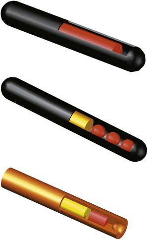
FIGURE 13-1 • A Monte Carlo study of seed design on the interseed attenuation in permanent prostate implants.
(From Afsharpour H, D’Amours M, Coté B, et al: A Monte Carlo study on the effect of seed design on the interseed attenuation in permanent prostate implants, Med Phys 35:3671, 2008.)
Let us stress that many more designs exist.11 Because of the internal configuration of the marker and nuclides, and the use of different marker and encapsulation materials, it should be obvious to the reader that each seed will have specific photon emission patterns: intensity as a function, polar angles, and energy spectrum. Therefore, we emphasize once more, that TG43 dosimetric parameters are different for each seed.
Iodine 125
The half-life and photon energies are given in Table 13-1. The specific activity of 125I is more than 600 GBq/mg4 and iodine seeds are currently being used not only for PSIs (with air-kerma strength between 0.4 U to 0.8 U) but also eye plaque (up to 5 U).
Cesium 131
 = 11.50 days). 131Cs also proceeds by EC in 131Xe with a half-life of 9.69 days. This last process results in low-energy x-rays between 29.46 keV and 34.42 keV. There is no gamma emission.
Note that this isotope possesses the shortest half-life of the three isotopes available for PSI. Thus the initial dose rate for 131Cs is higher than that of 103Pd and 125I.13,14 It is thus more susceptible to postimplant edema. Finally, the controversies remain in comparing the dose to both the prostate and the OARs with different radionuclides, in particular when the biologic effective dose is considered.15
High-Dose-Rate and Pulsed-Dose-Rate Brachytherapy
Ytterbium 169
Battista et al.16 have proposed ytterbium 169 (169Yb) as an alternative radionuclide for brachytherapy. Its specific activity is approximately 2.5 times higher than 192Ir, making it a good candidate for production of a small source of high strength. With an average energy of 93 keV, 169Yb would lower the shielding requirements of an HDR brachytherapy room. This nuclide is produced in a reactor from the reaction 168Yb(n,γ)169Yb. Because 169Yb composes only 0.13% of natural Yb element, an enrichment process must be performed. 169Yb decays by EC in excited states thulium 169 (169Tm). Return to the ground state proceeds via gamma emissions (45%) or internal conversion (55%). Seventy-four γ-ray transitions (from 63 keV to 782 keV), 13 characteristic x-rays, and more than 100 different electron energies (the most probable all being less than 130 keV) are emitted. The most common γ-rays are 63.12 keV (44%), 109.8 keV (17.5%), 130.5 keV (11.3%), 177.2 keV (22.2%), 198 keV (35.8%), and 307.7 keV (10%). A potential downside of this isotope from a clinical perspective is that its half-life is less then 50% of that of 192Ir, and it therefore needs more frequent source change.
Thulium 170
This radioisotope is made by neutron activation through the reaction 169Tm(n,γ)170Tm. The abundance of stable 169Tm is 100%. 169Tm is the rarest of the rare-earth elements (although found in quantities similar to silver) composing less than 0.01% of the ores from which it is extracted.17 Thus obtaining high purity materials is expensive. The decay of 170Tm proceeds mainly (99.87%) via β− decay. It can decay directly to the ground state (81.6% of the time) with a maximum beta energy of 968 keV (average energy of 323 keV). 18.3% of time the β− decay will go to the first excited state and the associated beta energy will be lower (maximum of 883 keV, average of 290.5 keV). Final decay to the ground state can proceed directly by gamma emission of 84.25 keV photons, 2.48% of the time or via internal conversion leading to a series of six x-rays and six low-energy electrons. Apart from the 84.25 keV, the total x-ray emission probability is small at 6.25% for energies ranging from 7.42 keV (2.93%) to 60.96 keV (0.12%).
However, it should be noted that because of the low gamma and x-ray emission intensities, the air-kerma rate constant for 170Tm is approximately 200 times lower than 192Ir.9 Thus, a thulium source might very well be limited to PDR applications. Moreover, the effect of the high-energy electron emitted in beta decay probably needs to be taken into account both in terms of bremsstrahlung emission18 and also in terms of the possibility of insufficient encapsulation thickness to stop all betas. In such a case, an increased dose could be expected in the first few mm outside of the source capsule.
Electronic Sources
The latest in the field of brachytherapy are electronic sources.19 These are composed of a miniature x-ray source, which emits x-ray only when the tube current is on. Xoft has commercialized the first electronic sources, Axxent, and these are Food and Drug Administration–approved for specific treatments. It is a low-energy source of 50 kV. As such, the dose fall-off is greater with electronic sources than 192Ir. Because the energy is lower than current radiology type devices, the body itself constitutes sufficient shielding. This allows for treatment personnel to be present in the room with the patient during treatment. So in principle no special (shielded) treatment room is needed. Finally, there is no radioactive waste handling.
As with any x-ray device, an electronic brachytherapy source produces a continuous energy spectrum. For the Axxent model, that spectrum has a mean energy at or lower than that of 103Pd,20 but a dose rate high enough for HDR treatments. The x-ray tube is 2.25 mm in diameter and the complete assembly is 5.4 mm in diameter. The tube is water-cooled and disposable after usage.
Three-Dimensional Image Acquisition for Planning
3-D imaging modalities, mainly US and CT but also MRI for prostate21,22 or gynecologic imaging23,24 and functional imaging such as magnetic resonance spectroscopy (MRS)25 or PET, are rapidly being adopted as the standard for dose planning in brachytherapy. Similarly to external-beam radiation therapy, the anatomic structures of interest are contoured and used to define planning target volumes (PTVs) and OARs. Here PTVs and clinical target volumes (CTVs) are often considered the same in brachytherapy. A discussion to differentiate them is beyond the scope of this chapter. Clearly, the availability of 3-D imaging improves tumor targeting and OAR avoidance, and allows for a more precise reporting of dose delivered and dose-response curves.
Precision and Uncertainty
In CT-based HDR brachytherapy, the uncertainty in the localization of the longitudinal catheter-tip positions caused by the discrete slice thickness results in an uncertain dose being delivered. Intuitively, there is a trade-off between the treatment planning time and the number of CT slices employed in HDR brachytherapy treatment planning. If we make use of the fine-thickness CT scan to minimize the dose error induced by uncertainty of CT reconstructions, the treatment planning needs additional time and effort from an oncologist who contours the target volume of the tumor, as well as a dosimetrist or medical physicist who defines the catheter position for the increased number of CT slices resulting from thinner slices of CT scan. In a recent study,25 different scenarios were considered to mimic the longitudinal imprecision of the catheter tips; the dwell positions, either with all catheters displaced forward, backward, or, more realistically, randomly distributed within the space defined by one CT slice thickness, were for thicknesses ranging from 2 mm to 5 mm. It was found that the dose uncertainties caused by the finite slice thickness increase linearly with the slice spacing, from 3% to 8% for the slice thickness values ranging from 2 to 5 mm, respectively. The more realistic scenario yields average errors ranging from 0.7% to 1.7%. The apex and the base show larger dose errors and variability of dose errors than the median of the prostate. No statistical difference was observed among different transversal sections of the prostate. A CT slice thickness of 3 mm appears to be a good compromise, showing an acceptable average dose uncertainty of 1%, without unduly increasing the number of slices.
The tumor volume may change because of the insertion of catheters or the delivery of radiation. The dosimetric errors resulting from these volume changes are not related to the introduction of 3-D image planning, but the anatomic information provided by 3-D imaging exposes the extent of the problem, and may offer solutions for improvements. For instance, for permanent prostate implants, the needle insertion itself is known to induce a trauma that changes the prostate volume.26–28 These changes occur rapidly, within hours or a few days after implantation and can take several weeks to resolve.29 This effect of edema on dose coverage has been investigated by many authors.26–28,30–32 For HDR, although the number of catheters inserted is usually significantly less than the number of needles required for PSI, one may expect a similar trauma from the catheter insertion. However, because the dose is entirely delivered in a few fractions within the first 2 days after catheter insertion, the significance of the edema is different. One can ask whether the dose plan used for the first fraction is adequate for the second fraction, usually delivered on the next day. A study33 of the change of prostate volume between two HDR fractions showed either an expansion or a contraction of up to 17% of the gland. This translated into small-implant DVH variations of less than 5% for the prescription dose. The global volume changes observed in this study for patients treated with HDR brachytherapy were less significant than volume changes usually observed after permanent prostate implants.
The factors discussed previously translate into a discrepancy between the source dwell positions observable on planning CT or MRI and the actual dwell positions during dose delivery by the afterloader. In addition to the dose uncertainty attributable to the intrinsic characteristics of the finite CT slice thickness and the dosimetric affect of prostate volume change resulting from the trauma caused by the insertion of catheters and from resolution of edema between fractions,34 craniocaudal catheter displacement attributable to patient and prostate motion between fractions can also affect the dose distribution.
A study performed by Kim et al.35 to evaluate the Hsu free-hand technique developed at the University of California–San Francisco (UCSF) showed an average catheter displacement of 4.1 mm between the first and second fractions (on average, 19.5 hours difference). This is small compared with the average displacement noted in several reports.36–39 Using fluoroscopy, Martinez et al.36 measured a mean displacement of 20 mm between the first and second fractions (at least 6 hours difference, and 36 hours between the first and the fourth fractions). They reported that needle movement decreased between the subsequent fractions to an average of 4 mm (between the third and fourth fractions). Using measurements of catheter tips by plain films taken before treatment, Damore et al.37 reported a mean displacement of 7.6 mm and a maximum displacement measurement by the bony marker method of 28.5 mm between the first and second fractions (40 hours for a total of four HDR fractions). They also reported a reduction in needle movement after the first day (an average of 2 mm between the third and fourth fractions). Using a 5-mm CT scan, Hoskin et al.38 reported that the average template movement was 1 mm and that catheter movement relative to the prostate was 9.7 mm between the first and second fractions (over a period of 18-24 hours). Mullokandov and Gejerman39 reported that no displacement of catheters relative to the template occurred and that the mean consecutive catheter displacement was 2, 8, and 10 mm before the second, third, and fourth fractions. Because the time interval between fractions was 6 hours in their study, the measured displacement (10 mm) before the fourth fraction (minimum 18 hours difference) can be compared with our measurement (4.1 mm) before the second fraction.
These four HDR fraction studies in the literature36–39 showed time-dependent catheter displacement between fractions. The maximum catheter displacement occurred up to approximately 12 hours after the first fraction (20 mm before the second fraction),13 7.6 mm before the second fraction,22 and 6 mm before the third fraction.24 The dosimetric effect and how to compensate for these catheter displacements must be understood.
Uncertainties in Postimplant Dose Assessment
Prostate Imaging
CT is currently a widely used imaging modality to accomplish this task. The problem in using CT-based images for prostate brachytherapy after plan evaluation is twofold. The contrast between the prostate boundary and the surrounding tissues is not always clear; it is very difficult to assess the prostate base and apex on CT.40,41 As such, a prostate volume contoured on CT images tends to result in larger volumes than on MRI.42,43 Furthermore, there are large inter- and intraobserver variabilities44 with CT imaging. These variability are smaller on 3-D US imaging and MRI than CT.45 The dose distribution, and the derived dose metrics used to evaluate the implant quality, is related to delineated organ volume. Thus, the literature has shown that CT-based volume definition can lead to uncertainties on the order of 10%46,47 for a clinical metric such as D90.48,49
Prostate Edema
Prostate edema is characterized by a swelling of the prostate associated with the trauma from needle insertions. Because the dose rate at a given point within the volume of interest (VOI) obeys the inverse square law, a larger target volume will effectively receive less dose. Moreover, in prostate seed implant the central region is generally planned “colder” to spare the urethra. Thus this central portion can receive a lower dose than expected. In general, the overall effect on the clinical dose parameters depends on two factors: the magnitude of the swelling and its resorption with time.28,30
Various studies have shown that the volumes after implantation are larger than that at 1 month after implant, up to a factor of 2.28,50 When looking at serial MRI, Crook et al.43 showed that the prostate volume is approximately 10% higher at day 30 postimplant relative to baseline. Furthermore, a sizable fraction of the patients have much larger residual edema at their postimplant volume study. From their serial CT study, Waterman et al.28 have extracted an edema half-life of approximately10 days (time for a 50% reduction in volume from its maximum). On the other hand, Dogan et al.51 and Leclerc et al.52 have obtained average edema half-life values in the range of 20 to 30 days. Thus, on the one hand, Badiozamani et al.53 have concluded that the magnitude of edema cannot be predicted using a single parameter such as age, prostate volume, number of needles, number of seeds, and so on. On the other hand, the results of Crook et al.43 also point toward patient-dependent edema resorption or half-life. The affect of edema on the final dosimetry can therefore be expected to vary greatly from patient to patient.52,54
Another effect to consider for dosimetric purposes in permanent implants is the obvious relationship between the edema half-life and the isotope decay half-life when the magnitude of the edema is important. A shorter half-life isotope, such as 103Pd will be more affected than an isotope like 125I that has a longer half-life.26,32 For a very short half-life isotope, 131Cs, three recent studies have indicated the critical need to carefully evaluate the necessary dose level at the time of planning because the edema half-life is similar or greater than the isotope half-life.50–52 For loose seed 125I implants with no seeds implanted outside the prostate capsule, Villeneuve et al.55 have used an inverse planning software to come up with a set of dose objectives that was shown to be robust to a wide range of edema scenario, namely prostate V100 of 99% (with a margin of 3-4 mm), V150 at approximately 65%, and V200 of 25% to 30%, while keeping the urethra V150 at 0% and D5 below 200 to 220 Gy.54
Seed Misplacements
Seed misplacement is usually reserved to the phenomena by which the final position of the seeds within the prostate is different than was originally planned. It is therefore a problem associated with the delivery process. This difference in position can be characterized by displacement in each axis. However, the process is slightly more complex. Taschereau et al.56 have categorized seed misplacements according to the notion of needle-related misplacements and other factors. Needle-related misplacements account for any change to a group of seeds (inside a needle) because the needle path during insertion is not perfectly parallel to the insertion axis.57 Any angulations result in a number of seeds misplaced relative to planning. Suction during needle retraction can also result in clustering of seeds and displacement of seeds along the needle track. Prostate motion and deformation during needle insertion and retraction also contributes to seed misplacements. Finally, an individual seed can move about its deposition position. Postimplant needle reconstructions results in Gaussian distribution of relative distances compared with planned seed positions, having a 1σ of approximately 2.2 mm,58 with needle-related misplacements being the most important factor.56 Simulation of seed misplacements have been used in a number of studies to look into the dosimetric consequences of the choice of a particular isotope and seed activity59,60 or the robustness of various implantation techniques.56,61
Seed Migration
Seed migration can be differentiated from seed misplacement in the general sense that a seed moves at a distance from the target volume, mostly lung, such that it does not contribute to the target dose anymore. Seed migration was documented as early as 1991 by Steinfeld et al.62 The incidence varies from 5.9% to 36.2% of the patients, for typically less then 0.5% of the seeds implanted. Some specific case reports have documented deleterious effects.63–65 In theory, the loss of a seed constitutes a degradation of the dosimetric plan and could lead to a cold spot. In practice, it is the seeds in the periphery of the prostate that are the most likely to be affected. A significant margin of 3 to 4 mm is usually recommended for the 100% isodose line in this area. As such, the clinical consequence of a single seed loss is unclear.59
According to the American Brachytherapy Society (ABS) and the International Commission on Radiological Protection, each patient should be evaluated for seed migration at the time of the first follow-up visit, generally corresponding to the postimplant imaging study.66,67 A standard chest x-ray is recommended by the ABS66; however, a new detection method not involving ionizing radiation and using an external scintillation detector has also been proposed68 and clinically validated.68a
Seed Detection Accuracy
The precise detection of seed positions is crucial for accurate postimplant dose calculations. For example it is known that even with a state-of-the-art algorithm, seed detection on US images is a difficult task.69 On the other hand, there is a large body of literature on modern multiprojection x-ray imaging70–73 or tomosynthesis and cone-beam imaging74,75 for accurate seed detection. These modalities provide an accurate count, position, and even angle of each seed. However, these latter techniques do not offer the same organ-definition capability; if at all possible, they should be compared with CT or MRI. As such, seed positions are often extracted on CT. Most commercial treatment planning system (TPS) use simple level and thresholding algorithms followed by component breaking. This step usually involves knowing precisely the number of postimplant seeds in the area of interest. Some advanced algorithms have been proposed for CT images.76,77 A study by De Brabandere et al.78 has looked at the accuracy of seed position reconstruction based on a phantom study for both CT and MRI. They concluded that the accuracy increases as the slice thickness decreases (increasing sampling and decreasing partial volume effect) and that it is usually better for CT (<1 mm) than MRI (1.5 to 2 mm) for slice thickness less than 5 mm. The effect on postimplant dose distribution is usually small (e.g., less than 5% on D90) when the reconstruction errors are smaller than 2 mm.79,80
On the other hand, the detection of small objects on MRI can be complicated by the presence of distortions and artifacts.50 For clinical cases, Bloch et al.81 have explored contrast-enhanced MRI and T1- and T2-weighted MRI acquisition for seed detection. They found that MRI was missing from 12% to 29% of the seeds depending on the MRI sequence. To provide an accurate evaluation of the various dose parameters in PSIs, at least 95% of the seeds should be detected.82 To overcome the deficiencies of both organ definition on CT and seed reconstruction on MRI, a combination of x-ray and MRI scans has been proposed for postimplant dose dosimetry.83 However, Beaulieu and Verhaegen have pointed out that neglecting the density information from CT images might eventually lead to dose calculation errors of 10% for low-energy photon sources.84
Optimal Seed Strength in Prostate Permanent Implants
A systematic planning study was conducted by Beaulieu et al.59 using different source models and a wide range of source strengths. In that work, unbiased plans were generated using an inverse planning algorithm85; clinically acceptable plans were generated based solely on dose objectives: dose coverage to the target, margins, and protection to the urethra. Moreover, seed misplacement simulations were added to create postplans.86 As shown in Pouliot et al.,85 the inverse planning algorithm naturally resulted in robust implants for source strength ranging from 0.38 U (0.3 mCi) to 0.89 U (0.7 mCi), with a small advantage for activity in the range of 0.7 U (0.55 mCi) with more total strength implanted with increasing source strength for the same planning objectives. It also resulted in better “simulated” postimplant D90.85 This is directly in line with the clinical randomized trial conducted by Narayana et al.,87 which demonstrated a dosimetric advantage of the higher strength at the time of postimplant evaluation. The results of Beaulieu et al.59 and Narayana et al.87 should also be looked at in the context of papers by Sloboda et al.88,89 Within a completely different inverse planning software, these authors have also shown that increasing source strength leads to implants with a higher total implanted strength,88 and resulted in better clinical postimplant dose coverage.89
Based on the literature and clinical results (low and high source strength), it should be emphasized that there is no such thing as a single optimal source strength, but rather a range of clinically usable source strengths, as defined in Beaulieu et al.59
Three-Dimensional Dose Distribution
Standard Volumetric Dose Indices
We have shown in a previous section how important 3-D imaging is for brachytherapy. Similarly, reporting dose to a few single points, often defined geometrically only, is no longer appropriate in brachytherapy. Dose distributions can now be characterized using a variety of standard dosimetric criteria. With a 3-D planning system, the dose distribution of any contoured organ can be described by its DVH. Although it is always desirable to globally evaluate the DVH, it is also useful to derive a few volumetric dose indices from the DVH. The ABS has published general guidelines for different anatomical sites90 that consist of a set of dose-limit specifications. For prostate cancer, Stock et al.48 have demonstrated that the dose delivered to 90% of the gland (D90) had a critical affect on the subsequent risk of prostate-specific antigen–diagnosed recurrence. For prostate PSIs (PPIs), we will build on these guidelines and those used clinically at UCSF91 that have yielded reproducible results: mature 5-year biochemical control rates of 96% (median follow-up of 63 months) reported for 118 consecutive patients.92
For HDR prostate brachytherapy, a multicenter study, Radiation Therapy Oncology Group (RTOG) 0321 protocol,93 which was completed in 2007, was tasked with developing a quality assurance process for HDR prostate brachytherapy. The RTOG 0321 recommendations are (1) deliver the prescription dose to at least 90% of the primary target volume (VProstate100 > 90%), (2) restrict the volume of bladder and rectum tissue receiving 75% of the prescription dose to less than 1 cc (VRectum75 and VBladder75 < 1 cc), and (3) restrict the volume of urethra receiving 125% of the prescription dose to less than 1 cc (VUrethra125 < 1 cc). At UCSF, we also strive for the prostate homogeneity index (HI) to be greater than 0.60 (HI = [V100 − V150]/V100 > 0.60; this can also be expressed as VProstate150 < 40% of the prescription dose). For PPI, the clinical criteria are VProstate100 > 90% and VUrethra120 < 1 cc. The dose to healthy organs—including the urethra, bladder, rectum, and penile bulb—and the boost achievable to areas of higher cancer density are also computed.
Similarly, for gynecologic cancers treated with HDR, Nag et al.94 have proposed guidelines for 3-D planning and reporting of intravascular brachytherapy. Haie-Meder et al.23 and Sahgal and Roach92 have shown that in addition to traditional point dose and volume parameters, DVH analysis enables further possibilities for prescribing and reporting. In their case, the DVH constraints for OARs allowed reproducible treatment plans, helping to detect and avoid severe overdosage not necessarily detectable with the superseded point A.
Inverse Planning Dose Optimization
The ability to define multiple targets, each with its own dose prescription, permits the definition of complex dose gradient within one tumor and between different tumors. Examples of targets within a target are the boost (delivery of higher dose than the prescription dose) of cancer-validated areas in prostate defined by MRS or of the positive biopsy areas.24,91
Different mathematical methods can be applied to minimize the objective function. They can be divided in two groups: deterministic methods and stochastic methods. Deterministic optimization algorithms travel downhill continuously on the objective function surface until a minimum is reached. Deterministic optimization algorithms have been applied for HDR brachytherapy planning optimization95,96 and permanent implant planning optimization.97,98 Although deterministic optimization algorithms are faster, they yield a solution at the nearest local minimum depending on the starting conditions and when the best starting condition of the nonlinear objective function is unknown. Consequently, the solution may get trapped in a local minimum that is not the global or near the global minimum except by pure chance. An option to overcome this generic problem is to execute repeatedly the optimization several times using randomly selected starting conditions. However, the physician still has to select one treatment plan from a pool that may contain 100 treatment plans.
Alternatively, stochastic optimization algorithms such as genetic algorithms (GAs) or simulated annealing (SA) algorithms can process any form of objective functions, including nonlinear objective functions. Stochastic optimization algorithms apply a random search and therefore have the ability to overpass the local minima. A GA-class algorithm applies the principles of natural selection for the computation of complex problems. A GA-class algorithm is interesting in its own right and has been previously applied for high-dose-rate brachytherapy planning optimization99–101 and permanent implant planning optimization.102–104 However, GA was not originally developed as an optimization algorithm,105 and GA does not offer any statistical guarantee of global convergence to an optimal solution.106 Nevertheless, it should be expected that GA might be better suited for some problems than an SA algorithm.107 On the other hand, an SA-class algorithm does offer a statistical guarantee of global convergence to an optimal solution.108–111 For that reason, an SA approach seems also to be a reasonable choice for the present combinational optimization problem. Previous investigations have shown that an SA algorithm can be used to govern an optimization process to automatically and rapidly produce plans for permanent implant treatments in the prostate.85,86,112–114 The same concept has also been applied for prostate HDR brachytherapy.115 SA optimization engines carefully designed for a specific task can find an adequate solution in a very short time, opening the door to intraoperative treatment planning optimization. The next section describes a comprehensive inverse planning simulated annealing (IPSA) algorithm for brachytherapy planning.
Inverse Planning Simulated Annealing Algorithm
IPSA is an inverse planning optimization system based on SA that is now wildly available.115 The IPSA optimization tool has been designed to produce plans for any type of brachytherapy automatically and in a few seconds. These treatment plans are specially optimized for each single patient because the whole routine is controlled by the patient’s specific anatomy. IPSA determines the active dwell positions and their optimal dwell times based on the digitized catheters, the anatomy, and the dose constraints.
Dose Objective Parameters
in which dij represents the dose rate at point i from the source position i. The global dose distribution described by Di everywhere in space has to be translated into a quantitative value to measure its degree of fulfillment with the clinical objectives. The first step toward the evaluation of the dose distribution is to mathematically describe the physician’s requests by means of dose objectives. The dose objective parameter is a set of numerical values that defines the acceptable dose limits for a specific organ and their relative importance over the other clinical criteria. They convert the dose delivered to a dose point i (Di) into a penalty value Wi. This conversion is defined by the following penalty relation and illustrated in the following equations:

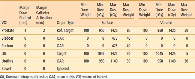
The advantage of using this type of penalty relation is that the translation from the physician expectations of the ideal dose distribution to a mathematical form is straightforward. The relation defines a clear border between acceptable and unacceptable doses and the physical meaning of dose objective is clear. Physicians have much clinical experience that can be translated into such dose objectives. In addition, this approach of defining the objectives induces an intuitive understanding of the optimization results. Moreover, this method is flexible and can describe different clinical objectives such as target minimal dose coverage and OAR protection. A set of dose objectives for HDR prostate brachytherapy is presented in the Table 13-2. In that case, dose objectives of two targets are defined—the prostate and a dominant intraprostatic lesion116—and the three OARs—the urethra, the rectum, and the bladder.
Cost Function

The weight factors are normalized using the following equation:
The constants NVOLUMES and NmzPOINTS represent the number of volumes and the number of dose points generated for the m specialty of the z volume respectively. This objective function mathematically describes the clinical objective and is used to evaluate the quality of a given dose distribution resulting from a given dwell time distribution. The closer is the dose distribution from clinical objectives; the smaller is the objective function value. The purpose of the optimization engine described in Chapter 2 is to minimize this function and find the optimal dose distribution. This function can be adapted to evaluate any type of brachytherapy plan via the definition of the global dose prescription. Therefore, it is called the adaptable objective function.
Optimization Algorithm Based on Simulated Annealing
The IPSA algorithm exploits some prior knowledge of the desired solution to constrain the solution space. This constrained solution space improves the efficiency of the random search reducing the number of iterations required by the optimization. The objective function that assigns a quantitative value to each solution is nonlinear and therefore may present multiple minima. Because the objective function cannot be simplified without loss of flexibility, the optimization approach must be able to avoid these local minima. The SA optimization engine brings the ability to overpass the local minima to continue the exploration of the solution space in an attempt to reach better solutions. Moreover, even though a local search approach may find a satisfactory clinical solution, it cannot ensure that the optimization will not result in a clinically suboptimal solution. In contrast, the application of an SA optimization engine ensures the quality of the generated treatment plan for each patient.117 In addition, the self-adaptable mechanism conceived for this algorithm clearly improves the optimization efficacy. The mechanism gradually reduced Δt during the optimization process, slowly improving the resolution. As a result, at high temperature and large Δt, the gross features of the eventual optimal solution emerge, whereas at lower temperatures and smaller Δt, finer details develop. The optimization yields a clinically optimal treatment plan in a short time. Consequently, this optimization algorithm is applicable for live treatment planning as intended.
Organ Type
Modern planning tools such as the anatomy-based IPSA,115,118 efficiently use the information from the 3-D imaging modalities at all stages of the treatment procedure. IPSA automatically and rapidly produces conformal dose coverage of the target volume while limiting the dose to OARs in the delivery of HDR brachytherapy or permanent implants. With this inverse planning approach, the focus is on the physician’s prescription and dose constraints instead of on the technical limitations. Consequently, the physician’s control of the treatment is improved. With clear anatomic images, functional images to locate the cancerous tissues, and rapid optimization to take all this information into account within the clinical time frame, plans can be generated with dose distribution that fulfill multiobjective dose constraints, sparing organs often not considered before—personalized for each patient—a task inherently difficult to achieve with forward planning.
Challenges and Opportunities
Limitation of the Task Group 43 Dose Calculation Formalism
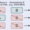
However, the data used extract the parameters assuming that there is only one seed, in a water medium, the medium having a radius of 15 cm. The final dose calculation is then performed by the simple summation of the contribution of all seeds or source positions in an implant. Taking a step back, these conditions make obvious the areas where the formalism could be less accurate: any differences in scatter condition between the data acquisition for parameter extraction and the treatment condition, the presence of any high-Z, high-density shielding materials, any significant differences (this will be defined later in this chapter) between the tissues and water, and attenuation of one source emission by another one in multiple source implants or ISA. An excellent summary can be found in Table 1 in Rivard et al.,119 which is presented by sites for low (125I range) and high (e.g., 192Ir) energy brachytherapy.
Scatter Condition
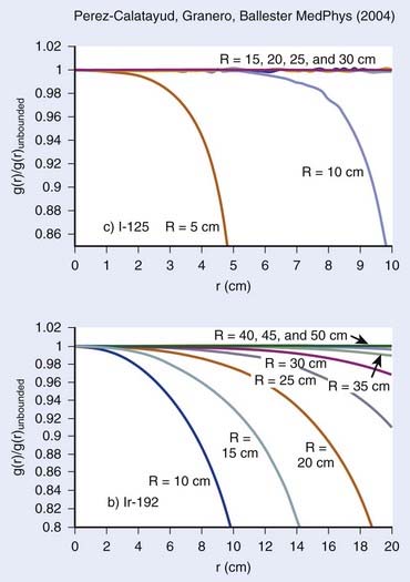
As stated previously, the condition set forth for TG43 parameter extraction is precise and requires a water equivalent medium of 15-cm radius. Furthermore, we stress that this radius condition was chosen for low-energy sources such as 125I and 103Pd. Although this condition can be easily respected in interstitial prostate implants, the geometry might differ significantly for breast implants, head and neck implants, or any other superficial implants. This particular issue has been studied extensively by Perez-Calatayud et al.,120 Melhus and Rivard,121 and Granero et al.122 For low-energy sources, the effect of a reduced radius can become important when the distance to the tissue–air junction falls below 10 cm, and can be quite significant for a distance of 5 cm or less. However, as shown in Fig. 13-2, the effect increases with photon energy. As for 192Ir, significant differences in the dose deposition can be expected within the first 10 cm of the source, even for a phantom radius of 15 cm.122 In conclusion, the effect of the difference in scatter condition increases as the photon energy increases and the distance decreases.
Shielding and Interseed Attenuation
Shielding is commonly found in brachytherapy. Usually shielded applicators are used to increase the protection to normal tissue. A number of examples can be found in gynecologic brachytherapy,123,124 for rectal HDR treatment,125 and eye plaque.126,127 In all cases, taking into account the presence of the shielding material has shown a dramatic change in dose deposition relative to the current clinical standard.
The physical explanation can be found by looking at the mass attenuation coefficients as a function of photon energy, shown in Fig. 13-3, for various materials used for shielding or that are part of the source composition. It is quite obvious that even for 192Ir brachytherapy, the effect of having high-Z materials leads to a difference in the attenuation relative to water. As expected, this effect increases as the photon energy decreases. It is due to the increasing importance of the photoelectric effect.
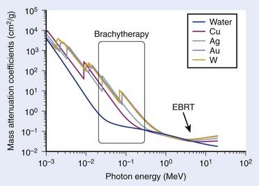
FIGURE 13-3 • Mass attenuation coefficients of water and various shielding and source composition materials as a function of energy.
(From National Institute of Standards and Technology, retrieved 16 March 2009 from www.nist.gov.)
Another important form of shielding comes from the attenuation of the radiation of one source by the presence of multiple other sources nearby. This happens particularly in PSIs in which 50 to 125 small, low-energy (20 to 30 keV) sources are used, and it is referred to in the literature as the interseed attenuation (ISA). An early study based on regular geometry configuration predicted a decrease of 6% to 10% in the minimum peripheral dose resulting from ISA.128,129 More recently, clinical seed configurations along with prostate anatomies were studied.130–132 The results indicate that a decrease of 2% to 5% of the clinical parameter D90 can be expected from ISA. This effect of the dose parameters was shown to depend on the radioisotope,130 seed density or interseed distances,131 and seed design.133
Tissue Heterogeneity
Tissue heterogeneity affects the dose calculation on two fronts. First, it affects the attenuation of the radiation as it is transported into the medium. From a physical perspective, this is characterized by the difference in the mass attenuation coefficient between water (TG43 reference medium) and the tissue of interest. Secondly, the difference in dose deposition between tissue and water is given by the mass-energy absorption coefficient, assuming electronic equilibrium. In this context, the differences for both cases depend on the energy and tissue composition (Z). Fig. 13-4 shows the mass-energy attenuation coefficient for water, adipose, breast (ICRU-44), bone, and soft tissue (ICRU-44).134 At more than 200 keV, small variations of composition from most tissues found in the human body makes little differences in the attenuation coefficients. This is because Compton scattering dominates the interaction cross-section. However, for lower photon sources such as is found in 103Pd, 125I, 131Cs, and low-energy electronic brachytherapy sources135 and even 169Yb, there are significant variations relative to water. Again, this is due to the increasing importance of the photoelectric effect.
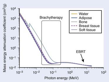
FIGURE 13-4 • Mass energy attenuation coefficients of water and various tissues as a function of energy.
(From National Institute of Standards and Technology, retrieved 16 March 2009 from www.nist.gov.)
It has been shown that for 192Ir brachytherapy, the ratio of the dose to tissue to that of water is within 1% of a ratio of 1 for the first 10 cm from the source.121 This is in strong contrast to the study of Reniers et al.,136 which looked at the term g(r) of TG43 for 103Pd seeds in various tissues. The latter study has demonstrated a strong dependence with distance, resulting in differences to water of −40% at 5 cm for breast tissue and +10% for muscle at the same distance from the source for g(r). For prostate seed implants, a retrospective postimplant Monte Carlo dose calculation study on 28 consecutive cases has shown that tissue heterogeneity accounted for a 3% decrease in D90.132 However, there were large variations from patient to patient, which, combined with ISA, resulted in a decrease of D90 from 3% to 14%. Using a lower energy isotope, 103Pd instead of 125I, decreases even further D90.130 Given the current knowledge, it should be obvious that low-energy electronic sources (lower than 100 kVp) will be affected similarly.
Potential Avenues
A few avenues are being explored to solve some of the limitations described in this section. They can be divided roughly into three categories, namely analytical algorithms, the stochastic approach or Monte Carlo, and the deterministic approach, which solve the transport equation. It is beyond the scope of this chapter to get into the details of each, and we refer the reader to recent reviews.119,137,138 However, because some of these are getting close to clinical release, a few lines should be given. The most common advance analytical methods for brachytherapy proceed by separation of the primary and scatter contribution to the dose. A well-known method is that of the collapsed–cone,139 which has been proposed for brachytherapy dose calculation.140,141 For the deterministic approach, a solution is proposed by a commercial venture, Transpire Inc. The product named Attila has been recently tested for external-beam radiotherapy,141,142 and Acuros, also by Transpire Inc., was commercialized by Varian for brachytherapy. Finally, on the Monte Carlo side, a number of codes are available to perform dose calculation within a research environment: MCNP,143,144 GEANT4145,146 EGS4,147,148 and PTRAN.149,150 However, recently new, dedicated, and extremely fast MC codes have been promoted for low-energy brachytherapy dose calculations: MCPI151 and BrachyDose.152 Thus the next few years might see a number of these different approaches used on a regular basis in our clinics.
Dose-Guided Radiation Therapy Real-Time In Vivo Dosi
Image-Guided Radiation Therapy
Possibly the most important goal of ART is to manage the real dose delivered globally to the patient and each organ of interest. Effectively, the ultimate strategy of IGRT extends beyond the geometrical verification of the patient anatomy. Dose-guided radiation therapy (DGRT) is a form of ART in which dosimetric considerations constitute the basis of treatment modification and validation. By verifying and tracking the key parameter for treatment outcomes, DGRT has great potential to improve dose distributions and treatment results. Although the concept of DGRT was first introduced in external-beam radiation therapy,152 it is more easily applied to brachytherapy. In fact, quasi real-time planning for permanent prostate implants is an attempt to perform DGRT. The concept requires performance of a postimplant dosimetry while the patient is still on the operating table, opening the possibility of modifying the dose distribution (inserting more seeds) if the dose distribution is suboptimal. This requires that seeds be visible under US imaging, technically challenging at the moment. Other possibilities include combining other imaging modalities available in the brachytherapy suite. A promising avenue is to use cone beam CT to determine the location of the seeds and US to delineate the prostate. Generally speaking, if the dose distribution can be recalculated before the patient is released, then a comparison with the intended plan can be performed and corrected if necessary.
Robotic Brachytherapy
Robots are increasingly being introduced into clinical practice. These robotic surgical assistants have the potential to provide greater precision and accuracy compared with manually controlled surgical devices, and in many cases can be used with real-time imaging. A pioneer in this area has been the commercially successful da Vinci Surgical System, a robotic surgical assistant for laparoscopic surgery developed by Intuitive Surgical that has been installed in more than 700 locations worldwide.153 In addition to the da Vinci system, numerous robotic hardware systems are being developed commercially and in academia for specialized medical procedures. Surveys of recent advances in medical robotics have been written by Taylor and Stoianovici154 and Cleary et al.155 Image-guided medical needle insertion procedures in particular can benefit from the more precise control of needle position and velocity made possible through robotic surgical assistants. One of the first medical applications of a robot was to precisely position a needle for a brain biopsy using a programmable universal machine for assembly industrial robot and a CT scanner in 1985.156 More recently, custom robotic devices have been developed to address the clinical challenges of space constraints, safety requirements, and imaging modality compatibility. Masamune et al.157 developed an easily sterilized device with detachable electrical parts for needle insertion in stereotactic neurosurgery. Fichtinger et al.158 developed a robot for transperineal needle insertion for prostate biopsy and therapy that is capable of operating inside the gantry of a CT scanner. Maurin et al.159 developed CTBot, a stereotactic-guided robotic assistant for percutaneous procedures in the abdomen. Fichtinger et al.,158 Schneider et al.,160 and Phee et al.161 developed needle-insertion robots specially designed for prostate brachytherapy with transrectal US guidance. The robot of Phee et al. achieved placement errors ranging from 2.3 mm to 6.5 mm in nine clinical biopsy cases. More recently, several groups have developed robots capable of operating in an MRI scanner, which is particularly difficult because of the limitations placed on robot materials resulting from the magnetic field required for MRI. Chinzei et al.162 and DiMaio et al.163 developed an MRI-compatible surgical assistant designed to operate in an open MRI magnet. Stoianovici et al.164 developed MrBot, a compact robotic device that uses a novel pneumatic step motor that can operate inside a closed MRI magnet. MrBot was applied to brachytherapy seed implantation in live dogs and achieved a seed placement error in the range of 1.45 to 10.54 mm, with most seeds being placed with an error of 1 to 3 mm.165 These errors are most likely the result of tissue deformations and seed migration because the robot itself achieved positioning accuracy of the needle tip in the range of 0.86 to 3.18 mm.165
Recently, dosimetric planning studies showed that inverse planning166 could be used to optimize new seed distributions, such as divergent needles for permanent implants,167 or new conical or firework catheter patterns for HDR168 in the limited space inside a closed MRI. Those new needle or catheter patterns (nonparallel) can potentially deliver equivalent dose distribution to the target while considerably reducing the physical trauma to certain organs. The experiments performed at UCSF with the 3T MRI unit successfully demonstrated that inverse-planned novel catheter patterns could be accurately delivered by the robot.
1 Thomadsen BR, Rivard MJ, Butler WM, editors. Brachytherapy physics, ed 2, Seattle: American Association of Physicists in Medicine, 2005. Medical Physics Monograph No. 31
2 Krempien RC, Dacuber S, Hensley FW, et al. Image fusion of CT and MRI data enables improved target volume definition in 3D-brachytherapy treatment planning. Brachytherapy. 2003;3:164.
3 Milicokovic N, Giannouli S, Baltas D, et al. Catheter autoreconstruction in computed tomography based brachytherapy treatment planning. Med Phys. 2000;27(5):1047.
4 Baltas D, Sakelliou L, Zamboglou N. The physics of modern brachytherapy for oncology. New York: Taylor & Francis; 2007.
5 Mayles P, Nahum AE, Rosenwald J–C. Handbook of radiotherapy physics: theory and practice. New York: Taylor & Francis; 2007.
6 Nath R, Anderson LL, Luxton G, et al. Dosimetry of interstitial brachytherapy sources: recommendation of the AAPM Radiation Therapy Committee Task Group No. 43. Med Phys. 1995;22:209.
7 Khan FM. The physics of radiation therapy, ed 4. Philadelphia: Lippincott Williams & Wilkins; 2009.
8 Rivard MJ, Coursey BM, DeWerd LA, et al. Update of AAPM Task Group No. 43 Report: a revised AAPM protocol for brachytherapy dose calculations. Med Phys. 2004;31:633.
9 Ninkovic MM, Raicevic JJ, Adrovic F. Air kerma rate constants for gamma emitters used most often in practice. Radiat Prot Dosimetry. 2005;115(1–4):247.
10 MD Anderson Cancer Center, retrieved August 2009 from http://rpc.mdanderson.org/
11 Pickett B, Pouliot J. The effect of the radial function on I-125 seeds used for permanent prostate implantation. Med Dosimetry. 2004;29(3):204.
12 Buksak D, Chow A. Preparation of carrier-free131Cs from cyclotron-irradiated cesium fluoride. J Radioanal Chem. 1973;14:197-199.
13 Prestidge BR, Bice WS, Jurkovic I, et al. Cesium-131 permanent prostate brachytherapy: an initial report. Int J Radiat Oncol Biol Phys. 2005;63(1):5336.
14 Armpilia CI, Dale RG, Coles IP, et al. The determination of radiobiologically optimized half-lives for radionuclides used in permanent brachytherapy implants. Int J Radiat Oncol Biol Phys. 2003;55(2):378.
15 Sahgal A, Jabbari S, Chen J, et al. A comparison of dosimetric and biological effective dose parameters for the prostate and urethra using Cs-131 and I-125 for prostate brachytherapy. Int J Radiat Oncol Biol Phys. 2008;72(1):247.
16 Mason DL, Battista JJ, Barnett RB, et al. Ytterbium-169: Calculated physical properties of a new radiation source for brachytherapy. Med Phys. 1992;19(3):695-703.
17 Los Alamos National Laboratory, chemistry Division, “Thulium,” retrieved August 19, 2009, from http://periodic.lanl.gov/elements/69.html
18 Granero D, Pérez-Calatayud J, Ballester F, et al. Broad-beam transmission data for new brachytherapy sources, tm-170 and yb-169. Radiat Prot Dosimetry. 2006;118(1):11.
19 Park CC, Bevan A, Podgorsak MB, et al: Electronic brachytherapy, December 3, 2007.
20 Liu D, Poon E, Bazalova M, et al. Spectroscopic characterization of a novel electronic brachytherapy system. Phys Med Biol. 2008;53(1):61.
21 Ménard C, Susil R, Choyke P, et al. MRI-guided HDR prostate brachytherapy in a standard 1.5T scanner. Int J Radiat Oncol Biol Phys. 2004;59(5):1414.
22 Pouliot J, Kim Y, Lessard E, et al. Inverse planning for HDR prostate brachytherapy use to boost dominant intra-prostatic lesion defined by magnetic-resonance spectroscopy imaging. Int J Radiat Oncol Biol Phys. 2004;59(4):1196.
23 Haie-Meder C, Pötter R, Van Limbergen E, et al. Recommendations from Gynaecological (GYN) GEC-ESTRO Working Group (I): Concepts and terms in 3D image–based 3D treatment planning in cervix cancer brachytherapy with emphasis on MRI assessment of GTV and CTV. Radiother Oncol. 2005;74(3):235.
24 Kubicky CD, Yeh B, Lessard E, et al. Inverse planning for the magnetic resonance imaging (MRI)-based intracavitary brachytherapy for cervical cancer: a feasibility study. Brachytherapy. 2008;7:242.
25 Kim Y, Hsu I-C, Lessard E, et al. Dose uncertainty due to computed tomography CT slice thickness in CT-based high dose rate brachytherapy of the prostate cancer. Med Phys. 2004;31(9):2543.
26 Yue N, Dicker AP, Nath R, et al. The impact of edema on planning 125I and 103Pd prostate implants. Med Phys. 1999;26:763.
27 Yue N, Dicker AP, Corn BW, et al. A dynamic model for the estimation of optimum timing of computed tomography scan for dose evaluation of 125I or 103Pd seed implant of prostate. Int J Radiat Oncol Biol Phys. 1999;43:447.
28 Waterman FM, Yue N, Corn BW, et al. Edema associated with I-125 or Pd-103 prostate brachytherapy and its impact on post-implant dosimetry: an analysis based on serial CT acquisition. Int J Radiat Oncol Biol Phys. 1998;41:1069.
29 Speight JL, Shinohara K, Pickett B, et al. Prostate volume change after seed implantation: Possible benefit of improved volume histogram with perioperative steroid. Int J Radiat Oncol Biol Phys. 2000;48(5):1461.
30 Prestidge BR, Bice WS, Kiefer EJ, et al. Timing of computed tomography-based postimplant assessment following permanent transperineal prostate brachytherapy. Int J Radiat Oncol Biol Phys. 1998;40:1111.
31 Roberson PL, Narayana V, McShan DL, et al. Source placement error for permanent implant of the prostate. Med Phys. 1997;24:251.
32 Butler WM, Merrick GS, Dorsey AT, et al. Isotope choice and the effect of edema on prostate brachytherapy dosimetry. Med Phys. 2000;27:1067.
33 Kim Y, Hsu I-C, Lessard E, et al. Dose uncertainty due to computed tomography CT slice thickness in CT-based high dose rate brachytherapy of the prostate cancer. Med Phys. 2004;31(9):2543.
34 Kim YB, Hsu I-C, Lessard E, et al. Prostate volume change and dosimetric impact of edema between HDR brachytherapy fractions. Int J Radiat Oncol Biol Phys. 2004;59(4):1208.
35 Kim Y, Hsu I, Pouliot J. Cranio-caudal catheter displacement between fractions in CT-based HDR brachytherapy of prostate cancer. J Appl Clin Med Phys. 2007;8(4):1.
36 Martinez AA, Pataki I, Edmundson G, et al. Phase II prospective study of the use of conformal high-dose-rate brachytherapy as monotherapy for the treatment of favorable stage prostate cancer: a feasibility report. Int J Radiat Oncol Biol Phys. 2001;49(1):61.
37 Damore SJ, Syed AM, Puthawala AA, et al. Needle displacement during HDR brachytherapy in the treatment of prostate cancer. Int J Radiat Oncol Biol Phys. 2000;46(5):1205.
38 Hoskin PJ, Bownes PJ, Ostler P, et al. High dose rate afterloading brachytherapy for prostate cancer: Catheter and gland movement between fractions. Radiother Oncol. 2003;68(3):285.
39 Mullokandov E, Gejerman G. Analysis of serial CT scans to assess template and catheter movement in prostate HDR brachytherapy. Int J Radiat Oncol Biol Phys. 2004;58(4):1063.
40 Algan O, Hanks GE, Shaer AH. Localization of the prostatic apex for radiation treatment planning. Int J Radiat Oncol Biol Phys. 1995;33:925.
41 Roach MIII, Faillace-Akazawa P, Malfatti C, et al. Prostate volumes defined by magnetic resonance imaging and computerized tomographic scans for 3-D conformal radiotherapy. Int J Radiat Oncol Biol Phys. 1996;35:1011.
42 Rasch C, Barillot I, Remeijer P, et al. Definition of the prostate in CT and MRI: a multi-observer study. Int J Radiat Oncol Biol Phys. 1999;43:57.
43 Crook J, McLean M, Yeung I, et al. MRI-CT fusion to assess postbrachytherapy prostate volume and the effects of prolonged edema on dosimetry following transperineal interstitial permanent prostate brachytherapy. Brachytherapy. 2004;3:55-60.
44 Dubois DF, Prestidge BR, Hotchkiss LA, et al. Intraobserver and interobserver variability of MR imaging– and CT-derived prostate volumes after transperineal interstitial permanent prostate brachytherapy. Radiology. 1998;207:785.
45 Smith WL, Lewis C, Bauman G, et al. Prostate volume contouring: a 3D analysis of segmentation using 3DTRUS, CT, and MR. Int J Radiat Oncol Biol Phys. 2007;67:1238.
46 Prete JJ, Prestidge BR, Bice WS, et al. Comparison of MRI- and CT-based post-implant dosimetric analysis of transperineal interstitial permanent prostate brachytherapy. Radiat Oncol Investig. 1998;6:90.
47 Polo A, Cattani F, Vavassori A, et al. MR and CT image fusion for postimplant analysis in permanent prostate seed implants. Int J Radiat Oncol Biol Phys. 2004;60:1572.
48 Stock RG, Stone NN, Tabert A, et al. A dose-response study for I-125 prostate implants. Int J Radiat Oncol Biol Phys. 1998;41:101.
49 Lee WR, Roach MIII, Michalski J, et al. Interobserver variability leads to significant differences in quantifiers of prostate implant adequacy. Int J Radiat Oncol Biol Phys. 2002;54(2):457.
50 Moerland MA, Wijrdeman HK, Beersma R, et al. Evaluation of permanent I-125 prostate implants using radiography and magnetic resonance imaging. Int J Radiat Oncol Biol Phys. 1997;37:927.
51 Dogan N, Mohideen N, Glasgow GP, et al. Effect of prostatic edema on CT-based postimplant dosimetry. Int J Radiat Oncol Biol Phys. 2002;53:483.
52 Leclerc G, Lavallee MC, Roy R, et al. Prostatic edema in 125I permanent prostate implants: dynamical dosimetry taking volume changes into account. Med Phys. 2006;33:574.
53 Badiozamani KR, Wallner K, Sutlief S, et al. Anticipating prostatic volume changes due to prostate brachytherapy. Radiat Oncol Investig. 1990;7:360.
54 Yue N, Chen Z, Peschel R, et al. Optimum timing for image-based dose evaluation of 125I and 103PD prostate seed implants. Int J Radiat Oncol Biol Phys. 1999;45:1063.
55 Villeneuve M, Leclerc G, Lessard E, et al. Relationship between isotope half-life and prostatic edema for optimal prostate dose coverage in permanent seed implants. Med Phys. 2008;35:1970.
56 Taschereau R, Roy J, Pouliot J. Monte Carlo simulations of prostate implants to improve dosimetry and compare planning methods. Med Phys. 1999;26:1952.
57 Nath S, Chen Z, Yue N, et al. Dosimetric effects of needle divergence in prostate seed implant using 125I and 103Pd radioactive seeds. Med Phys. 2000;27:1058.
58 Archambault L, Beaulieu L, Tubic D. Automatic post-implant needle reconstruction algorithm to characterize and improve implant robustness analyses. Med Phys. 2003;30:2897.
59 Beaulieu L, Archambault L, Aubin S, et al. The robustness of dose distributions to displacement and migration of 125I permanent seed implants over a wide range of seed number, activity, and designs. Int J Radiat Oncol Biol Phys. 2004;58:1298.
60 Bues M, Holupka EJ, Meskell P, et al. Effect of random seed placement error in permanent transperineal prostate seed implant. Radiother Oncol. 2006;79:70.
61 Butler WM, Merrick GS, Lief JH, et al. Comparison of seed loading approaches in prostate brachytherapy. Med Phys. 2000;27:381.
62 Steinfeld AD, Donahue BR, Plaine L. Pulmonary embolization of iodine-125 seeds following prostate implantation. Urology. 1991;37:149.
63 Zhu AX, Wallner KE, Frivold GP, et al. Prostate brachytherapy seed migration to the right coronary artery associated with an acute myocardial infarction. Brachytherapy. 2006;5:262.
64 Miura N, Kusuhara Y, Numata K, et al. Radiation pneumonitis caused by a migrated brachytherapy seed lodged in the lung. Jpn J Clin Oncol. 2008;38:623.
65 Nguyen BD, Schild SE, Wong WW, et al. Prostate brachytherapy seed embolization to the right renal artery. Brachytherapy. 2009;8:309-312.
66 Nag S, Vivekanandam S, Martinez-Monge R. Pulmonary embolization of permanently implanted radioactive palladium-103 seeds for carcinoma of the prostate. Int J Radiat Oncol Biol Phys. 1997;39:667.
67 Cosset JM, Pinillos-Ashton L, Mettler F. [The recommendations of the International Commission on Radiological Protection (ICRP) for high-dose-rate brachytherapy and for permanent prostatic implants.]. Cancer Radiother. 2004;8(Suppl 1):S50.
68 Chen QS, Blair HF. Accurate and efficient detection of pulmonary seed embolization in prostate iodine-125 permanent brachytherapy with a collimated gamma scintillation survey meter. Med Phys. 2003;30:785.
68a Morrier J, Chrétien M, Martin AG, et al: A more efficient, radiation-free alternative to systematic chest x-ray for the detection of embolized seeds to the lung, Int J Radiat Oncol Biol Phys (2010). In press.
69 Ding M, Wei Z, Gardi L, et al. Needle and seed segmentation in intra-operative 3D ultrasound-guided prostate brachytherapy. Ultrasonics. 2006;44(Suppl 1):e331.
70 Tubic D, Zaccarin A, Pouliot J, et al. Automated seed detection and three-dimensional reconstruction. I. Seed localization from fluoroscopic images or radiographs. Med Phys. 2001;28:2265.
71 Tubic D, Zaccarin A, Beaulieu L, et al. Automated seed detection and three-dimensional reconstruction. II. Reconstruction of permanent prostate implants using simulated annealing. Med Phys. 2001;28:2272.
72 Todor DA, Cohen GN, Amols HI, et al. Operator-free, film-based 3D seed reconstruction in brachytherapy. Phys Med Biol. 2002;47:2031.
73 Narayanan S, Cho PS, Marks RJ. Fast cross-projection algorithm for reconstruction of seeds in prostate brachytherapy. Med Phys. 2002;29:1572.
74 Tutar IB, Managuli R, Shamdasani V, et al. Tomosynthesis-based localization of radioactive seeds in prostate brachytherapy. Med Phys. 2003;30:3135.
75 Westendorp H, Hoekstra CJ, Van’t Riet A, et al. Intraoperative adaptive brachytherapy of iodine-125 prostate implants guided by C-arm cone-beam computed tomography-based dosimetry. Brachytherapy. 2007;6:231.
76 Holupka EJ, Meskell PM, Burdette EC, et al. An automatic seed finder for brachytherapy CT postplans based on the Hough transform. Med Phys. 2004;31:2672.
77 Tubic D, Beaulieu L. Sliding slice: A novel approach for high accuracy and automatic 3D localization of seeds from CT scans. Med Phys. 2005;32:163.
78 De Brabandere M, Kirisits C, Peeters R, et al. Accuracy of seed reconstruction in prostate postplanning studied with a CT- and MRI-compatible phantom. Radiother Oncol. 2006;79:190.
79 Lindsay PE, Van Dyk J, Battista JJ. A systematic study of imaging uncertainties and their impact on 125I prostate brachytherapy dose evaluation. Med Phys. 2003;30:1897.
80 Su Y, Davis BJ, Furutani KM, et al. Dosimetry accuracy as a function of seed localization uncertainty in permanent prostate brachytherapy: increased seed number correlates with less variability in prostate dosimetry. Phys Med Biol. 2007;52:3105.
81 Bloch BN, Lenkinski RE, Helbich TH, et al. Prostate postbrachytherapy seed distribution: Comparison of high-resolution, contrast-enhanced, T1- and T2-weighted endorectal magnetic resonance imaging versus computed tomography: initial experience. Int J Radiat Oncol Biol Phys. 2007;69:70.
82 Su Y, Davis BJ, Herman MG, et al. Examination of dosimetry accuracy as a function of seed detection rate in permanent prostate brachytherapy. Med Phys. 2005;32:3049.
83 Miquel ME, Rhode KS, Acher PL, et al. Using combined x-ray and MR imaging for prostate I-125 post-implant dosimetry: phantom validation and preliminary patient work. Phys Med Biol. 2006;51:1129.
84 Beaulieu L, Verhaegen F. Prostate postbrachytherapy seed distribution: comparison of high-resolution, contrast-enhanced, T1- and T2-weighted endorectal magnetic resonance imaging versus computed tomography: initial experience: In regard to BLOCH, et al. Int J Radiat Oncol Biol Phys. 2008;71:1289.
85 Pouliot J, Tremblay D, Roy J, et al. Optimization of permanent 125I prostate implants using fast simulated annealing. Int J Radiat Oncol Biol Phys. 1996;36(3):711.
86 Taschereau R, Roy J, Pouliot J. Monte Carlo simulation of prostate implants to improve dosimetry and compare planning methods. Med Phys. 1999;26(9):1952.
87 Narayana V, Troyer S, Evans V, et al. Randomized trial of high- and low-source strength 1251 prostate seed implants. Int J Radiat Oncol Biol Phys. 2005;61:44.
88 Sloboda R, Pedersen JE, Halperin E. Is there a preferred strength for regularly spaced 125I seeds in inverse-planned prostate implants. Int J Radiat Oncol Biol Phys. 2003;55:234.
89 Sloboda RS, Pedersen JE, Hanson J, et al. Dosimetric consequences of increased seed strength for I-125 prostate implants. Radiother Oncol. 2003;68:295.
90 Nag S, Bice W, DeWyngaert K, et al. The American Brachytherapy Society recommendations for permanent prostate brachytherapy postimplant dosimetric analysis. Int J Radiat Oncol Biol Phys. 2000;46(1):221.
91 Kim Y, Hsu I, Lessard E, et al. Class solution in inverse planned HDR prostate brachytherapy for dose escalation of DIL defined by combined MRI/MRSI. Radiother Oncol. 2008;88(1):148.
92 Sahgal A, Roach III M. Permanent prostate seed brachytherapy: a current perspective on the evolution of the technique and its application. Nat Clin Pract Oncol. 2007;4(12):658.
93 Hsu IC, Shinohara K, Pouliot J, et al. RTOG-0321 protocol: phase II trial of combined high dose rate brachytherapy and external-beam radiotherapy for adenocarcinoma of the prostate. http://www.rtog.org.
94 Nag S, Cardenes H, Chang S, et al. Proposed guidelines for image-based intracavitary brachytherapy for cervical carcinoma: report from Image-Guided Brachytherapy Working Group. Int J Radiat Oncol Biol Phys. 2004;60(4):1160.
95 Milickovic N, Lahanas M, Papagiannopoulou M, et al. Multiobjective anatomy-based dose optimization for HDR-brachytherapy with constraint free deterministic algorithms. Phys Med Biol. 2002;47:2263.
96 Gabor J, Streeter OE, Astrahan MA. The use of linear programming in optimization of HDR implant dose distributions. Med Phys. 2003;30(5):751.
97 Roy JN, Wallner K, Chiu-Tsao S, et al. CT based optimization planning for transperineal prostate implant with customized template. Int J Radiat Oncol Biol Phys. 1991;21:483.
98 Chen Y, Boyer AL, Xing L. A dose-volume histogram based optimization algorithm for ultrasound guided prostate implants. Med Phys. 2000;27:2286.
99 Lahanas M, Baltas D, Zamboglou N. Anatomy-based three dimensional dose optimization in brachytherapy using multiobjective genetic algorithms. Med Phys. 1999;26(9):1904.
100 Yu Y, Zhang JB, Cheng G, et al. Multi-objective optimization in radiotherapy: application to stereotactic radiosurgery and prostate brachytherapy. Artif Intell Med. 2000;19:39.
101 Lahanas M, Baltas D, Zamboglou N. A hybrid evolutionary algorithm for multi-objective anatomy-based dose optimization in high dose rate brachytherapy. Med Phys Biol. 2003;48:399.
102 Yu Y, Schell MC. Genetic algorithm for optimization of prostate implants. Med Phys. 1996;23:2085.
103 Yang G, Reinstein LE, Pai S, et al. A new genetic algorithm technique in optimization of permanent 125I prostate implants. Med Phys. 1998;25(12):2308.
104 Yamada Y, Potters L, Zaider M, et al. Impact of intraoperative edema during transperineal permanent prostate brachytherapy on computer-optimized and preimplant planning techniques. Am J Clin Oncol. 2003;26(5):e130-135.
105 De Jung KA. Genetic algorithms are NOT function optimizers. In: Whitley D, editor. Foundations of genetic algorithm: proceeding 24–29 July 1992. Vail, Colo: Morgan Kaufman, 1992.
106 Forrest S. Genetic algorithms: principles of natural selection applied to computation. Science. 1993;261(5123):872.
107 Ingber L. Adaptive simulated annealing (ASA): lessons learned. J Control Cybernetics. 1996;25(1):33.
108 Geman S, Geman D. Stochastic relation, Gibbs distribution and Bayesian restoration images. IEEE Trans Patt Anal Mach Intell. 1984;6(6):721.
109 Van Laarshoven PJM, Aarts EHL. Simulated annealing: theory and applications. Boston: D. Reidel; 1987.
110 Aart E, Korst J. Simulated annealing and Boltzmann machine. New York: John Wiley & Sons; 1989.
111 Alterovitz R, Goldberg K, Pouliot J, et al. Registration of MR prostate images with biomechanical modeling and nonlinear parameter estimation. Med Phys. 2006;33(2):446.
112 Sloboda RS. Optimization of brachytherapy dose distribution by simulated annealing. Med Phys. 1993;19:955.
113 Pouliot J, Taschereau R, Coté C, et al. Dosimetric aspects of permanents radioactive implants for the treatment of prostate. Can J Phys. 1999;55(2):61.
114 Redpath AT. Automatic determination of needle and source positions for brachytherapy of the prostate using 125 iodine rapid strand. Radiother Oncol. 2002;65:215.
115 Lessard E, Pouliot J. Inverse planning anatomy-based dose optimization for HDR-brachytherapy of the prostate using fast simulated annealing algorithm and dedicated objective function. Med Phys. 2001;28(5):773.
116 Pickett B, Verhey L, Roach III M. Fixed field intensity modulation to treat a dominant intra-prostatic lobe (DIL) to >90 Gy compared to seven field 3-dimensional non-coplanar radiotherapy. Int J Radiat Oncol Biol Phys. 1997;39(2, Suppl):41.
117 Alterovitz R, Lessard E, Pouliot J, et al. Optimization of HDR brachytherapy dose distributions using linear programming with penalty costs. Med Phys. 2006;33(11):4012.
118 Pouliot J, Lessard E, Hsu IC. Advanced 3D planning in brachytherapy. In Thomadsen BR, Rivard MJ, Butler WM, editors: Brachytherapy physics, ed 2, Seattle: American Association of Physicists in Medicine, 2005. Medical Physics Monograph No. 31
119 Rivard MJ, Venselaar JLM, Beaulieu L. The evolution of brachytherapy treatment planning. Med Phys. 2009;36:2136.
120 Perez-Calatayud J, Granero D, Ballester F. Phantom size in brachytherapy source dosimetric studies. Med Phys. 2004;31:2075.
121 Melhus CS, Rivard MJ. Approaches to calculating AAPM TG-43 brachytherapy dosimetry parameters for Cs, I, Ir, Pd, and Yb sources. Med Phys. 2006;33:1729.
122 Granero D, Perez-Calatayud J, Pujades-Claumarchirant MC, et al. Equivalent phantom sizes and shapes for brachytherapy dosimetric studies of Ir and Cs. Med Phys. 2008;35:4872.
123 Markman J, Williamson JF, Dempsey JF, et al. On the validity of the superposition principle in dose calculations for intracavitary implants with shielded vaginal colpostats. Med Phys. 2001;28:147.
124 Sureka CS, Aruna P, Ganesan S, et al. Computation of relative dose distribution and effective transmission around a shielded vaginal cylinder with 192Ir HDR source using MCNP4B. Med Phys. 2006;33:1552.
125 Poon E, Williamson JF, Vuong T, et al. Patient-specific Monte Carlo dose calculations for high-dose-rate endorectal brachytherapy with shielded intracavitary applicator. Int J Radiat Oncol Biol Phys. 2008;72:1259.
126 Melhus CS, Rivard MJ. COMS eye plaque brachytherapy dosimetry simulations for 103Pd, 125I, and 131Cs. Med Phys. 2008;35:3364.
127 Thomson RM, Taylor REP, Rogers DWO. Monte Carlo dosimetry for 125I and 103Pd eye plaque brachytherapy. Med Phys. 2008;35:5530.
128 Meigooni AS, Meli JA, Nath R. Interseed effects on dose for 125I brachytherapy implants. Med Phys. 1992;19:385.
129 Mobit P, Badragan I. Dose perturbation effects in prostate seed implant brachytherapy with I-125. Phys Med Biol. 2004;49:3171.
130 Chibani O, Williamson JF, Todor D. Dosimetric effects of seed anisotropy and interseed attenuation for 103Pd and 125I prostate implants. Med Phys. 2005;32:2557.
131 Carrier JF, Beaulieu L, Therriault-Proulx F, et al. Impact of interseed attenuation and tissue composition for permanent prostate implants. Med Phys. 2006;33:595.
132 Carrier JF, D’Amours M, Verhaegen F, et al. Postimplant dosimetry using a Monte Carlo dose calculation engine: a new clinical standard. Int J Radiat Oncol Biol Phys. 2007;68:1190.
133 Afsharpour H, D’Amours M, Cote B, et al. A Monte Carlo study on the effect of seed design on the interseed attenuation in permanent prostate implants. Med Phys. 2008;35:3671.
134 International Commission on Radiation Units and Measurements. Tissue substitutes in radiation dosimetry and measurement ICRU report 44. International Commission on Radiation Units and Measurements; 1989.
135 Reniers B, Liu D, Rusch T, et al. Calculation of relative biological effectiveness of a low-energy electronic brachytherapy source. Phys Med Biol. 2008;53:7125.
136 Reniers B, Verhaegen F, Vynckier S. The radial dose function of low-energy brachytherapy seeds in different solid phantoms: comparison between calculations with the EGSnrc and MCNP4C Monte Carlo codes and measurements. Phys Med Biol. 2004;49:1569.
137 Ahnesjo A, Aspradakis MM. Dose calculations for external photon beams in radiotherapy. Phys Med Biol. 1999;44:R99.
138 Rogers DWO. Fifty years of Monte Carlo simulations for medical physics. Phys Med Biol. 2006;51:R287.
139 Ahnesjo A. Collapsed cone convolution of radiant energy for photon dose calculation in heterogeneous media. Med Phys. 1989;16:577.
140 Carlsson AK, Ahnesjo A. The collapsed cone superposition algorithm applied to scatter dose calculations in brachytherapy. Med Phys. 2000;27:2320.
141 Carlsson Tedgren A, Ahnesjo A. Optimization of the computational efficiency of a 3D, collapsed cone dose calculation algorithm for brachytherapy. Med Phys. 2008;35:1611.
142 Gifford KA, Horton JL, Wareing TA, et al. Comparison of a finite-element multigroup discrete-ordinates code with Monte Carlo for radiotherapy calculations. Phys Med Biol. 2006;51:2253.
143 Forster RA, Godfrey TNK: United States, 1985 (unpublished).
144 Waters LS, McKinney GW, Durkee JW, et al: The MCNPX Monte Carlo radiation transport code. AIP Conference Proceedings: Hadronic shower simulation workshop, Batavia, Ill, 6–8 Sep 2006 2007;896:81–90.
145 Agostinelli S, Allison J, Amako K, et al. G4—A simulation toolkit. Nucl Instrum Methods Phys Res A. 2003;506:250.
146 Allison J, Amako K, Apostolakis J, et al. Geant4 developments and applications. IEEE Trans Nucl Sci. 2006;53:270.
147 Nelson WR, Hirayama H, Rogers DWO, Report No. SLAC-265; 1985.
148 Kawrakow I, Rogers DWO, Report No. Report PIRS-701; 2006.
149 Williamson JF. Monte Carlo evaluation of kerma at a point for photon transport problems. Med Phys. 1987;14:567.
150 Li Z, Williamson JF. Volume-based geometric modeling for radiation transport calculations. Med Phys. 1992;19:667.
151 Chibani O, Williamson JF. MCPI: A sub-minute Monte Carlo dose calculation engine for prostate implants. Med Phys. 2005;32:3688.
152 Taylor RE, Yegin G, Rogers DW. Benchmarking brachydose: voxel based EGSnrc Monte Carlo calculations of TG-43 dosimetry parameters. Med Phys. 2007;34:445.
153 Intuitive Surgical, Inc Retrieved 03 January 2009 from http://www.intuitivesurgical.com
154 Taylor RH, Stoianovici D. Medical robotics in computer-integrated surgery. IEEE Trans Rob Autom. 2003;19(5):765. 781
155 Cleary K, Melzer A, Watson V, et al. Interventional robotic systems: applications and technology state-of-the-art. Minim Invasiv Ther Allied Technol. 2006;15(2):101. 113
156 Kwoh YS, Hou J, Jonckheere EA, et al. A robot with improved absolute positioning accuracy for CT guided stereotactic brain surgery. IEEE Trans Biomed Eng. 1988;35(2):153.
157 Masamune K, Ji LH, Suzuki M, et al, A newly developed stereotactic robot with detachable drive for neurosurgery; Medical Image Computing and Computer Assisted Intervention (MICCAI); 1998:215.
158 Fichtinger G, Burdette EC, Tanacs A, et al. Robotically assisted prostate brachytherapy with transrectal ultrasound guidance phantom experiments. Brachytherapy. 2006;5(1):14.
159 Maurin B, Doignon C, Ganglo J, et al. CT-Bot: a stereotactic-guided robotic assistant for percutaneous procedures of the abdomen. Proc SPIE Med Imag. 2005:241.
160 Schneider C, Okamura AM, Fichtinger G. A robotic system for transrectal needle insertion into the prostate with integrated ultrasound. Proc IEEE Int Conf Rob Autom. 2004:2085.
161 Phee L, Xiao D, Yuen J, et al. Ultrasound guided robotic system for transperineal biopsy of the prostate. Proc IEEE Int Conf Rob Autom. 2005:1327.
162 Chinzei K, Hata N, Jolesz FA, et al. MR compatible surgical assist robot: system integration and preliminary feasibility study. In: Medical Image Computing and Computer Assisted Intervention (MICCAI). New York: Springer; 2000:921.
163 DiMaio SP, Pieper S, Chinzei K, et al. Robot-assisted needle placement in open-MRI: system architecture, integration and validation. In: Westwood JD, et al, editors. Medicine meets virtual reality 14. Washington, DC: IOS Press; 2006:126.
164 Stoianovici D, Song D, Petrisor D, et al. MRI “stealth” robot for prostate interventions. Minim Invasive Ther Allied Technol. 2007;16(4):241.
165 Muntener M, Patriciu A, Petrisor D, et al. Transperineal prostate intervention: Robot for fully automated MR imaging—system description and proof of principle in a canine model. Radiology. 2008;247(2):543.
166 Lessard E, Kwa SLS, Pickett B, et al. Class solution for inversely planned permanent prostate implants to mimic an experienced dosimetrist for pre and real-time treatment planning. Med Phys. 2006;33(8):2773.
167 Marion PR, Van Gellekom MP, Marinus A, et al. MRI-guided prostate brachytherapy with single needle method—a planning study. Radiother Oncol. 2004;71:327.
168 Cunha Hsu IC, Pouliot J, Roach III M, et al: Toward adaptive stereotactic robotic brachytherapy for prostate cancer: giving a robot a brain, Sci Med Appl, in press.